

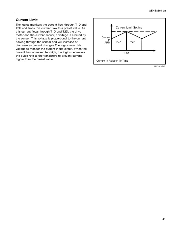
Mitsubishi 2FBC18 Forklift Service Manual
$50.00
- Type Of Manual: Service Manual
- Number of Pages: 623
- Size: 6.8MB
- Format: PDF
Product details
-
Model List:
- 2FBC18 Forklift
- 1. GENERAL INFORMATION
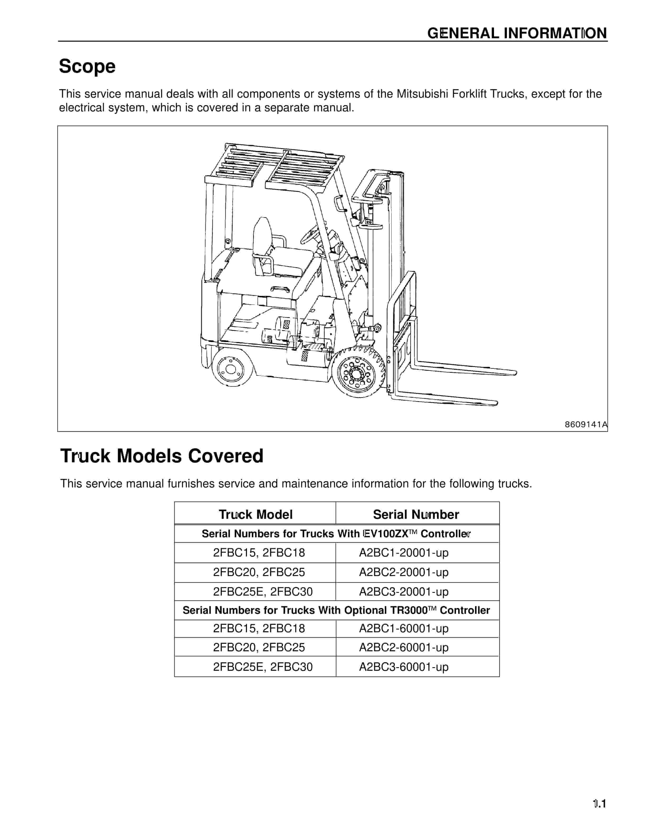
- 1.1. Truck Models Covered
- 1.2. Nameplate and Serial Number Locations
- 1.3. Dimensions
- 1.3.1. Dimensions Chart
- 1.4. General Information (Standard Models)
- 2. BRAKE SYSTEM DESCRIPTION
- 2.1. Description
- 2.1.1. Automatic Adjusting Device
- 2.1.2. General Information
- 2.2. Master Cylinder
- 2.2.1. Disassembly
- 2.2.2. Inspection after Disassembly
- 2.2.3. Reassembly
- 2.3. Service Brakes
- 2.3.1. Disassembly
- 2.3.2. Inspection after Disassembly
- 2.3.3. Reassembly
- 2.4. Wheel Cylinders
- 2.4.1. Disassembly
- 2.4.2. Inspection after Disassembly
- 2.4.3. Reassembly
- 2.4.4. Inspection and Adjustment
- 3. Front Axle
- 3.1. Front Axle
- 3.1.1. Description
- 3.1.2. Front Wheels
- 3.1.3. Installation
- 3.1.4. Disassembly
- 3.1.5. Inspection after Disassembly
- 3.1.6. Reassembly
- 3.2. Reduction Differential
- 3.2.1. Description
- 3.2.2. Disassembly
- 3.2.3. Inspection after Disassembly
- 3.2.4. Reassembly
- 3.2.5. Inspection and Adjustment
- 4. Hydraulic System
- 4.1. Hydraulic System
- 4.1.1. Description
- 4.1.2. Removal and Installation Warning
- 4.2. Hydraulic Pump
- 4.2.1. Removal
- 4.2.2. Installation
- 4.2.3. Disassembly
- 4.2.4. Inspection after Disassembly
- 4.2.5. Reassembly
- 4.2.6. Inspection after Reassembly
- 4.3. Priority Valve
- 4.3.1. Disassembly
- 4.3.2. Reassembly
- 4.4. Control Valve
- 4.4.1. Removal
- 4.4.2. Installation
- 4.4.3. Disassembly
- 4.4.4. Inspection after Disassembly
- 4.4.5. Reassembly
- 4.5. Lift and Tilt Cylinders
- 4.5.1. Removal
- 4.5.2. Disassembly
- 4.5.3. Precautions for Reassembly
- 4.5.4. Flow Regulator Valve
- 4.6. Inspection and Adjustment
- 4.6.1. Hydraulic Tank
- 4.6.2. Control Valve
- 4.6.3. Lift and Tilt Cylinders
- 5. Maintenance Service Data Drive Unit
- 5.1. Maintenance Service Data
- 5.1.1. Front Axle and Reduction Differential
- 5.1.2. Transfer Case
- 5.1.3. Rear Axle
- 5.1.4. Brake System
- 5.1.5. Steering System
- 5.1.6. Hydraulic System
- 5.1.7. Mast and Forks (Simplex Mast)
- 5.2. Tightening Torques for Standard Bolts and Nuts
- 5.2.1. Fine Thread – With Spring Washer
- 5.2.2. Fine Thread – Without Spring Washer
- 5.2.3. Coarse Thread – With Spring Washer
- 5.2.4. Coarse Thread – Without Spring Washer
- 5.3. Maintenance Chart
- 5.4. Periodic Replacement Parts
- 5.5. Lubrication Information
- 5.5.1. Lubrication Chart
- 5.5.2. Fuel and Lubricant Specifications
- 5.5.3. Recommended Brands of Lubricants
- 5.6. Weight of Major Components (Approximate)
- 5.7. Special Service Tools
- 5.7.1. Special Tool Illustrations
- 5.8. Inspection Guide
- 6. MAST AND FORKS EARLIER VERSION DESCRIPTION
- 6.1. Description
- 6.1.1. Components
- 6.1.2. Mast and Forks
- 6.1.3. Mast and Lift Bracket Assembly
- 6.2. Removal Installation
- 6.3. Disassembly
- 6.4. Inspection after Disassembly
- 6.5. Reassembly
- 6.6. Inspection and Adjustment
- 6.6.1. Chain Tension Adjustment
- 6.6.2. Clearance Adjustment on Lift Bracket
- 6.6.3. Mast Clearance Adjustment
- 6.6.4. Main Roller Shim Replacement
- 6.6.5. Mast Adjustment Chart
- 7. Mast and Forks Later Version
- 7.1. Description
- 7.2. Removal and Installation
- 7.3. Disassembly
- 7.4. Reassembly
- 7.5. Inspection and Adjustment
- 7.5.1. Chain Tension Adjustment
- 7.5.2. Clearance Adjustment on Lift Bracket
- 7.5.3. Mast Clearance Adjustment
- 7.5.4. Main Roller Shim Replacement
- 7.5.5. Mast Strip Adjustment
- 7.5.6. Tilt Angle Adjustment
- 7.5.7. Lift Cylinder Stroke Adjustment
- 7.5.8. Bleeding Lift Cylinders
- 7.6. Service Data
- 7.7. Troubleshooting
- 8. Rear Axle
- 8.1. Description
- 8.2. Rear Wheels
- 8.2.1. Removal
- 8.2.2. Installation
- 8.3. Rear Axle
- 8.3.1. Removal
- 8.3.2. Installation
- 8.3.3. Disassembly
- 8.3.4. Inspection after Disassembly
- 8.3.5. Reassembly
- 8.4. Inspection and Adjustment
- 8.4.1. Minimum Turning Radius Adjustment
- 9. Steering System
- 9.1. Steering System
- 9.1.1. Description
- 9.2. Steering Gear
- 9.2.1. Removal
- 9.2.2. Installation
- 9.2.3. Disassembly
- 9.2.4. Reassembly
- 9.3. Steer Pump
- 9.3.1. Removal
- 9.3.2. Installation
- 9.3.3. Disassembly
- 9.3.4. Reassembly
- 10. Transfer Case Earlier Version
- 10.1. Description
- 10.1.1. Earlier Version
- 10.1.2. Later Version
- 10.2. Disassembly
- 10.2.1. Removal Sequence
- 10.3. Reassembly
- 11. Troubleshooting Front Axle and Reduction Differential
- 11.1. Front Axle and Reduction Differential
- 11.2. Brake System
- 11.3. Steering System
- 11.4. Hydraulic System
- 11.5. Rear Axle
- 11.6. Mast and Forks
- 12. CHECKS REPAIRS
- 12.1. CHECKS REPAIRS
- 12.1.1. General Information
- 12.1.2. Electric Truck Motors and Controls
- 12.1.3. Unsatisfactory Brush Performance
- 12.1.4. Commutator Surfaces
- 12.1.5. Motor Winding Specifications
- 13. Electrical Testing
- 13.1. ELECTRICAL TESTING
- 13.1.1. Testing Transistors
- 13.1.2. Electrical System Adjustments
- 14. EV100ZX DIAGNOSTIC STATUS CODES
- 14.1. DIAGNOSTIC STATUS CODES
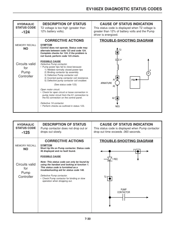
- 14.1.1. Basic Checks
- 14.1.2. On Board Diagnostics
- 14.1.3. Status Codes
- 15. EV100ZX SCR Motor Controller
- 15.1. GENERAL INFORMATION FEATURES
- 15.1.1. Safety Precautions
- 15.1.2. Glossary
- 15.1.3. Nameplate and Serial Number Locations
- 15.1.4. EV100ZX Motor Controller without SCR Hydraulics
- 15.1.5. EV100ZX Motor Controller with Optional SCR Hydraulics
- 15.1.6. Basics of Circuit Operation
- 15.1.7. Traction Control Logic Flow Chart
- 15.1.8. Console (Display)
- 15.1.9. Features of the EV100ZX Control Systems
- 15.1.10. General Maintenance for the EV100ZX Motor Controller
- 15.1.11. Trouble-shooting the EV100ZX Motor Controller
- 15.1.12. EV100ZX SCR Control Wiring Schematic without SCR Hydraulics
- 15.1.13. EV100ZX SCR Control Wiring Schematic with SCR Hydraulics
- 15.1.14. EV100ZX SCR Control Wiring Schematic for Optional Equipment
- 16. HANDSET
- 16.1. HANDSET
- 16.1.1. General Information
- 16.1.2. Function Numbers (Traction)
- 16.1.3. Function Set-Up Procedures for Optional SCR Hydraulics
- 17. LOGIC CARD CONNECTIONS TROUBLESHOOTING BY SYMPTOM
- 17.1. LOGIC CARD CONNECTIONS TROUBLESHOOTING BY SYMPTOM
- 17.1.1. Main Logic Card
- 17.1.2. Component Locations
- 17.1.3. Terminal Connections for ZX Logic Cards
- 17.1.4. EV100ZX Logic Card Specifications
- 17.1.5. EV100ZX Current Limit Curves
- 17.1.6. Secondary Troubleshooting
- 17.1.7. Hydraulic Pump Control Troubleshooting
- 18. Power Cable Connections
- 18.1. Power Cable Connections
- 18.2. Standard Control
- 18.3. Optional SCR Hydraulic Control
- 18.4. Traction Control Card Wire Harness Connections
- 18.5. A B Plugs
- 18.6. Truck Management Module 1
- 18.7. TB Connections
- 18.8. Control Card Wire Harness Connections for Optional Hydraulic Pump SCR
- 18.9. Panel Connector
- 18.10. TB Connections
- 18.11. A B Plugs
- 18.12. Y Plug for use on Option Card
- 18.13. Z Plug for use on Option Card
- 18.14. Pump Driver
- 18.15. Pump Time Delay
- 19. THEORY OF OPERATION
- 19.1. THEORY OF OPERATION
- 19.1.1. Electronic Speed Controls
- 19.1.2. Flyback Current from the Motor
- 19.1.3. Control Cards
- 19.1.4. Sequence of Operation
- 19.1.5. SCR Control (Hydraulic Pump Motor)
- 19.1.6. Contactors
- 19.1.7. Circuit Protection
- 19.1.8. Truck Mangement Module (TMM1)
- 19.1.9. Instrument Panel Display
- 19.1.10. Power Cable Connections
- 19.1.11. Traction Control Card Wire Harness Connections
- 19.1.12. Control Card Wire Harness Connections for Optional Hydraulic Pump SCR
- 19.1.13. Pump Driver
- 19.1.14. Pump Time Delay
- 20. Circuit Testing
- 20.1. CIRCUIT TESTS
- 21. Component Testing
- 21.1. ELECTRICAL TESTING
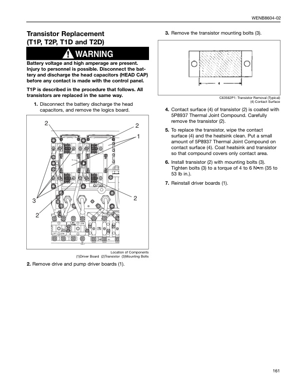
- 21.1.1. Testing Transistors
- 21.1.2. Electrical System Adjustments
- 22. Hydraulics
- 22.1. HYDRAULICS
- 22.1.1. Actuation Circuit
- 22.1.2. Capacitor Charging Circuit
- 22.1.3. Hydraulic Pump Motor Circuit
- 22.1.4. Lift Circuit
- 23. System Operating and test equipment
- 23.1. SYSTEMS OPERATION AND TEST EQUIPMENT
- 23.1.1. Conductor And Switch Continuity Tests
- 23.1.2. Contactor
- 23.1.3. Driver Board Tests
- 23.1.4. Traction Motor Current Sensor Test
- 24. System Operation
- 24.1. SYSTEMS OPERATION
- 24.1.1. Glossary
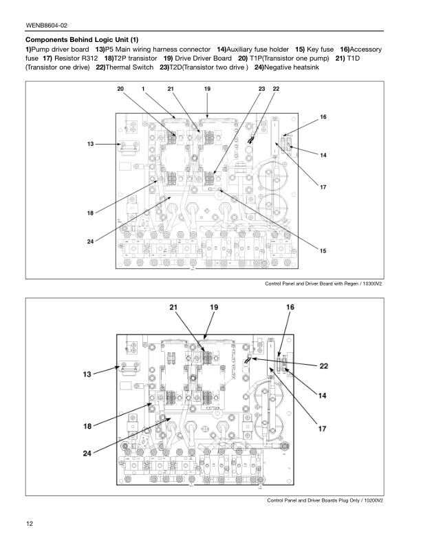
- 24.1.2. Location of Control Panel Components
- 24.1.3. Symbol Library
- 24.1.4. General Information
- 24.1.5. Programmable Setup Options
- 24.1.6. Accessing Programmable Setup Options
- 24.1.7. Operational Circuit Elements
- 24.1.8. Run-Time Diagnostics
- 24.1.9. Chat Mode
- 24.1.10. Contactors
- 24.1.11. Accelerator Control
- 24.1.12. Circuits
- 24.1.13. Drive Circuit
- 24.1.14. Power Transistors
- 25. Systems Operation
- 25.1. SYSTEMS OPERATION
- 25.1.1. Glossary
- 25.1.2. Location of Control Panel Components
- 25.1.3. Symbol Library
- 25.1.4. General Information
- 25.1.5. Programmable Setup Options
- 25.1.6. Accessing Programmable Setup Options
- 25.1.7. Operational Circuit Elements
- 25.1.8. Run-Time Diagnostics
- 25.1.9. Chat Mode
- 25.1.10. Contactors
- 25.1.11. Accelerator Control
- 25.1.12. Circuits
- 25.1.13. Drive Circuit
- 25.1.14. Power Transistors
- 26. Testing-Adjusting
- 26.1. TESTING AND ADJUSTING
- 26.1.1. Accessing Stored Fault Codes
- 27. TR3000 CONTROL
- 27.1. GENERAL INFORMATION
- 27.1.1. Mitsubishi Forklift Truck Important Safety Information
- 27.1.2. Specifications
- 28. Trouble Shooting
- 28.1. TROUBLESHOOTING
- 28.1.1. Troubleshooting Checklist
- 28.1.2. Control And Power System Operational Checks
- 29. Troubleshooing Chart
- 29.1. TROUBLESHOOTING CHARTS
Related products
-
Mitsubishi 4G33, 4G52, 4G54 Service Manual 99719-42120
$50.00 Add to cart -
Mitsubishi 4DQ5, S4E, S6E, S6E2 Service Manual 99719-52120
$50.00 Add to cart -
Mitsubishi 1204E Diesel Engine Troubleshooting Service Manual 99799-56104
$50.00 Add to cart -
Mitsubishi 4DQ5, S4E, S4E2 Service Manual 99719-52130
$50.00 Add to cart -
Mitsubishi 4G63, 4G64 Fuel System Supplement Service Manual 99729-75110
$50.00 Add to cart


