


Mitsubishi FB16K, FB18K, FB20KC Chassis, Mast and Options Service Manual 99759-52100
$50.00
- Type Of Manual: Service Manual
- Manual ID: 99759-52100
- Number of Pages: 492
- Size: 7.7MB
- Format: PDF
Product details
-
Model List:
- FB16K, FB18K, FB20KC
- 1. General
- 1.1. GENERAL INFORMATION
- 1.1.1. Foreword
- 1.1.2. How To Read This Manual
- 1.1.3. Vehicle Exterior
- 1.1.4. Serial Number Locations
- 1.1.5. Chassis and Mast Model Identification
- 1.1.6. Dimensions
- 1.1.7. Technical Data
- 2. BRAKE SYSTEM
- 2.1. BRAKE SYSTEM
- 2.1.1. Specifications
- 2.1.2. Structure and Functions
- 2.1.3. Procedures and Key Points for Disassembly and Reassembly
- 2.1.4. Inspection and Adjustment
- 2.1.5. Troubleshooting
- 2.1.6. Service Data
- 3. HYDRAULIC SYSTEM
- 3.1. HYDRAULIC SYSTEM
- 3.1.1. Specifications
- 3.1.2. Advanced Hydraulic Control Type
- 3.1.3. Mechanical Control Type
- 3.1.4. Troubleshooting
- 3.1.5. Service Data
- 4. Main Controller
- 4.1. MAIN CONTROLLER
- 4.1.1. Outline
- 4.1.2. Controller Components (Part 1)
- 4.1.3. Controller Components (Part 2)
- 4.1.4. Logic Card Components
- 4.1.5. Controller Models
- 4.1.6. Operation Outline
- 4.1.7. Drive System
- 4.1.8. Hydraulic System
- 4.1.9. Fail-Safe System
- 4.1.10. Malfunction detection (Run time diagnosis)
- 4.1.11. Malfunction Data Record (History folder)
- 4.1.12. Setting
- 4.1.13. Self-diagnosis
- 4.1.14. Other Functions
- 4.1.15. Display Unit
- 4.1.16. Inspection and Adjustment
- 4.1.17. Service Data
- 4.1.18. Tightening Torque
- 5. MAST AND FORK
- 5.1. MAST AND FORK
- 5.1.1. Mast Systems
- 5.1.2. Description
- 5.1.3. Removal and Installation
- 5.1.4. Disassembly and Reassembly
- 5.1.5. Inspection and Adjustment
- 5.1.6. Troubleshooting
- 5.1.7. Service Data
- 5.1.8. Motor Installation Positions
- 5.1.9. Specifications
- 5.1.10. Structures
- 5.1.11. Tightening of High-power Cable Terminals
- 5.1.12. Inspection of Brushes for Wear and Brush Replacement
- 5.1.13. Procedures and Key Points for Removal and Installation
- 5.1.14. Procedures and key Points for Disassembly and Reassembly
- 5.1.15. Troubleshooting
- 5.1.16. Service Data
- 5.1.17. Checks and Repairs
- 6. Options
- 6.1. OPTIONS
- 6.1.1. Back Mirror Kit
- 6.1.2. Backup Buzzer Kit
- 6.1.3. Working Lamp Kit
- 6.1.4. Tire Kit (solid)
- 7. POWER TRAIN
- 7.1. POWER TRAIN
- 7.1.1. Procedures and Key Points for Removal and Installation
- 7.1.2. Service Data
- 8. REAR AXLE
- 8.1. REAR AXLE
- 8.1.1. Structure
- 8.1.2. Procedures and Key Points for Removal and Installation
- 8.1.3. Procedures and Key Points for Disassembly and Reassembly
- 8.1.4. Adjustment
- 8.1.5. Troubleshooting
- 8.1.6. Service Data
- 9. SERVICE DATA
- 9.1. SERVICE DATA
- 9.1.1. Inspection Standards
- 9.1.2. Periodic Replacement of Parts
- 9.1.3. Lubricating Standards
- 9.1.4. Main Component Weights
- 9.1.5. Tightening Torque for Standard Bolts and Nuts
- 9.1.6. Special Tool Table
- 10. STEERING SYSTEM
- 10.1. STEERING SYSTEM
- 10.1.1. Specifications
- 10.1.2. Structure and Functions
- 10.1.3. Procedures and Key Points for Removal and Installation
- 10.1.4. Steering Control Valve
- 10.1.5. Hydraulic Circuit
- 10.1.6. Troubleshooting
- 10.1.7. Service Data
- 11. TRANSFER UNITS
- 11.1. TRANSFER UNITS
- 11.1.1. Specifications
- 11.1.2. Structure and Functions
- 11.1.3. Procedures and Key Points for Disassembly and Reassembly
- 11.1.4. Service Data
- 12. Troubleshooting Control Circuits
- 12.1. TROUBLESHOOTING FOR CONTROL CIRCUITS
- 12.1.1. Right Drive Motor, Overheating
- 12.1.2. Left Drive Motor, Overheating
- 12.1.3. Pump Motor, Overheating
- 12.1.4. Controller, Overheating
- 12.1.5. Right Drive Motor, Worn Brushes
- 12.1.6. Left Drive Motor, Worn Brushes
- 12.1.7. Pump Motor, Worn Brushes
- 12.1.8. Brake Oil, Low Level
- 12.1.9. Right Drive Motor, Faulty Armature Circuit
- 12.1.10. Right Drive Motor, Transistor Wire Breakage
- 12.1.11. Right Drive Motor, Shorted Transistor
- 12.1.12. Right Drive Motor, Faulty Transistor Drive
- 12.1.13. Right Drive Motor, Faulty Current Sensor
- 12.1.14. Right Drive Motor, Armature Over-current
- 12.1.15. Right Drive Motor, Stall Timer
- 12.1.16. Right Drive Motor, Faulty Field Circuit
- 12.1.17. Right Drive Motor, Faulty Field Drive
- 12.1.18. Right Drive Motor, Field Over-current
- 12.1.19. Left Drive Motor, Faulty Armature Circuit
- 12.1.20. Left Drive Motor, Transistor Wire Breakage
- 12.1.21. Left Drive Motor, Shorted Transistor
- 12.1.22. Left Drive Motor, Faulty Transistor Drive
- 12.1.23. Left Drive Motor, Faulty Current Sensor
- 12.1.24. Left Drive Motor, Armature Over-current
- 12.1.25. Left Drive Motor, Stall Timer
- 12.1.26. Left Drive Motor, Faulty Field Circuit
- 12.1.27. Left Drive Motor, Faulty Field Drive
- 12.1.28. Left Drive Motor, Field Over-current
- 12.1.29. Pump Motor, Faulty Circuit
- 12.1.30. Pump Motor, Transistor Wire Breakage
- 12.1.31. Pump Motor, Shorted Transistor
- 12.1.32. Pump Motor, Faulty Transistor Drive
- 12.1.33. Pump Motor, Faulty Current Sensor
- 12.1.34. Pump Motor, Armature Over-current
- 12.1.35. Line Contactor, Abnormality
- 12.1.36. Regeneration Contactor, Abnormality
- 12.1.37. Pump Contactor, Abnormality
- 12.1.38. Regeneration Diode, Abnormality
- 12.1.39. Right Diode, Abnormality
- 12.1.40. Left Diode, Abnormality
- 12.1.41. Pump Diode, Abnormality
- 12.1.42. Right Drive Motor, Wire Breakage
- 12.1.43. Left Drive Motor, Wire Breakage
- 12.1.44. Pump Motor, Wire Breakage
- 12.1.45. Steering Sensor, Abnormality
- 12.1.46. Accelerator, Abnormality
- 12.1.47. Right Vehicle Speed Sensor, Abnormality
- 12.1.48. Left Vehicle Speed Sensor, Abnormality
- 12.1.49. AC Lever, Abnormality
- 12.1.50. AC Solenoid, Abnormality
- 12.1.51. AC Oil Pressure Sensor, Abnormality
- 12.1.52. AC Controller, Abnormality
- 12.1.53. Forward/reverse Lever and Accelerator, Faulty Setting
- 12.1.54. Seat Switch, Faulty Setting
- 12.1.55. Lift Lever, Faulty Setting
- 12.1.56. Tilt Lever, Faulty Setting
- 12.1.57. Attach 1 Lever, Faulty Setting
- 12.1.58. Attach 2 Lever, Faulty Setting
- 12.1.59. AC Controller Lever, Faulty Setting
- 12.1.60. Data Communication, Abnormality
- 12.1.61. EEPROM, Abnormality
- 12.1.62. Logic Card, Faulty Initial Setting
- 12.1.63. Controller, Abnormality
- 12.1.64. Battery Voltage, Excessively Low
- 13. TROUBLESHOOTING FOR CONTROL CIRCUITS
- 13.1. TROUBLESHOOTING FOR CONTROL CIRCUITS
- 13.1.1. Right Drive Motor, Overheating
- 13.1.2. Left Drive Motor, Overheating
- 13.1.3. Pump Motor, Overheating
- 13.1.4. Controller, Overheating
- 13.1.5. Right Drive Motor, Worn Brushes
- 13.1.6. Left Drive Motor, Worn Brushes
- 13.1.7. Pump Motor, Worn Brushes
- 13.1.8. Brake Oil, Low Level
- 13.1.9. Right Drive Motor, Faulty Armature Circuit
- 13.1.10. Right Drive Motor, Transistor Wire Breakage
- 13.1.11. Right Drive Motor, Shorted Transistor
- 13.1.12. Right Drive Motor, Faulty Transistor Drive
- 13.1.13. Right Drive Motor, Faulty Current Sensor
- 13.1.14. Right Drive Motor, Armature Over-current
- 13.1.15. Right Drive Motor, Stall Timer
- 13.1.16. Right Drive Motor, Faulty Field Circuit
- 13.1.17. Right Drive Motor, Faulty Field Drive
- 13.1.18. Right Drive Motor, Field Over-current
- 13.1.19. Left Drive Motor, Faulty Armature Circuit
- 13.1.20. Left Drive Motor, Transistor Wire Breakage
- 13.1.21. Left Drive Motor, Shorted Transistor
- 13.1.22. Left Drive Motor, Faulty Transistor Drive
- 13.1.23. Left Drive Motor, Faulty Current Sensor
- 13.1.24. Left Drive Motor, Armature Over-current
- 13.1.25. Left Drive Motor, Stall Timer
- 13.1.26. Left Drive Motor, Faulty Field Circuit
- 13.1.27. Left Drive Motor, Faulty Field Drive
- 13.1.28. Left Drive Motor, Field Over-current
- 13.1.29. Pump Motor, Faulty Circuit
- 13.1.30. Pump Motor, Transistor Wire Breakage
- 13.1.31. Pump Motor, Shorted Transistor
- 13.1.32. Pump Motor, Faulty Transistor Drive
- 13.1.33. Pump Motor, Faulty Current Sensor
- 13.1.34. Pump Motor, Armature Over-current
- 13.1.35. Line Contactor, Abnormality
- 13.1.36. Regeneration Contactor, Abnormality
- 13.1.37. Pump Contactor, Abnormality
- 13.1.38. Regeneration Diode, Abnormality
- 13.1.39. Right Diode, Abnormality
- 13.1.40. Left Diode, Abnormality
- 13.1.41. Pump Diode, Abnormality
- 13.1.42. Right Drive Motor, Wire Breakage
- 13.1.43. Left Drive Motor, Wire Breakage
- 13.1.44. Pump Motor, Wire Breakage
- 13.1.45. Steering Sensor, Abnormality
- 13.1.46. Accelerator, Abnormality
- 13.1.47. Right Vehicle Speed Sensor, Abnormality
- 13.1.48. Left Vehicle Speed Sensor, Abnormality
- 13.1.49. AC Lever, Abnormality
- 13.1.50. AC Solenoid, Abnormality
- 13.1.51. AC Oil Pressure Sensor, Abnormality
- 13.1.52. AC Controller, Abnormality
- 13.1.53. Forward/reverse Lever and Accelerator, Faulty Setting
- 13.1.54. Seat Switch, Faulty Setting
- 13.1.55. Lift Lever, Faulty Setting
- 13.1.56. Tilt Lever, Faulty Setting
- 13.1.57. Attach 1 Lever, Faulty Setting
- 13.1.58. Attach 2 Lever, Faulty Setting
- 13.1.59. AC Controller Lever, Faulty Setting
- 13.1.60. Data Communication, Abnormality
- 13.1.61. EEPROM, Abnormality
- 13.1.62. Logic Card, Faulty Initial Setting
- 13.1.63. Controller, Abnormality
- 13.1.64. Battery Voltage, Excessively Low
- 14. Vehicle Electrical Components
- 14.1. VEHICLE ELECTRICAL COMPONENTS
- 14.1.1. Console Box
- 14.1.2. Forward/Reverse Lever
- 14.1.3. Accelerator Control
- 14.1.4. Key Switch
- 14.1.5. Lighting Switch
- 14.1.6. Lamp Specification Chart
- 14.1.7. AC (Advanced Control System)
- 14.1.8. Electrical Schematic (Type Chopper)
- 14.1.9. Electrical Diagram (Type Chopper)
Related products
-
Mitsubishi 1204E Diesel Engine Service Manual SMEEA-AF15E-200
$50.00 Add to cart -
Mitsubishi 4DQ7, S4S Diesel Engine Service Manual
$50.00 Add to cart -
Mitsubishi 1204E Diesel Engine Troubleshooting Service Manual 99799-56104
$50.00 Add to cart -
Mitsubishi GM 4.3L (G6) Fuel System Supplement Service Manual 99789-74111
$50.00 Add to cart -
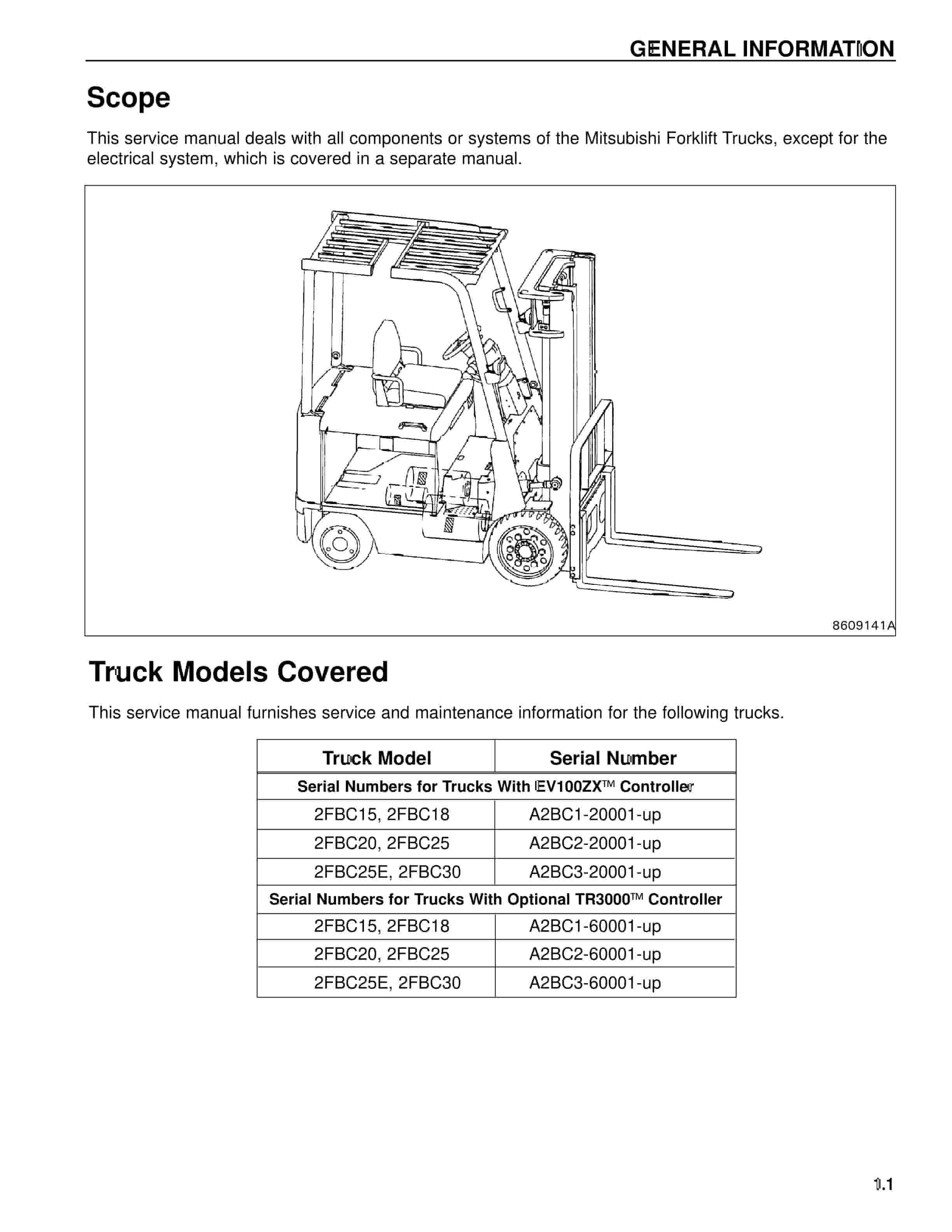
Mitsubishi 2FBC30 Forklift Service Manual
$50.00 Add to cart


%20Fuel%20System%20Supplement%20Service%20Manual%2099789-74111&url=https://ownersmanualpdf.net/docs/mitsubishi-gm-4-3l-g6-fuel-system-supplement-service-manual-99789-74111/&media=https://ownersmanualpdf.net/wp-content/uploads/2025/10/mitsubishi-gm-43l-g6-fuel-system-supplement-service-manual-99789-74111-1.jpg)
