

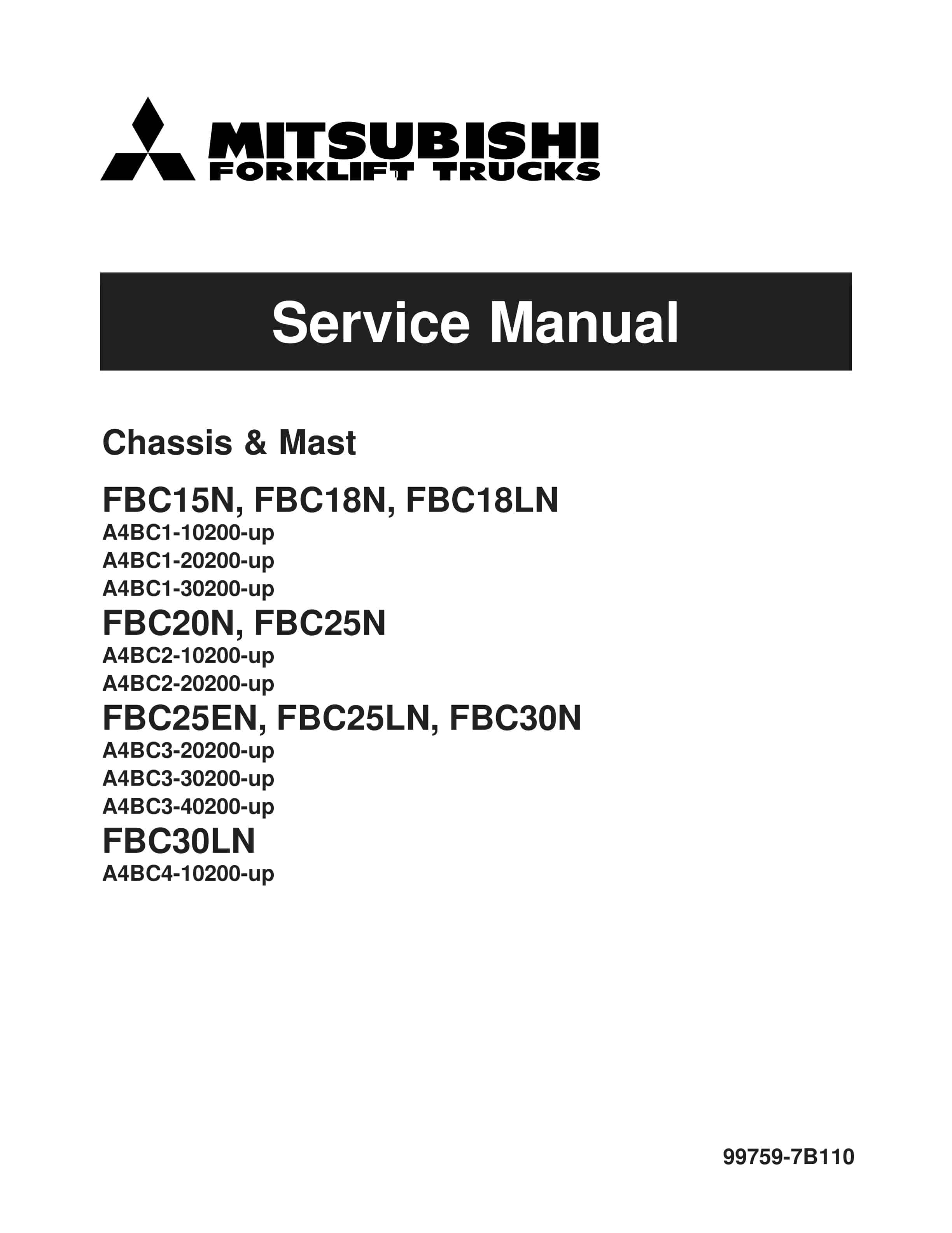
Mitsubishi FBC15N to FBC30LN Chassis and Mast Service Manual 99759-7B110
$50.00
- Type Of Manual: Service Manual
- Manual ID: 99759-7B110
- Number of Pages: 441
- Size: 8.1MB
- Format: PDF
Product details
-
Model List:
- FBC15N, FBC18N, FBC18LN, FBC20N, FBC25N, FBC25EN, FBC25LN, FBC30N, FBC30LN
- 1. Forward
- 1.1. FOREWORD
- 2. Brake System
- 2.1. Brake System
- 2.1.1. Description
- 2.1.2. Automatic Adjusting Device
- 2.1.3. Master Cylinder
- 2.1.4. Disassembly
- 2.1.5. Inspection after Disassembly
- 2.1.6. Service Brakes
- 2.1.7. Disassembly (FBC15N – FBC18LN)
- 2.1.8. Inspection after Disassembly
- 2.1.9. Reassembly (FBC15N – FBC18LN)
- 2.1.10. Wheel Cylinders
- 2.1.11. Disassembly
- 2.1.12. Inspection after Disassembly
- 2.1.13. Inspection and Adjustment
- 3. FRONT AXLE REDUCTION DIFFERENTIAL
- 3.1. FRONT AXLE REDUCTION DIFFERENTIAL
- 3.1.1. Front Axle
- 3.1.2. Removal
- 3.1.3. Installation
- 3.1.4. Disassembly
- 3.1.5. Inspection after Disassembly
- 3.1.6. Reassembly
- 3.1.7. Hub Bearing Preload
- 3.1.8. Reduction Differential
- 3.1.9. Disassembly
- 3.1.10. Inspection after Disassembly
- 3.1.11. Reassembly
- 3.1.12. Inspection and Adjustment
- 3.1.13. Tooth Contact Adjustment (FBC15N – FBC18LN)
- 4. GENERAL INFORMATION
- 4.1. GENERAL INFORMATION
- 4.1.1. Nameplate and Serial Number Locations
- 4.1.2. Dimensions
- 4.1.3. Dimensions Chart
- 4.1.4. General Information (Standard Models)
- 5. Hydraulic System
- 5.1. Hydraulic System
- 5.1.1. Description
- 5.1.2. Hydraulic Pump
- 5.1.3. Removal
- 5.1.4. Installation
- 5.1.5. Disassembly
- 5.1.6. Inspection after Disassembly
- 5.1.7. Reassembly
- 5.1.8. Inspection after Reassembly
- 5.1.9. Control Valve Removal
- 5.1.10. Control Valve Installation
- 5.1.11. Disassembly
- 5.1.12. Lift and Tilt Cylinders
- 5.1.13. Removal
- 5.1.14. Disassembly
- 5.1.15. Inspection after Disassembly
- 5.1.16. Inspection and Adjustment
- 5.1.17. Control Valve
- 5.1.18. Lift and Tilt Cylinders
- 6. Maintenance Service Data
- 6.1. Maintenance Service Data
- 6.1.1. Front Axle and Reduction Differential
- 6.1.2. Transfer Case
- 6.1.3. Rear Axle
- 6.1.4. Brake System
- 6.1.5. Steering System
- 6.1.6. Hydraulic System
- 6.1.7. Mast and Forks
- 6.1.8. Tightening Torques for Standard Bolts and Nuts
- 6.1.9. Maintenance Chart
- 6.1.10. Periodic Replacement Parts
- 6.1.11. Lubrication Chart
- 6.1.12. Fuel and Lubricant Specifications
- 6.1.13. Weight of Major Components (Approximate)
- 6.1.14. Special Service Tools
- 6.1.15. Inspection Guide
- 7. Mast and Forks
- 7.1. Mast and Forks
- 7.1.1. Description
- 7.1.2. Removal and Installation
- 7.1.3. Disassembly
- 7.1.4. Inspection after Disassembly
- 7.1.5. Reassembly
- 7.1.6. Inspection and Adjustment
- 7.1.7. Service Data
- 7.1.8. Troubleshooting
- 8. Rear Axle
- 8.1. Rear Axle
- 8.1.1. Description
- 8.1.2. Rear Wheels
- 8.1.3. Removal
- 8.1.4. Steering Cylinder
- 8.1.5. Rear Axle
- 8.1.6. Removal
- 8.1.7. Disassembly
- 8.1.8. REAR AXLE ASSEMBLY
- 8.1.9. Inspection after Disassembly
- 8.1.10. Reassembly
- 8.1.11. Inspection and Adjustment
- 8.1.12. STEERING CYLINDER
- 9. Steering Syste
- 9.1. Steering System
- 9.1.1. Description
- 9.1.2. Steering Gear
- 9.1.3. Removal
- 9.1.4. Inspection after Removal
- 9.1.5. Disassembly
- 9.1.6. Steering Gear Reassembly
- 9.1.7. Steer Pump
- 9.1.8. Removal
- 9.1.9. Disassembly
- 9.1.10. Reassembly
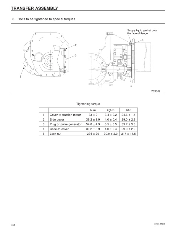
- 10. Transfer Assembly
- 10.1. Transfer Assembly
- 10.1.1. Description
- 10.1.2. Disassembly
- 10.1.3. Inspection after Disassembly
- 10.1.4. Reassembly
- 11. Troubleshooting
- 11.1. Troubleshooting
- 11.1.1. Front Axle and Reduction Differential
- 11.1.2. Brake System
- 11.1.3. Steering System
- 11.1.4. Hydraulic System
- 11.1.5. Rear Axle
- 11.1.6. Mast and Forks
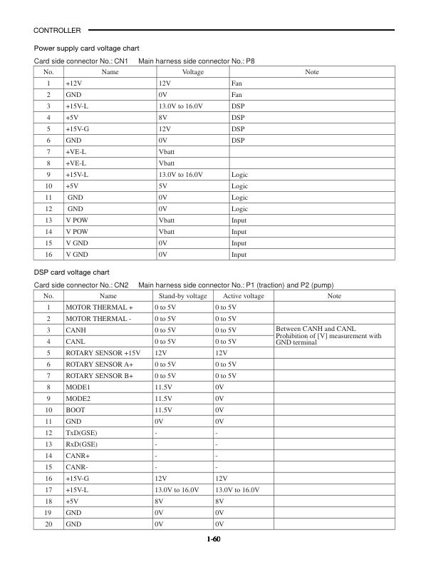
- 12. Controller
- 12.1. CONTROLLER
- 12.1.1. Controller System
- 12.1.2. Controller Features
- 12.1.3. Setup Option
- 12.1.4. Diagnosis
- 12.1.5. Removal and Installation
- 12.1.6. Basic Check
- 12.1.7. AC Motor System Basics
- 12.1.8. AC Motor Troubleshooting
- 13. Forward
- 13.1. FOREWORD
- 13.2. HOW TO USE THIS MANUAL
- 13.3. Symbols or abbreviation
- 13.3.1. Motor Installation Positions
- 13.3.2. Structures
- 13.3.3. Tightening of High-Power Motor Cable Terminals
- 13.3.4. Steer Pump Motor Removal
- 13.3.5. AC Motors
- 13.3.6. AC Pump Motor
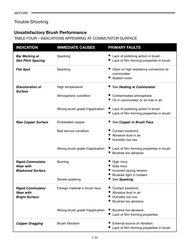
- 13.3.7. Trouble Shooting
- 13.3.8. Service Data
- 14. TROUBLESHOOTING FOR CONTROL CIRCUITS
- 14.1. TROUBLESHOOTING FOR CONTROL CIRCUITS
- 14.1.1. General Information
- 14.1.2. Problem Traction Motor, Overheating (E0)
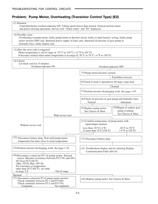
- 14.1.3. Problem Pump Motor, Overheating (Transistor Control Type) (E2)
- 14.1.4. Problem Pump Motor, Overheating (Contactor Control Type) (E2)
- 14.1.5. Problem Traction Inverter, Overheating (E5)
- 14.1.6. Problem Pump Inverter, Overheating (Transistor Control Type Only) (E7)
- 14.1.7. Problem Brake Oil, Low Level
- 14.1.8. Problem Pump Motor, Worn Brushes (Contactor Control Type Only) (br)
- 14.1.9. Problem Traction Motor Current Sensor Fault (14)
- 14.1.10. Problem Traction Motor, Over-current (15)
- 14.1.11. Problem Traction Motor, Stall Timer (16)
- 14.1.12. Problem Pump Motor Current Sensor Fault (Transistor Control Type Only) (34)
- 14.1.13. Problem Pump Motor Over-current (Transistor Control Type Only) (35)
- 14.1.14. Problem Line Contactor Fault (40)
- 14.1.15. Problem Steering Contactor Fault (41)
- 14.1.16. Problem Pump Contactor Fault (Contactor Control Type Only) (42)
- 14.1.17. Problem Traction Motor Open (45)
- 14.1.18. Problem Pump Motor Open (Transistor Control Type Only) (47)
- 14.1.19. Problem Accelerator Sensor Fault (51)
- 14.1.20. Problem Traction Motor Pulse Input Fault (52)
- 14.1.21. Problem Pump Motor Pulse Input Fault (Transistor Control Type Only) (57)
- 14.1.22. Problem Display Communication Fault (60)
- 14.1.23. Problem Logic Card Initialize Failure (61)
- 14.1.24. Problem Logics Fault (62)
- 14.1.25. Problem Traction Inverter Fault (63)
- 14.1.26. Problem Pump Inverter Fault (Transistor Control Type Only) (65)
- 14.1.27. Problem Contactor Coil Fault (72)
- 14.1.28. Problem Hydraulic Lock Solenoid Fault (74)
- 14.1.29. Problem Electromagnetic Brake Solenoid Fault (75)
- 14.1.30. Problem Battery Voltage Too Low (78)
- 14.1.31. Problem Battery Voltage Too High (79)
- 14.1.32. Problem Direction Lever or Accelerator, Faulty Setting (E)
- 14.1.33. Problem Seat Switch, Faulty Setting For Traction ((E))
- 14.1.34. Problem Seat Switch, Faulty Setting For Hydraulic ((L))
- 14.1.35. Problem Lift Lever, Faulty Setting (H1)
- 14.1.36. Problem Tilt Lever, Faulty Setting (H2)
- 14.1.37. Problem Attachment 1 Lever, Faulty Setting (H3)
- 14.1.38. Problem Battery Consumption Too Much ((Lo))
- 14.1.39. Problem Battery Consumption
Related products
-
Mitsubishi 4DQ7, S4S Diesel Engine Service Manual
$50.00 Add to cart -
Mitsubishi 4DQ5, S4E, S4E2 Diesel Engine Service Manual
$50.00 Add to cart -
Mitsubishi 1204E Diesel Engine Systems Operation Testing and Adjusting Service Manual 99799-56103
$50.00 Add to cart -
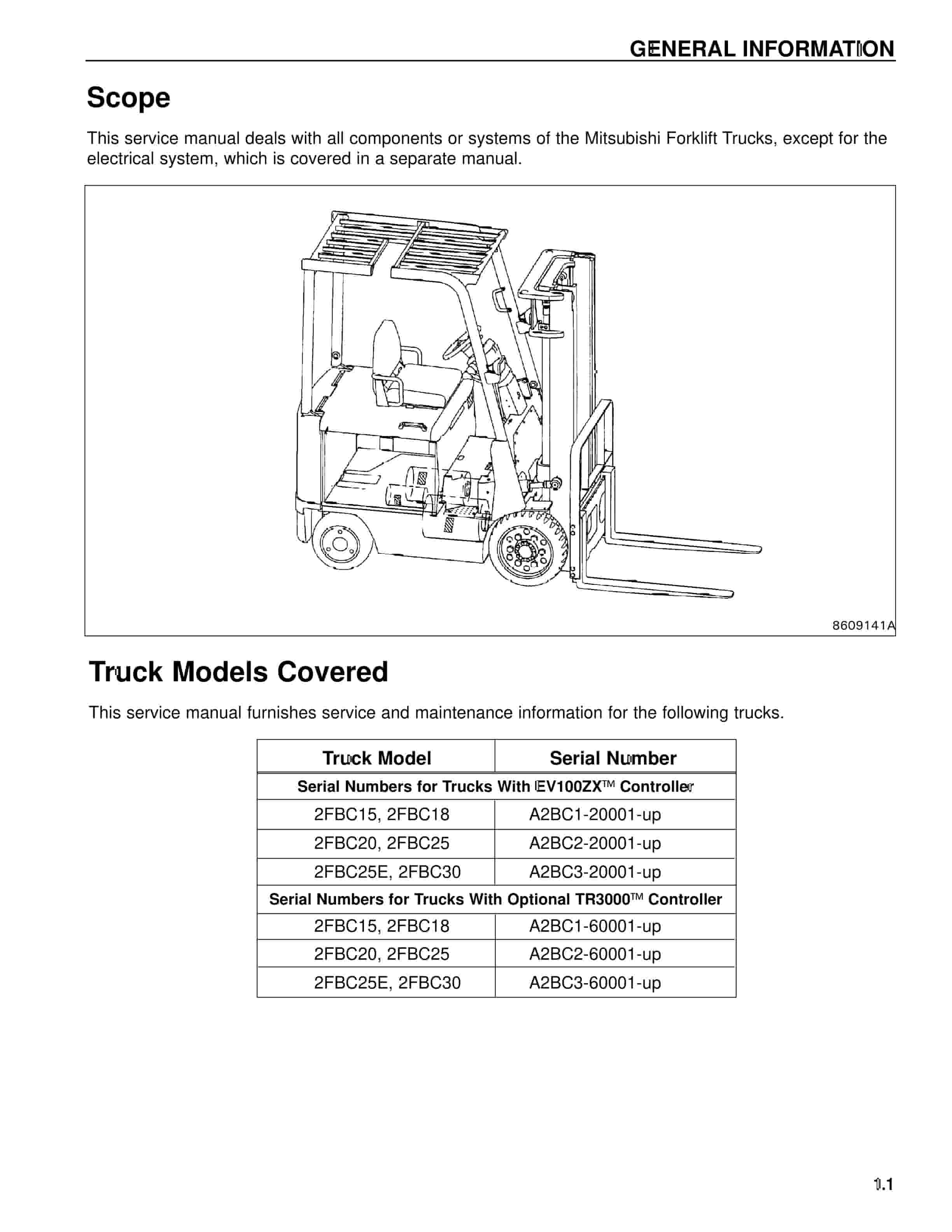
Mitsubishi 2FBC15 Forklift Service Manual
$50.00 Add to cart -
Mitsubishi 4DQ5, S4E, S6E, S6E2 Service Manual 99719-52120
$50.00 Add to cart


