

Mitsubishi K21, K25 Engine Service Manual 99789-55101
$50.00
- Type Of Manual: Service Manual
- Manual ID: 99789-55101
- Number of Pages: 232
- Size: 5.5MB
- Format: PDF
Product details
-
Model List:
- K21 Engine, K25 Engine
- 1. How to use this manual
- 1.1. Description
- 1.2. Definition of Terms
- 1.3. Definition of Units
- 1.4. Description
- 2. Precautions for safety and quality
- 2.1. Reduction of Risk Operation
- 2.2. Correct Operation
- 2.3. Precautions for Radio Equipment Installation
- 3. Precautions
- 3.1. Precautions in Draining Engine Coolant
- 3.2. Precautions for Disconnecting Fuel Piping
- 3.3. Precautions for Removing and Disassembling
- 3.4. Precautions for Inspection, Correction, and Replacement
- 3.5. Precautions for Assembly and Installation
- 3.6. Parts Requiring Angle Tightening
- 3.7. Caution for Use of Power Tools
- 3.8. Precautions for Liquid Gasket Application
- 4. Tightening torque
- 4.1. Standard Bolt Tightening Torque
- 4.2. Engine Part Tightening Torque
- 5. Special Service Tools
- 6. Engine outside drawings
- 7. Standard and repair limit
- 8. Trouble diagnosis
- 8.1. Engine Adjustment
- 8.2. Engine LPG Fuel System
- 9. Engine maintenance
- 9.1. Specifications
- 9.2. Tightening Torque
- 9.3. Maintenance Schedule
- 9.4. Oil and Grease, and Capacity
- 9.5. On Board Inspection and Service
- 10. Specifications
- 11. Tightening torque
- 12. Trouble diagnosis
- 13. ENGINE INSPECTION AND ADJUSTMENT
- 13.1. Engine Body Related
- 13.2. Ignition and Fuel Systems
- 14. SERVICE DATA AND SPECI FICATIONS (SDS)
- 14.1. Electronic Control System Specifications
- 15. Precautions
- 15.1. Precautions for Draining Engine Coolant
- 15.2. Precautions for Disconnecting Fuel Piping
- 15.3. Precautions for Removing and Disassembling
- 15.4. Precautions for Inspection, Correction, and Replacement
- 15.5. Precautions for Assembly and Installation
- 15.6. Parts Requiring Angle Tightening
- 15.7. Caution for Use of Power Tools
- 15.8. Precautions for Liquid Gasket Application
- 16. Engine outside drawings
- 17. Adjustment value
- 18. Tightening torque
- 18.1. Standard Bolt Tightening Torque
- 18.2. Engine Part Tightening Torque
- 19. Trouble diagnosis
- 20. Special Service Tools
- 21. Removal and installation of engine
- 21.1. Removal
- 21.2. Installation
- 21.3. Inspection
- 22. Engine service
- 22.1. Engine Disassembly
- 22.2. Inspection and Correction
- 22.3. Engine Assembly
- 23. Precautions
- 23.1. General precautions for service operations
- 24. Preparation
- 24.1. Service Tools
- 25. Description
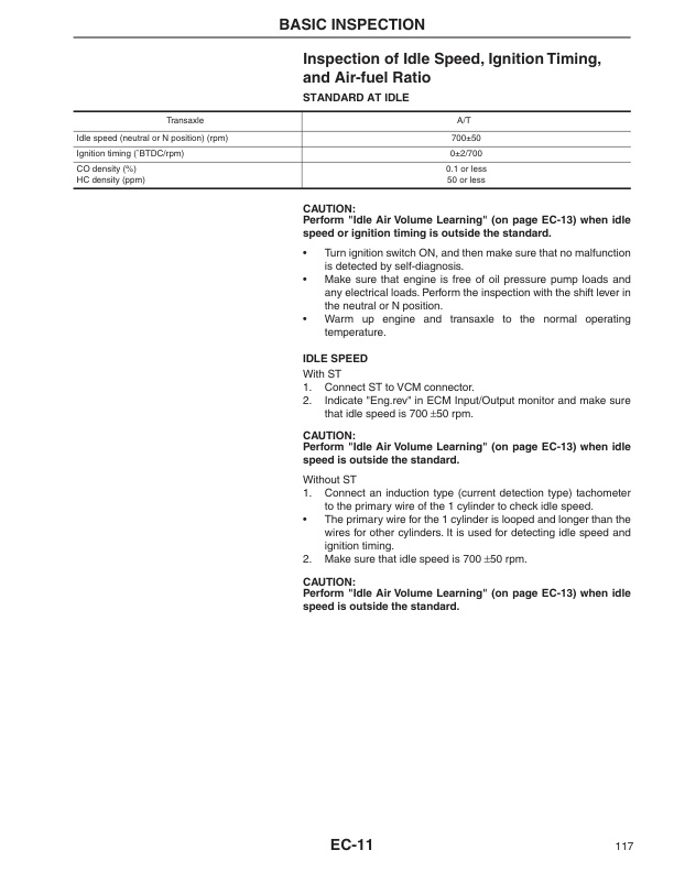
- 26. Basic inspection
- 26.1. Inspection of Idle Speed, Ignition Timing, and Air-fuel Ratio
- 26.2. Throttle Valve Closed Position Learning and Idle Air Volume Learning
- 26.3. Accelerator Pedal Released Position Learning
- 26.4. Fuel pressure inspection
- 27. Trouble Diagnosis
- 27.1. How to Proceed with Trouble Diagnosis
- 27.2. Diagnosis Chart by Symptom
- 27.3. Component Parts Location
- 27.4. ECM Component
- 27.5. Circuit Diagram
- 27.6. ECM Terminal Layout
- 27.7. ECM Input/Output Signal Specifications
- 27.8. Service Tool (ST)
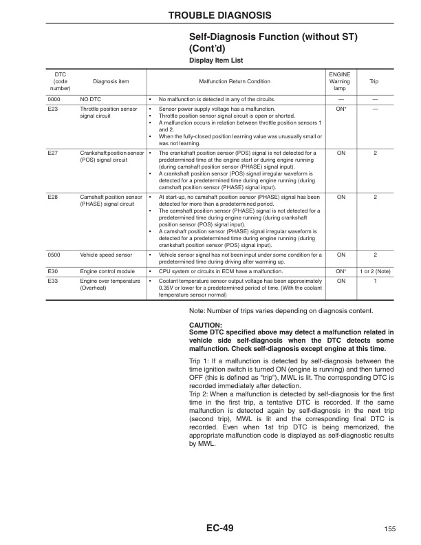
- 27.9. Self-Diagnosis Function (without ST)
- 27.10. ST Reference Value in Data Monitor
- 27.11. Fail-Safe Function
- 28. Power supply and ground system
- 28.1. ECM Input/Output Signal Specifications
- 28.2. Circuit Diagram
- 29. Crankshaft position sensor (POS) sys tem
- 29.1. ECM Input/Output Signal Specifications
- 29.2. Circuit Diagram
- 29.3. Component Parts Inspection
- 30. Camshaft position sen sor (PHASE) system
- 30.1. ECM Input/Output Signal Specifications
- 30.2. Circuit Diagram
- 30.3. Component Parts Inspection
- 31. Mass air flow sensor system
- 31.1. ST Data Monitor Display
- 31.2. ECM Input/Output Signal Specifications
- 31.3. Circuit Diagram
- 31.4. Component Parts Inspection
- 32. Engine coolant tempera ture sensor system
- 32.1. ST Data Monitor Display
- 32.2. ECM Input/Output Signal Specifications
- 32.3. Circuit Diagram
- 32.4. Component Parts Inspection
- 33. Heated oxygen sensor system
- 33.1. ST Data Monitor Display
- 33.2. ECM Input/Output Signal Specifications
- 33.3. Circuit Diagram
- 34. Throttle position sensor system
- 34.1. ST Data Monitor Display
- 34.2. ECM Input/Output Signal Specifications
- 34.3. Circuit Diagram
- 34.4. Component Parts Inspection
- 35. Accelerator pedal position sensor system
- 35.1. ST Data Monitor Display
- 35.2. ECM Input/Output Signal Specifications
- 35.3. Circuit Diagram
- 35.4. Component Parts Inspection
- 36. Intake air temperature sensor
- 36.1. ST Data Monitor Display
- 36.2. ECM Input/Output Signal Specifications
- 36.3. Circuit Diagram
- 36.4. Component Parts Inspection
- 37. PNP switch system
- 37.1. ST Data Monitor Display
- 37.2. ECM Input/Output Signal Specifications
- 37.3. Circuit Diagram
- 38. Stop lamp switch system
- 38.1. ST Data Monitor Display
- 38.2. ECM Input/Output Signal Specifications
- 38.3. Circuit Diagram
- 38.4. Component Parts Inspection
- 39. Electric load switch system
- 39.1. ST Data Monitor Display
- 39.2. ECM Input/Output Signal Specifications
- 39.3. Circuit Diagram
- 40. CAN communication system
- 40.1. ECM Input/Output Signal Specifications
- 40.2. Circuit Diagram
- 41. Ignition system
- 41.1. ST Data Monitor Display
- 41.2. ECM Input/Output Signal Specifications
- 41.3. Circuit Diagram
- 41.4. Component Parts Inspection
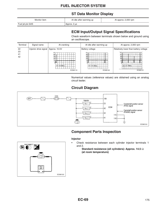
- 42. Fuel injector system
- 42.1. ST Data Monitor Display
- 42.2. ECM Input/Output Signal Specifications
- 42.3. Circuit Diagram
- 42.4. Component Parts Inspection
- 43. Fuel pump system
- 43.1. ST Data Monitor Display
- 43.2. ECM Input/Output Signal Specifications
- 43.3. Circuit Diagram
- 43.4. Component Parts Inspection
- 44. Throttle control motor system
- 44.1. ECM Input/Output Signal Specifications
- 44.2. Circuit Diagram
- 44.3. Component Parts Inspection
- 45. Heated oxygen sensor heater system
- 45.1. ST Data Monitor Display
- 45.2. ECM Input/Output Signal Specifications
- 45.3. Circuit Diagram
- 45.4. Component Parts Inspection
- 46. PCV gas recirculation device
- 46.1. System Diagram
- 46.2. Component Parts Inspection
- 47. Fuel cut function
- 47.1. Inspection Procedure
- 48. Removal and installation of ECM components
- 48.1. Removal and Installation of ECM
- 48.2. Removal and Installation of Crankshaft Position Sensor (POS)
- 48.3. Removal and Installation of Camshaft Position Sensor (PHASE)
- 48.4. Removal and Installation of Mass Air Flow Sensor
- 48.5. Removal and Installation of Engine Coolant Temperature Sensor.
- 48.6. Removal and Installation of Heated Oxygen Sensor (with Heated Oxygen Sensor Heater)
- 48.7. Removal and Installation of Throttle Position Sensor (Electric Throttle Control Actuator Assembly)
- 48.8. Removal and Installation of Accelerator Pedal Position Sensor (Accelerator Pedal Assembly)
- 48.9. Removal and Installation of Intake Air Temperature Sensor (with Mass Air Flow Sensor)
- 48.10. Removal and Installation of Neutral Switch (M/T Model)
- 48.11. Removal and Installation of Ignition Coil (with Power Transistor)
- 48.12. Removal and Installation of Fuel Injector
- 48.13. Removal and Installation of Fuel Pump
- 48.14. Removal and Installation of Throttle Control Motor (Electric Throttle Control Actuator Assembly)
- 48.15. Removal and Installation of LPG Injector Holder
- 48.16. Removal and Installation of LPG Injector Drive Unit
- 49. SERVICE DATA AND SPECIFICATIONS (SDS)
- 49.1. Standard, Repair Limit
- 50. Lubrication system
- 50.1. Specifications
- 50.2. Adjustment Value
- 50.3. Oil Pressure
- 50.4. Tightening Torque
- 50.5. Trouble Diagnosis
- 50.6. Lubrication Schematic Diagram
- 50.7. Oil Pump
- 51. Engine coolant system
- 51.1. Specifications
- 51.2. Adjustment Value
- 51.3. Tightening Torque
- 51.4. Trouble Diagnosis
- 51.5. Cooling System Configuration
- 51.6. Water Pump
- 51.7. Thermostat
- 51.8. Thermostat
- 52. Emission control system (only for electronic controlled type)
- 53. Unit layout
- 54. LPG fuel system trouble diagnosis
- 55. Disassembly and assembly of fuel system
- 55.1. Removal and Installation of LPG Injector Drive Unit Connector
- 55.2. Removal and Installation of Electronic Control Throttle Assembly
- 55.3. Removal and Installation of Gasoline Fuel Injector (Electronic Controlled Gasoline and Combined Use)
- 55.4. Injector Holder
- 56. Vaporizer mechanism and operation
- 56.1. Primary (Decompression) Room
- 56.2. Description
- 57. Adjustment value
- 58. Trouble diagnosis
- 59. Starter motor
- 59.1. Starter Motor Specifications
- 59.2. Component Parts Location
- 59.3. Overhaul
- 59.4. Assembly Inspection
- 60. Alternator
- 60.1. Components of Alternator
- 60.2. Disassembly
- 60.3. Inspection
Related products
-
Mitsubishi 4G33, 4G52, 4G54 Service Manual 99719-42120
$50.00 Add to cart -
Mitsubishi FB16NT, FB18NT, FB20NT Chassis, Mast and Options Service Manual 99719-78100
$50.00 Add to cart -
Mitsubishi 4G63, 4G64 Fuel System Supplement Service Manual 99729-75110
$50.00 Add to cart -
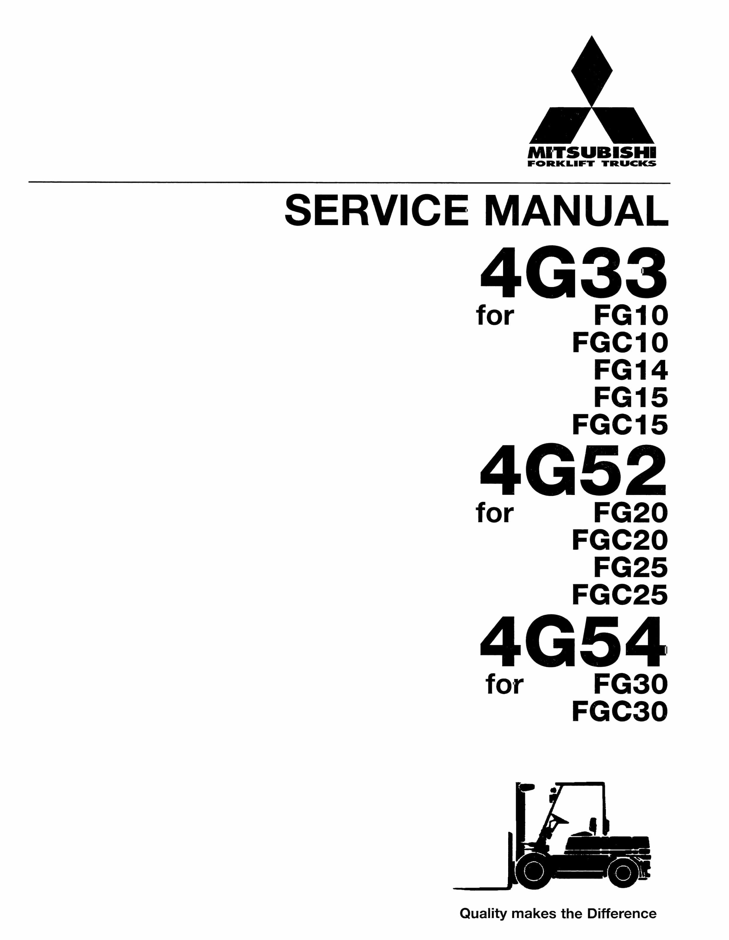
Mitsubishi 4G33, 4G52, 4G54 Service Manual 99719-41111
$50.00 Add to cart -
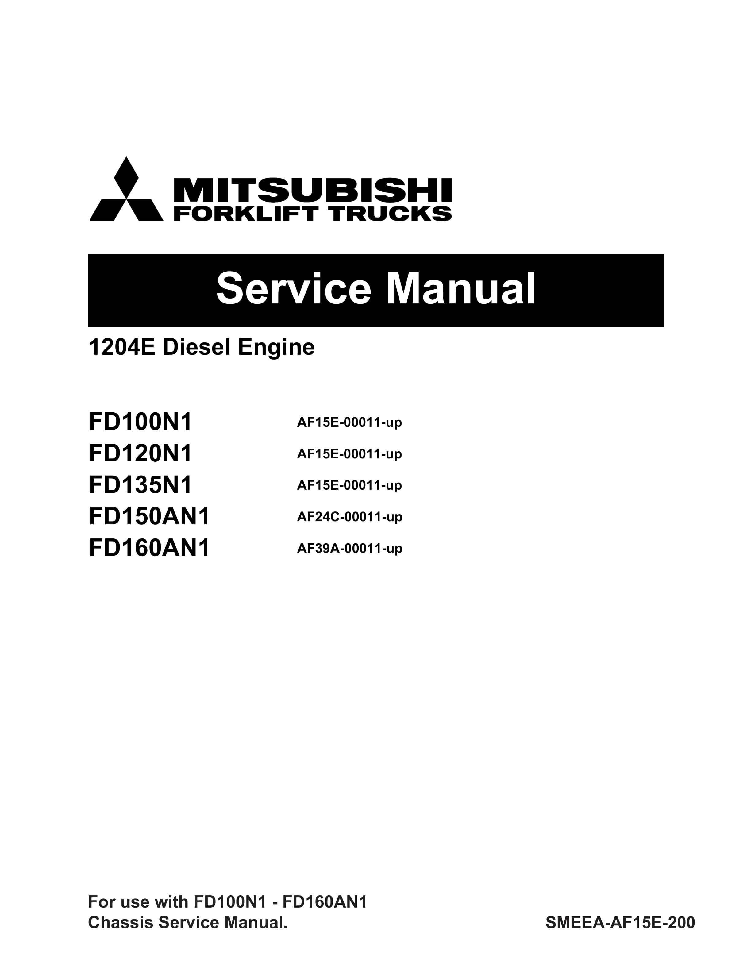
Mitsubishi 1204E Diesel Engine Service Manual SMEEA-AF15E-200
$50.00 Add to cart


