
(C),%20RB16-20N3,%20RB16-25N3H(X),%20RBM20-25N3,%20THD13-15N3%20Service%20Manual%20SM21GBRE1AA3&url=https://ownersmanualpdf.net/docs/mitsubishi-rb12-14n3lc-rb16-20n3-rb16-25n3hx-rbm20-25n3-thd13-15n3-service-manual-sm21gbre1aa3/&media=https://ownersmanualpdf.net/wp-content/uploads/2025/10/mitsubishi-rb12-14n3lc-rb16-20n3-rb16-25n3hx-rbm20-25n3-thd13-15n3-service-manual-sm21gbre1aa3-1.jpg)
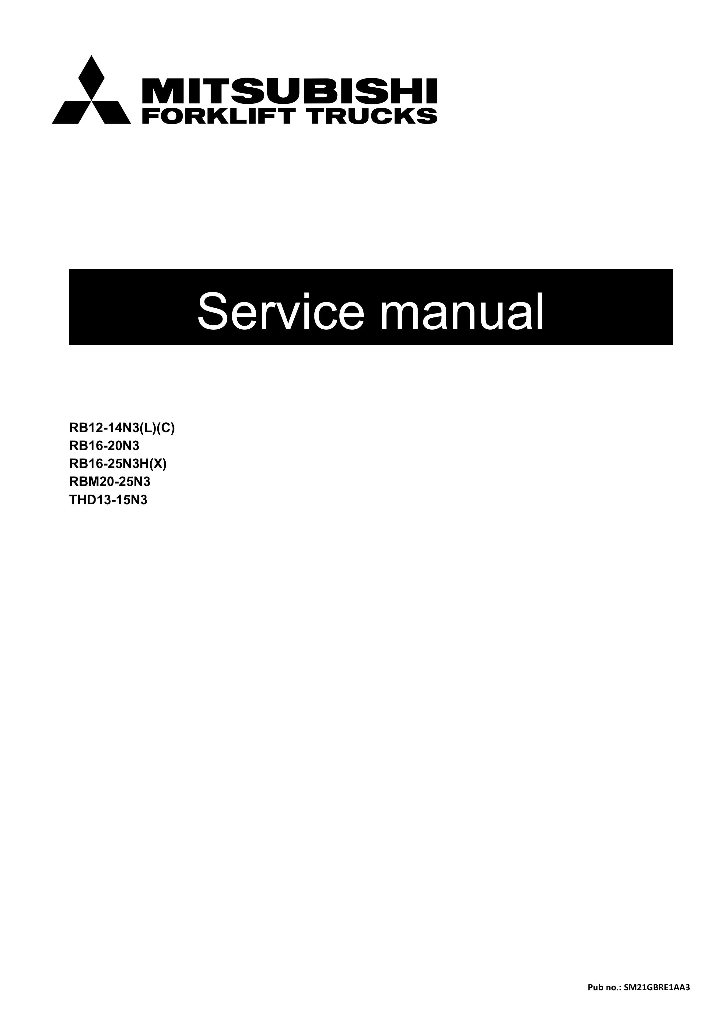
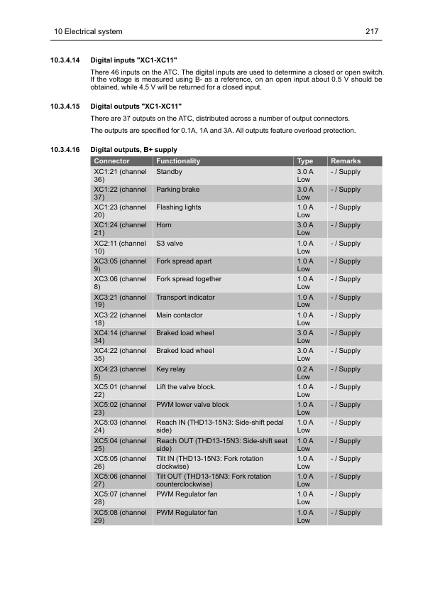
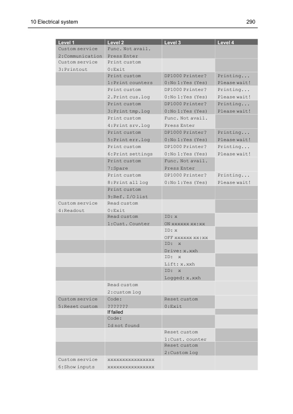
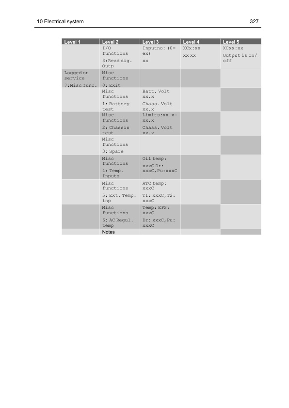
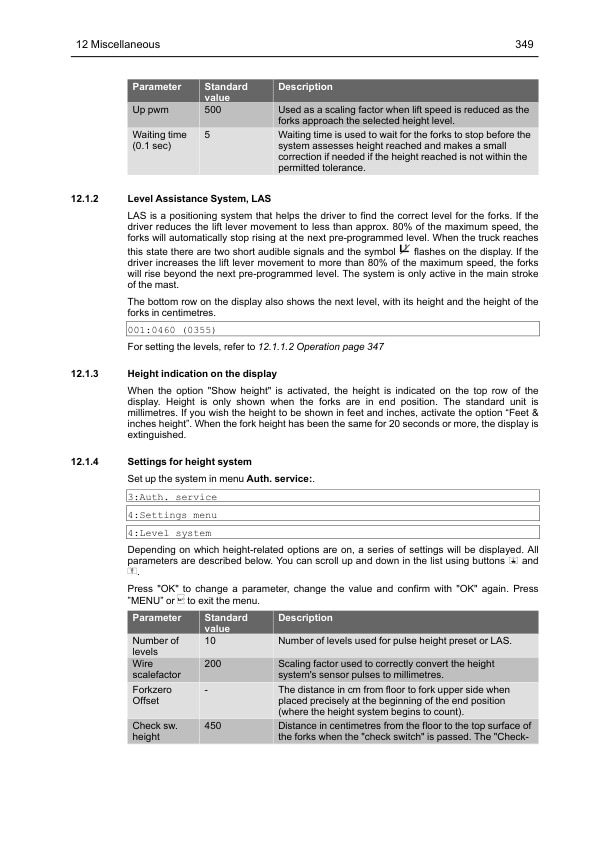
Mitsubishi RB12-14N3(L)(C), RB16-20N3, RB16-25N3H(X), RBM20-25N3, THD13-15N3 Service Manual SM21GBRE1AA3
$50.00
- Type Of Manual: Service Manual
- Manual ID: SM21GBRE1AA3
- : 2
- Number of Pages: 440
- Size: 11.8MB
- Format: PDF
Product details
-
Model List:
- RB12-14N3(L)(C), RB16-20N3, RB16-25N3H(X), RBM20-25N3, THD13-15N3
- 1. GENERAL INFORMATION AND TECHNICAL DATA
- 1.1. Introduction
- 1.1.1. General
- 1.1.2. The trucks
- 1.1.3. Genuine Parts
- 1.1.4. Authorised service personnel
- 1.1.5. Symbol key
- 1.2. Safety
- 1.2.1. General
- 1.2.2. Safety instructions
- 1.2.3. Truck modification
- 1.2.4. Lifting the truck
- 1.2.5. Towing/moving non-powered RBM20-25N3
- 1.2.6. Welding on truck
- 1.3. Environmental considerations
- 1.3.1. We respect the environment
- 1.4. Preparations
- 1.4.1. Service
- 1.4.2. Troubleshooting
- 1.5. Truck data
- 1.5.1. Machine plates
- 1.5.2. Type designation
- 1.5.3. Truck types
- 1.6. Component specification
- 1.6.1. Drive motor
- 1.6.2. Electric brake
- 1.6.3. Gearbox
- 1.6.4. Hydraulic unit
- 1.6.5. Control system for traction and pump motors
- 1.6.6. Steering servo motor
- 1.6.7. Controller system for steering
- 1.7. Recommended consumable materials
- 1.7.1. Oil and grease types
- 1.8. Standards and abbreviations
- 1.8.1. General
- 1.8.2. Screw types and tensile grades
- 1.8.3. Tightening torques for screws and nuts
- 1.8.4. Tightening torque for hydraulic couplings
- 1.8.5. Tightening torque for banjo screws with rubber-steel washer
- 1.8.6. Tightening torque, conversion table
- 1.9. Code explanations
- 1.9.1. Colour codes for wiring diagrams
- 1.9.2. Designations for electrical components in electrical diagram
- 1.9.3. Standard abbreviations and units
- 1.9.4. Acronyms and abbreviations
- 2. SPECIAL TOOLS
- 2.1. List of tools
- 3. SERVICE
- 3.1. Service inspection
- 3.1.1. Daily/Weekly inspection
- 3.1.2. General
- 3.1.3. First service (200 hours)
- 3.1.4. Service intervals
- 3.1.5. Verification of safety functions
- 3.1.6. Check list
- 3.2. Lubrication
- 3.2.1. Symbol key lubrication chart
- 3.2.2. Lubrication chart RB12-14N3(L)(C) / RB16-20N3 / RB16-25N3H(X)
- 3.2.3. Lubrication chart RBM20-25N3
- 3.2.4. Lubrication chart THD13-15N3
- 3.2.5. Tri-lateral head maintenance schedule
- 3.2.6. Cab lubrication schematic diagram (option)
- 4. CHASSIS
- 4.1. Design and function
- 4.1.1. Chassis frame
- 4.1.2. Machine housing
- 4.1.3. Overhead guard
- 4.1.4. Battery locking
- 4.1.5. Armrest and steering wheel
- 4.1.6. Foot plate
- 4.1.7. Covers and panels
- 4.1.8. Tightening torque for chassis plates
- 4.2. Repair and maintenance instructions
- 4.2.1. Panels
- 4.2.2. Load wheels
- 4.2.3. Machine housing
- 4.2.4. Adjusting the stabilising lugs (RB16-25N3H(X))
- 4.2.5. Driver seat
- 4.2.6. Overhead guard
- 4.2.7. Batteries
- 4.2.8. Battery rollers
- 4.2.9. Adjustable armrest
- 4.2.10. Fitting the antistatic chain
- 5. DRIVE UNIT
- 5.1. Design and function
- 5.1.1. Drive motor
- 5.1.2. Gearbox
- 5.2. Repair and maintenance instructions
- 5.2.1. Before work is performed
- 5.2.2. Drive unit
- 5.2.3. Traction motor
- 5.2.4. Removal and installation of the traction motor
- 5.2.5. First service
- 5.2.6. Preventive maintenance
- 5.2.7. Reconditioning the traction motor
- 5.2.8. Gearbox
- 5.2.9. Drive wheel
- 5.3. Diagnostics and troubleshooting
- 5.3.1. Troubleshooting chart
- 6. MAST SYSTEM
- 6.1. Design and function
- 6.1.1. Mast system
- 6.1.2. Fork carriage
- 6.2. Repair and maintenance instructions
- 6.3. Lift cylinders
- 6.3.1. Adjustment of the cylinder attachments in the mast
- 6.4. Lift chains
- 6.4.1. Checking the lift chains
- 6.4.2. Adjusting the lift chains
- 6.4.3. Routine periodic maintenance
- 6.4.4. Mounting chains
- 6.5. Reach carriage
- 6.5.1. Removal and installation of the mast with carriage
- 6.5.2. Adjusting the reach carriage
- 6.6. Fork carriage
- 6.6.1. Removal and installation of the fork carriage
- 6.6.2. Adjusting the fork carriage
- 6.6.3. Inspection and adjustment of the rubber shock absorbers on the forklift, THD13-15N3
- 6.6.4. Inspection of forged forks
- 6.7. Side shift unit of hanging type
- 6.7.1. Preventive maintenance
- 6.7.2. Check of cylinders
- 6.8. Integrated side shift unit (ISS)
- 6.8.1. Preventive maintenance
- 6.8.2. Removal and installation of the unit (ISS)
- 6.8.3. Removing the sliding pads
- 6.8.4. Dismantling the cylinder
- 6.9. Integral Fork positioner/sideshift, RB12-14N3(L)(C), RB16-20N3, RB16N3H, RB20N3H
- 6.9.1. General
- 6.9.2. Dismantling and fitting the forks
- 6.9.3. Replacing the bushings
- 6.9.4. Replacing the slide plate
- 6.9.5. Dismounting the hydraulic cylinder
- 6.9.6. Repacking the hydraulic cylinder
- 6.9.7. Cleaning the flow divider
- 6.10. Integral Fork positioner/sideshift, RB25N3H
- 6.10.1. General
- 6.10.2. Dismantling and fitting the forks
- 6.10.3. Replacing the bushings
- 6.10.4. Replacing the fork support rollers
- 6.10.5. Dismounting the hydraulic cylinder
- 6.10.6. Repacking the hydraulic cylinder
- 6.10.7. Cleaning the flow divider
- 6.11. Hydraulic fork spreading, RBM20-25N3
- 6.11.1. General
- 6.11.2. Lifting the unit.
- 6.11.3. Adjusting the fork angle, RBM20-25N3
- 6.11.4. Maintenance
- 6.12. Swivel forks unit (THD13-15N3)
- 6.12.1. General
- 6.12.2. Safety instructions
- 6.12.3. Machine plate
- 6.12.4. Lifting the tri-lateral head
- 6.12.5. Installing the swivel forks unit
- 6.12.6. Removing the swivel forks unit
- 6.12.7. Maintenance
- 6.12.8. Trouble shooting
- 6.13. Diagnostics and trouble shooting
- 6.13.1. Troubleshooting chart (Triplex with free lift, Duplex)
- 6.13.2. Troubleshooting chart for the side shift unit of hanging type (Duplex)
- 6.13.3. Troubleshooting chart for the integrated side shift unit (ISS) (Triplex with free lift)
- 6.13.4. Troubleshooting chart for Integral Fork positioner/sideshift, (Triplex with free lift)
- 6.13.5. Fault-finding chart for fork spreaders (RBM20-25N3)
- 7. STEERING
- 7.1. Design and function
- 7.1.1. General
- 7.1.2. Steering
- 7.1.3. Steering servo motor controller
- 7.2. Repair and maintenance instructions
- 7.2.1. Steering wheel
- 7.2.2. Steering servo motor
- 7.2.3. Settings, adjustments and testing
- 7.2.4. Options
- 7.3. Diagnostics and troubleshooting
- 7.3.1. Troubleshooting chart
- 8. HYDRAULIC SYSTEM
- 8.1. Design and function
- 8.1.1. Description
- 8.1.2. Hose rupture valve
- 8.1.3. Electric proportional valve
- 8.1.4. Electric solenoid valve
- 8.1.5. MTC (Mast Tilt Control)
- 8.1.6. Hydraulic diagram
- 8.2. Maintenance and repair instructions
- 8.2.1. General rules
- 8.2.2. Installation
- 8.2.3. Connections
- 8.2.4. Dismantling and assembling hydraulic hoses
- 8.2.5. Pump motor
- 8.2.6. Hydraulic oil tank
- 8.2.7. MTC (Mast Tilt Control)
- 8.3. Control valve
- 8.3.1. Operation of the control valve
- 8.3.2. Control valve overview
- 8.3.3. Removal and installation of the control valve
- 8.3.4. Adjusting the working pressure
- 8.3.5. Inspection and adjustment of the lowering rate
- 8.3.6. Calibrating the hydraulic functions
- 8.3.7. S3 valve
- 8.3.8. Emergency lowering valve
- 8.3.9. Hose rupture valve
- 8.4. Control valve (THD13-15N3)
- 8.4.1. Operation of the control valve
- 8.4.2. Control valve overview
- 8.4.3. Removal and installation of the control valve
- 8.4.4. Adjusting the working pressure
- 8.4.5. Inspection and adjustment of the lowering rate
- 8.5. Diagnostics and troubleshooting
- 8.5.1. Troubleshooting the hydraulic system
- 8.5.2. Troubleshooting chart
- 8.5.3. Troubleshooting the control valve
- 8.5.4. Troubleshooting, sensors S21 and S22
- 9. HYDRAULIC CYLINDERS
- 9.1. Design and function
- 9.1.1. Mast shift cylinder
- 9.1.2. Tilt cylinder
- 9.1.3. Free lift cylinder
- 9.1.4. Final stroke cylinder
- 9.2. Repair and maintenance instructions
- 9.2.1. General
- 9.2.2. Reach cylinder
- 9.2.3. Tilt cylinder
- 9.2.4. Free lift cylinder
- 9.2.5. Final stroke cylinder
- 9.2.6. Removal and installation of the gasket in the hydraulic cylinder
- 10. ELECTRICAL SYSTEM
- 10.1. Introduction
- 10.1.1. Description of components
- 10.2. Safety
- 10.2.1. Safety instructions
- 10.2.2. Electronic controllers
- 10.2.3. Safety checks
- 10.2.4. Steering servo system
- 10.2.5. Traction system
- 10.2.6. Hydraulic system
- 10.3. Design and function
- 10.3.1. Battery
- 10.3.2. Battery capacity measurement
- 10.3.3. Battery parameters
- 10.3.4. Truck computer ATC
- 10.4. Repair and maintenance instructions
- 10.4.1. Traction and pump regulation
- 10.4.2. Insulation resistance
- 10.4.3. Temperature measurement and management
- 10.4.4. System for detecting the carriage position
- 10.4.5. Electrical monitoring of battery locking
- 10.5. Diagnostics and troubleshooting
- 10.5.1. Troubleshooting of the hydraulic functions, channels 3, 4 and 5
- 10.5.2. Troubleshooting of the hydraulic functions, channels 1, 2 and 3
- 10.5.3. General instructions for all types of faults in combination with a loss of voltage
- 10.5.4. Truck computer ATC
- 10.5.5. ATC error codes
- 10.5.6. ATC, warnings
- 10.5.7. Troubleshooting – operational disturbances
- 10.5.8. Troubleshooting table – battery
- 10.5.9. Enclosure
- 11. SPEED CONTROL AND BRAKE SYSTEMS
- 11.1. Design and function
- 11.1.1. Electric brake
- 11.1.2. Speed and brake sensor
- 11.1.3. Hill hold
- 11.2. Repair and maintenance instructions
- 11.2.1. Electric brakes
- 11.2.2. Brake Pedal Assembly
- 11.2.3. Left-foot switch
- 11.2.4. Speed Controller
- 11.3. Diagnostics and troubleshooting
- 11.3.1. Brake troubleshooting
- 12. MISCELLANEOUS
- 12.1. Level selector and height indication
- 12.1.1. Pulse height preset
- 12.1.2. Level Assistance System, LAS
- 12.1.3. Height indication on the display
- 12.1.4. Settings for height system
- 12.1.5. Checking the fork offset
- 12.2. Example of use
- 12.2.1. Ex.1 Collecting a load
- 12.2.2. Ex.2 Just logged on
- 12.2.3. Ex.3 Placing the load
- 12.3. Stability Support System, S3-1
- 12.3.1. Identification
- 12.3.2. Functionality, S3-1
- 12.3.3. Drive Speed
- 12.3.4. Hydraulic functions
- 12.3.5. Technical description
- 12.4. Smart card
- 12.5. Weight system
- 12.5.1. Introduction
- 12.5.2. Accompanying hardware
- 12.5.3. S3-2 Speed and weight alternatives
- 12.5.4. Weight indication
- 12.5.5. Side effects, Weight system
- 12.5.6. Calibrating the Weight system
- 12.5.7. Diagnostics menu
- 12.6. Rail guided steering
- 12.6.1. General
- 12.6.2. Installation
- 12.6.3. Dismantling and fitting the rail guide wheel
- 12.6.4. Adjusting the sensor
- 12.6.5. Straight driving mode, audible and light signals
- 12.6.6. Speed limits
- 12.6.7. Adjusting max. speed
- 12.7. Wire guidance
- 12.7.1. Wire guidance antenna
- 12.7.2. Fitting/removing antennae for wire guidance
- 12.7.3. Setting the wire guidance.
- 12.7.4. Calibrating wire guidance.
- 12.7.5. Manual calibration of wire guidance.
- 12.7.6. Troubleshooting for wire guidance
- 12.8. End of Aisle magnetic system
- 12.8.1. Introduction to End of Aisle magnetic system
- 12.8.2. Installation of End of Aisle magnetic system
- 12.8.3. End of Aisle magnetic system settings
- 12.8.4. End of Aisle magnetic system troubleshooting
- 12.9. Collision sensor
- 12.10. Service indication
- 12.11. Trucks equipped with restart
- 12.12. Hand-controlled direction selector
- 12.13. Side shift and tilt centring
- 12.14. Speed reduction
- 12.15. Automatic logging off
- 12.16. Buzzer when the battery voltage is low
- 12.17. Straddle leg monitor (RBM20-25N3)
- 12.18. Load wheel covers
- 12.18.1. Installation of load wheel covers
- 12.19. Delivery mode
- 12.19.1. Activate delivery mode
- 12.19.2. Disable delivery mode
- 12.20. Options
- 12.20.1. General
- 12.20.2. Cold storage cab
- 12.20.3. Battery on motor-powered rollers
- 12.20.4. Levers
- 12.20.5. Electrically heated drivers seat (option)
Related products
-
Mitsubishi 4G63, 4G64 Gasoline Engine Service Manual 99729-14110
$50.00 Add to cart -
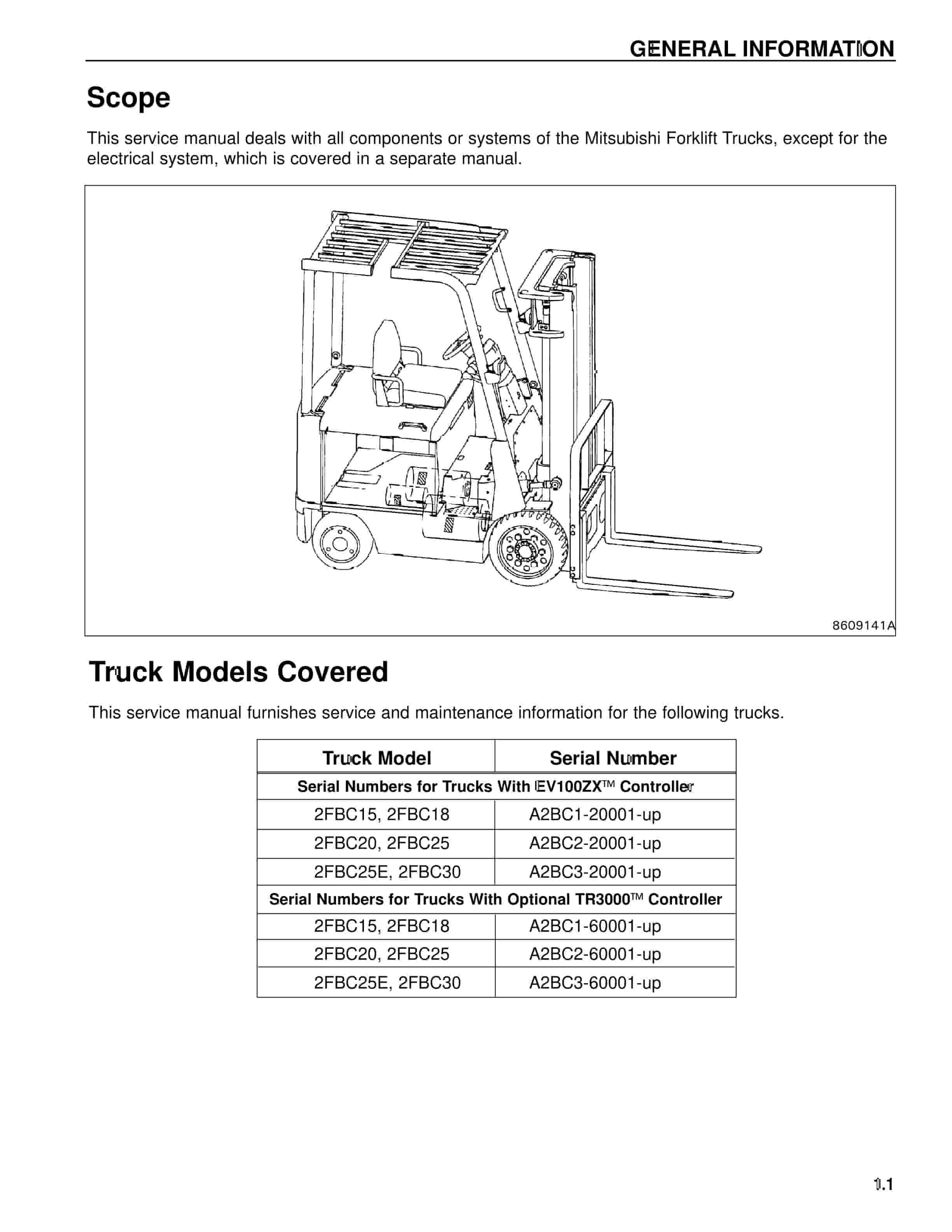
Mitsubishi 2FBC20 Forklift Service Manual
$50.00 Add to cart -
Mitsubishi 4G63, 4G64 Fuel System Supplement Service Manual 99729-75110
$50.00 Add to cart -
Mitsubishi 1204E Diesel Engine Disassembly and Assembly Service Manual 99799-56102
$50.00 Add to cart -
Mitsubishi PSI 4X LPG Engine Service Manual 99739-7C100
$50.00 Add to cart


