

Mitsubishi S4S Diesel Engine Service Manual 99616-87100
$30.00
- Type Of Manual: Service Manual
- Manual ID: 99616-87100
- Number of Pages: 190
- Size: 19.5MB
- Format: PDF
Product details
-
Model List:
- S4S Diesel Engine
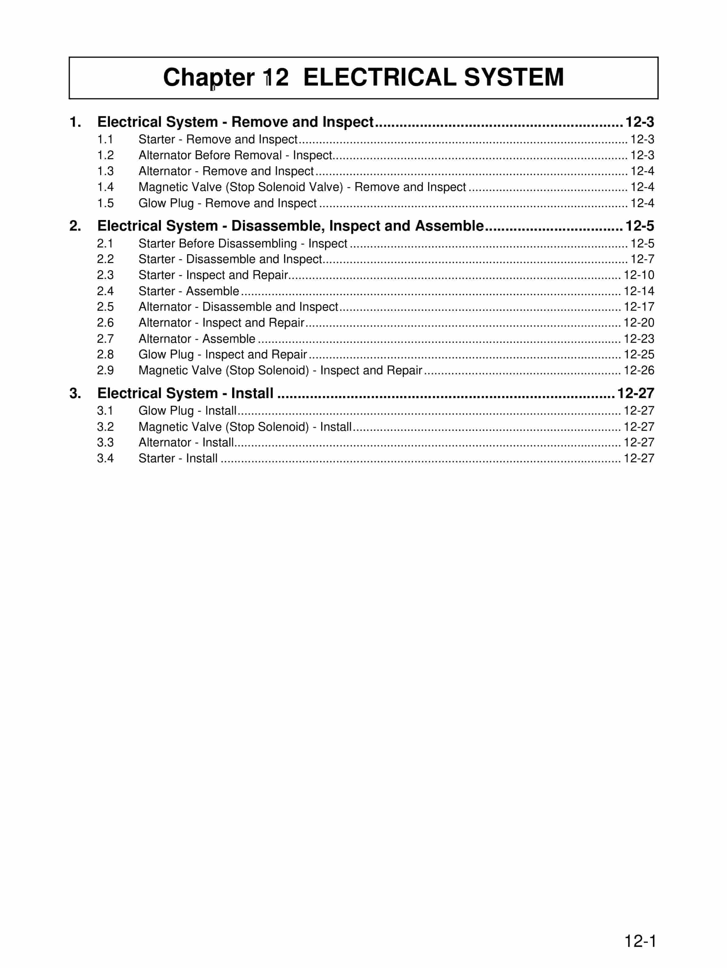
- 1. Foreword
- 1.1. HOW TO USE THIS MANUAL
- 1.1.1. Description format
- 1.1.2. Terms used in this manual
- 1.1.3. Abbreviations and Standards
- 1.1.4. Unit of Measurement
- 1.2. Safety Cautions
- 1.2.1. Fire and Explosion Precautions
- 1.2.2. Stay Away From Rotating and Moving Parts
- 1.2.3. Be Careful of Exhaust Gas Poisoning
- 1.2.4. Be Careful of Hearing Loss
- 1.2.5. Be Careful of Falling
- 1.2.6. Be Careful When Handling Fuel, Engine Oil or Coolant
- 1.2.7. Be Careful of Burns
- 1.2.8. Battery
- 1.2.9. When Abnormality Occurs
- 1.2.10. Other Cautions
- 1.2.11. Warning Labels
- 1.2.12. Points on Disassembling and Assembling
- 2. GENERAL CONTENTS
- 3. Chapter 1 GENERAL
- 3.1. External View
- 3.2. Outline of Systems
- 3.2.1. Outline of Fuel System
- 3.2.2. Outline of Lubrication System
- 3.2.3. Outline of Cooling System
- 3.2.4. Outline of Inlet and Exhaust System
- 3.3. Engine Serial Number
- 3.4. Specifications
- 4. Chapter 2 SERVICE DATA
- 4.1. Maintenance Service Data
- 4.1.1. Maintenance Service Data of Engine General
- 4.1.2. Maintenance Service Data of Basic Engine
- 4.1.3. Maintenance Service Data of Fuel System
- 4.1.4. Maintenance Service Data of Lubrication System
- 4.1.5. Maintenance Service Data of Cooling System
- 4.1.6. Maintenance Service Data of Inlet and Exhaust System
- 4.1.7. Maintenance Service Data of Electrical System
- 4.2. Tightening Torque Table
- 4.2.1. Tightening Torque Spec for Basic Engine
- 4.2.2. Tightening Torque Spec for Fuel System
- 4.2.3. Tightening Torque Spec for Lubrication System
- 4.2.4. Tightening Torque Spec for Cooling System
- 4.2.5. Tightening Torque Spec for Inlet and Exhaust System
- 4.2.6. Tightening Torque Spec for Electrical System
- 4.2.7. Tightening Torque for Standard Bolts
- 4.2.8. Tightening Torque for Standard Stud Bolts
- 5. Chapter 3 SERVICE TOOLS
- 5.1. Special Tools
- 6. Chapter 4 OVERHAUL INSTRUCTIONS
- 6.1. Determining Overhaul Timing
- 6.2. Compression Pressure – Measure
- 7. Chapter 5 DISASSEMBLY OF BASIC ENGINE
- 7.1. Cylinder Heads and Valve Mechanisms – Disassemble and Inspect
- 7.1.1. Inspection of Valve Clearance
- 7.1.2. Rocker Shaft Assembly – Remove
- 7.1.3. Cylinder Head Bolt – Remove
- 7.1.4. Cylinder Head Assembly – Remove
- 7.1.5. Measurement of Valve Sinkage
- 7.1.6. Valve and Valve Spring – Remove
- 7.2. Rear Mechanism – Disassemble and Inspect
- 7.2.1. Flywheel Face and Radial Runout – Measure
- 7.2.2. Flywheel – Remove
- 7.2.3. Oil Seal Case – Remove
- 7.2.4. Rear Plate – Remove
- 7.3. Front Mechanism – Disassemble and Inspect
- 7.3.1. Crankshaft Pulley – Remove
- 7.3.2. Timing Gear Case – Remove
- 7.3.3. Timing Gear Backlash – Measure
- 7.3.4. Idler Gear and Camshaft End Play – Measure
- 7.3.5. Fuel Injection Pump – Remove
- 7.3.6. Oil Pan – Remove
- 7.3.7. Oil Strainer – Remove
- 7.3.8. Oil Pump Gear – Remove
- 7.3.9. Idler Gear – Remove
- 7.3.10. PTO Drive Gear – Remove
- 7.3.11. Camshaft – Remove
- 7.3.12. Camshaft Gear – Replace
- 7.3.13. Front Plate – Remove
- 7.3.14. Oil Pump – Remove
- 7.4. Piston, Connecting Rod, Crankshaft and Crankcase – Disassemble and Inspect
- 7.4.1. Piston Protrusion – Measure
- 7.4.2. Carbon Deposits from the Upper Part of Cylinder – Remove
- 7.4.3. Connecting Rod End Play – Measure
- 7.4.4. Connecting Rod Cap – Remove
- 7.4.5. Piston – Remove
- 7.4.6. Piston Ring – Remove
- 7.4.7. Piston Pin and Piston – Remove
- 7.4.8. Crankshaft End Play – Measure
- 7.4.9. Main Bearing Cap – Remove
- 7.4.10. Crankshaft – Remove
- 7.4.11. Tappet – Remove
- 8. Chapter 6 INSPECTION AND REPAIR OF BASIC ENGINE
- 8.1. Cylinder Head and Valve Mechanism – Inspect and Repair
- 8.1.1. Clearance Between Rocker Bushing and Rocker Shaft – Measure
- 8.1.2. Valve Stem Outside Diameter and Valve Guide Inside Diameter – Measure
- 8.1.3. Valve Guide – Replace
- 8.1.4. Valve Face – Inspect
- 8.1.5. Valve Face – Reface
- 8.1.6. Valve Seat Ring – Reface
- 8.1.7. Valve Seat – Replace
- 8.1.8. Valve and Valve Seat Ring – Lap
- 8.1.9. Squareness and Free Length of Valve Spring – Measure
- 8.1.10. Push rod Runout – Measure
- 8.1.11. Distortion of Cylinder Head Bottom Surface – Measure
- 8.1.12. Combustion Jet – Replace
- 8.2. Rear Mechanism – Inspect and Repair
- 8.2.1. Flatness of Flywheel – Measure
- 8.2.2. Ring Gear – Inspect
- 8.2.3. Ring Gear – Replace
- 8.3. Front Mechanism – Inspect and Repair
- 8.3.1. Idler Bushing Inside Diameter and Idler Shaft Outside Diameter – Measure
- 8.3.2. Idler Shaft – Replace
- 8.3.3. Cam Lift of Cam Shaft Lobe – Measure
- 8.3.4. Camshaft Runout – Measure
- 8.3.5. Camshaft Journal Outside Diameter – Measure
- 8.3.6. Belt Groove Wear – Inspect
- 8.4. Piston and Connecting Rod – Inspect and Repair
- 8.4.1. Piston – Inspect Visually
- 8.4.2. Piston Weight
- 8.4.3. Piston Outside Diameter – Measure
- 8.4.4. Piston Ring Groove – Inspect
- 8.4.5. Piston Pin Bore Diameter and Piston Pin Outside Diameter – Measure
- 8.4.6. Standard for Piston Ring Replacement
- 8.4.7. Clearance Between Connecting Rod Bearing and Crankpin – Measure
- 8.4.8. Clearance Between Connecting Rod Bushing and Piston Pin – Measure
- 8.4.9. Connecting Rod Bushing – Replace
- 8.4.10. Connecting Rod Assembly Weight Rank
- 8.4.11. Connecting Rod Bearing – Inspect
- 8.4.12. Connecting Rod Bend and Twist – Inspect
- 8.5. Crankcase and Crankshaft – Inspect and Repair
- 8.5.1. Cylinder Inside Diameter – Measure
- 8.5.2. Crankcase Top Surface Distortion – Measure
- 8.5.3. Crankpin and Journal Outside Diameters – Measure
- 8.5.4. Width of Crankpin and Rearmost Crank Main Journal – Measure
- 8.5.5. Crankshaft – Grind
- 8.5.6. Crankshaft Runout – Measure
- 8.5.7. Crankshaft Gear – Inspect
- 8.5.8. Crankshaft Gear – Replace
- 8.5.9. Oil Seal Contact Surface – Inspect
- 8.5.10. Oil Seal Sleeve – Replace
- 8.5.11. Main Bearing – Inspect
- 8.5.12. Clearance Between Main Bearing and Crank Journal – Measure
- 8.5.13. Thrust Plate – Inspect
- 8.5.14. Tappet – Inspect
- 9. Chapter 7 ASSEMBLY OF BASIC ENGINE
- 9.1. Piston, Connecting rod, Crankshaft and Crankcase – Assemble
- 9.1.1. Crankcase – Turn Over (Upend)
- 9.1.2. Tappet – Install
- 9.1.3. Upper Main Bearing – Install
- 9.1.4. Rear Upper Thrust Plate – Install
- 9.1.5. Crankshaft – Install
- 9.1.6. Lower Main Bearing Shell and Lower Thrust Plate – Install
- 9.1.7. Main Bearing Cap – Install
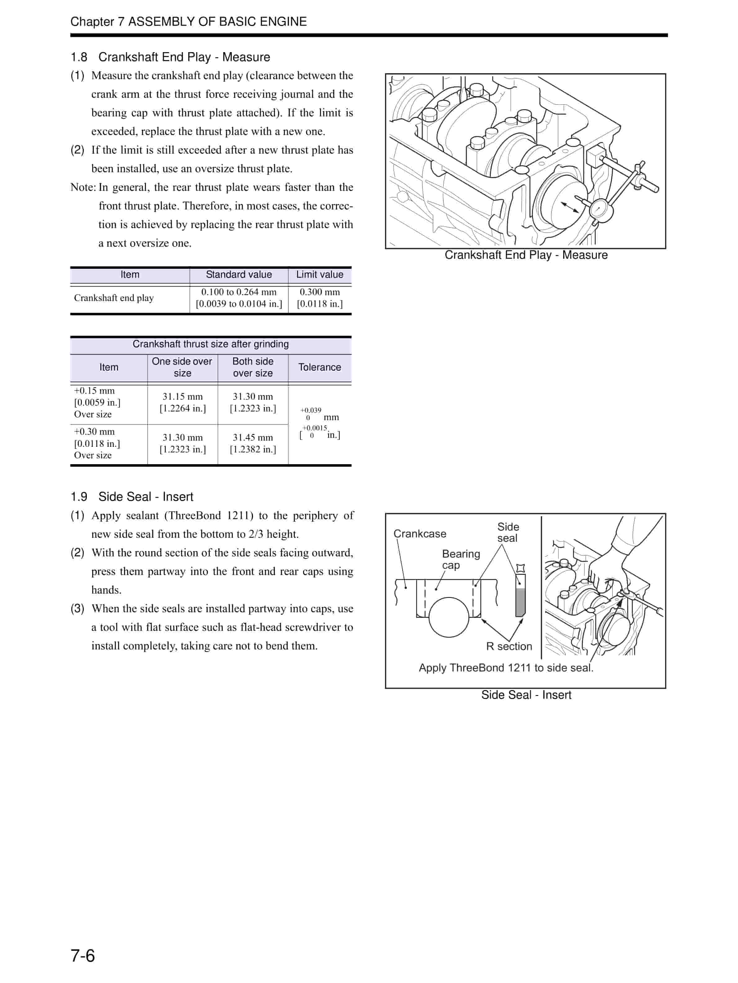
- 9.1.8. Crankshaft End Play – Measure
- 9.1.9. Side Seal – Insert
- 9.1.10. Piston and Connecting Rod – Assemble
- 9.1.11. Piston Ring – Install
- 9.1.12. Piston Installation – Prepare
- 9.1.13. Connecting rod bolt and Upper connecting rod bearing – Install
- 9.1.14. Piston – Install
- 9.1.15. Connecting Rod Cap – Install
- 9.1.16. Connecting Rod End Play – Measure
- 9.1.17. Piston Protrusion – Measure
- 9.2. Front Mechanism – Assemble
- 9.2.1. Oil Pump – Install
- 9.2.2. Front Plate – Install
- 9.2.3. Camshaft – Install
- 9.2.4. PTO Drive Gear – Install
- 9.2.5. Idler Gear – Install
- 9.2.6. Oil Pump Gear – Install
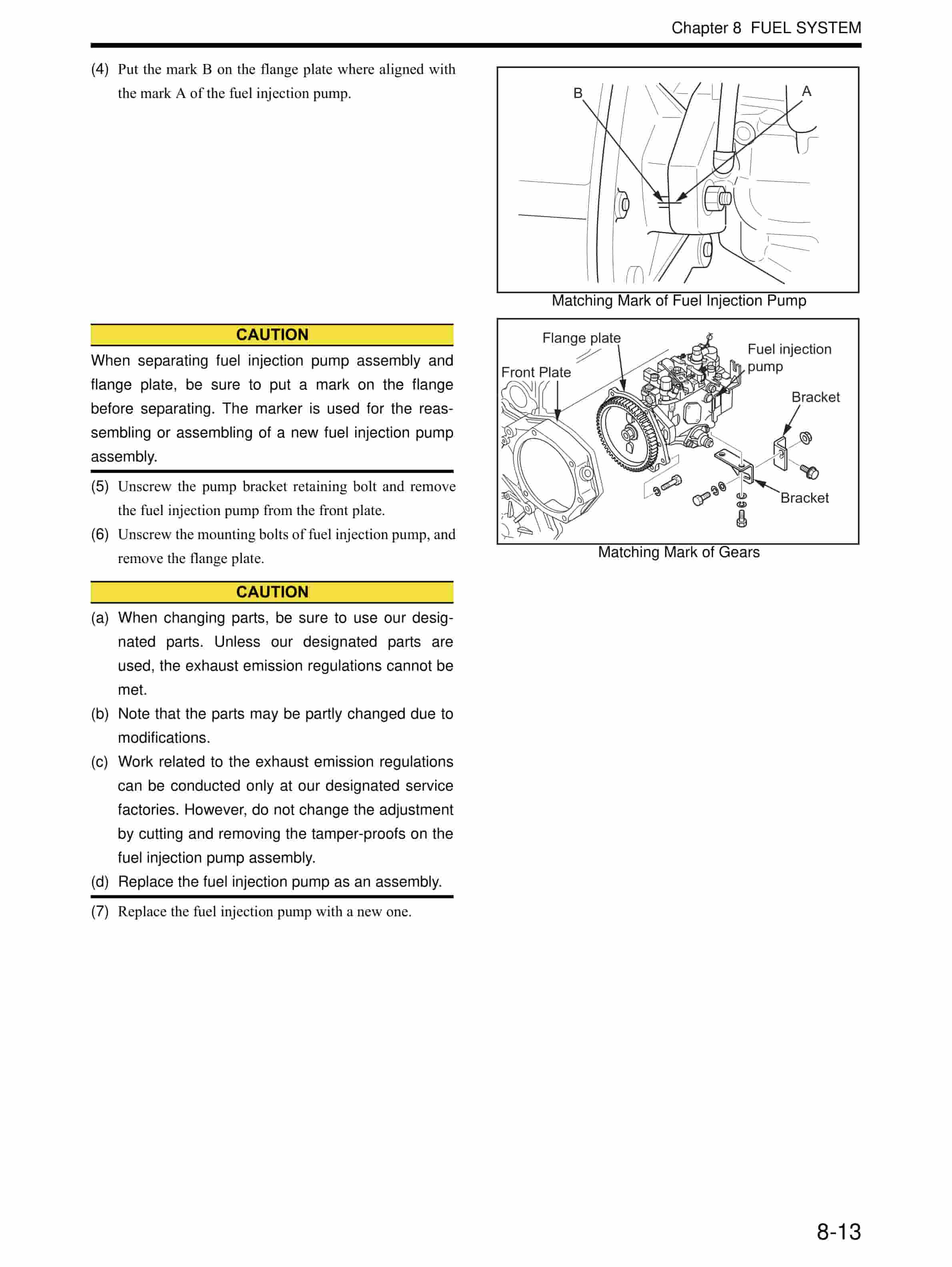
- 9.2.7. Fuel Injection Pump – Install
- 9.2.8. Timing Gear Backlash – Measure
- 9.2.9. Idler Gear End Play – Measure
- 9.2.10. Camshaft End Play – Measure
- 9.2.11. Front Oil Seal – Install
- 9.2.12. Timing Gear Case – Install
- 9.2.13. Oil Strainer – Install
- 9.2.14. Oil Pan – Install
- 9.2.15. Crankcase – Turn Over
- 9.2.16. Cover – Install
- 9.2.17. Crankshaft Pulley – Install
- 9.3. Rear Mechanism – Assemble
- 9.3.1. Rear Plate – Install
- 9.3.2. Oil Seal – Install
- 9.3.3. Flywheel – Install
- 9.3.4. Flywheel Face and Radial Runout – Measure
- 9.4. Cylinder Head and Valve Mechanism – Assemble
- 9.4.1. Cylinder Head – Assemble
- 9.4.2. Measurement of Valve Sinkage
- 9.4.3. Cylinder Head Gasket – Install
- 9.4.4. Cylinder Head Assembly – Install
- 9.4.5. Cylinder Head Bolt – Tighten
- 9.4.6. Push Rod – Insert
- 9.4.7. Rocker Shaft Assembly – Install
- 9.4.8. Valve Clearance – Check and Adjust
- 9.4.9. Rocker Cover – Install
- 10. Chapter 8 FUEL SYSTEM
- 10.1. Fuel System – Remove and Inspect
- 10.2. Fuel System – Disassemble, Inspect and Assemble
- 10.2.1. Fuel Filter (Paper Element) – Disassemble, Inspect and Assemble
- 10.2.2. Fuel Injection Nozzle – Disassemble and Inspect
- 10.2.3. Fuel Injection Nozzle – Inspect and Adjust
- 10.2.4. Fuel Injection Nozzle – Assemble
- 10.2.5. Gauze Filter of Distribute Type Fuel Injection Pump – Inspect and Clean
- 10.3. Fuel System – Install
- 10.3.1. Fuel Injection Timing – Check
- 11. Chapter 9 LUBRICATION SYSTEM
- 11.1. Lubrication System – Remove and Inspect
- 11.2. Lubrication System – Disassemble, Inspect and Assemble
- 11.2.1. Oil Pump – Disassemble and Inspect
- 11.2.2. Oil Pump – Inspect
- 11.2.3. Oil Pump – Assemble
- 11.2.4. Oil Filter – Inspect
- 11.2.5. Relief Valve – Inspect
- 11.3. Lubrication System – Install
- 12. Chapter 10 COOLING SYSTEM
- 12.1. Cooling System – Remove and Inspect
- 12.2. Cooling System – Disassemble, Inspect and Assemble
- 12.2.1. Thermostat – Disassemble and Inspect
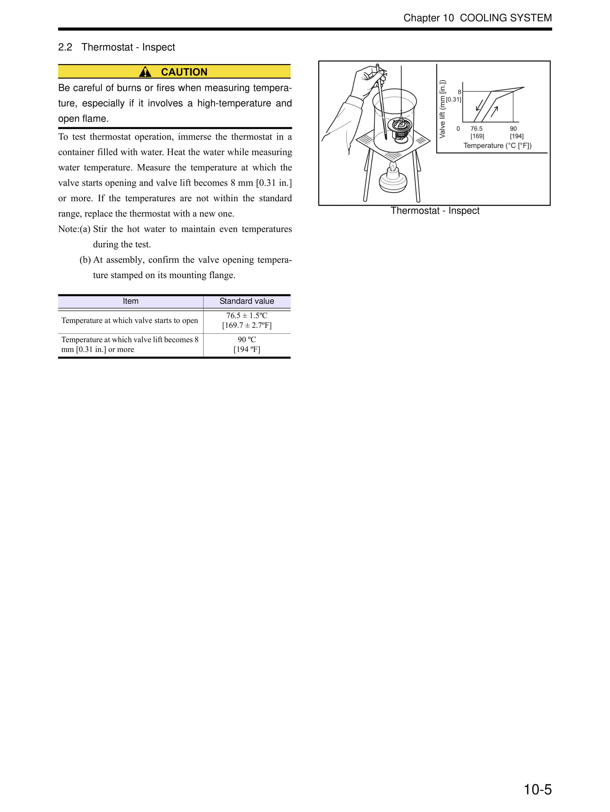
- 12.2.2. Thermostat – Inspect
- 12.2.3. Water pump – Disassemble and Inspect
- 12.3. Cooling System – Install
- 13. Chapter 11 INLET AND EXHAUST SYSTEMS
- 13.1. Inlet and Exhaust Systems – Remove and Inspect
- 13.2. Inlet and Exhaust Systems – Disassemble, Inspect and Assemble
- 13.2.1. Exhaust Manifold Distortion – Measure
- 13.3. Inlet and Exhaust Systems – Install
- 14. Chapter 12 ELECTRICAL SYSTEM
- 14.1. Electrical System – Remove and Inspect
- 14.1.1. Starter – Remove and Inspect
- 14.1.2. Alternator Before Removal – Inspect
- 14.1.3. Alternator – Remove and Inspect
- 14.1.4. Magnetic Valve (Stop Solenoid Valve) – Remove and Inspect
- 14.1.5. Glow Plug – Remove and Inspect
- 14.2. Electrical System – Disassemble, Inspect and Assemble
- 14.2.1. Starter Before Disassembling – Inspect
- 14.2.2. Starter – Disassemble and Inspect
- 14.2.3. Starter – Inspect and Repair
- 14.2.4. Starter – Assemble
- 14.2.5. Alternator – Disassemble and Inspect
- 14.2.6. Alternator – Inspect and Repair
- 14.2.7. Alternator – Assemble
- 14.2.8. Glow Plug – Inspect and Repair
- 14.2.9. Magnetic Valve (Stop Solenoid) – Inspect and Repair
- 14.3. Electrical System – Install
- 14.3.1. Glow Plug – Install
- 14.3.2. Magnetic Valve (Stop Solenoid) – Install
- 14.3.3. Alternator – Install
- 14.3.4. Starter – Install
- 15. Chapter 13 ADJUSTMENT AND OPERATION
- 15.1. Engine – Adjust
- 15.1.1. Valve Clearance – Check
- 15.1.2. Fuel System – Drain
- 15.1.3. Fuel System – Bleed Air
- 15.1.4. Belt and Belt Tension – Inspect and Adjust
- 15.2. Break-in Operation
- 15.2.1. Engine Start-up
- 15.2.2. Break-in Operation
- 15.3. Performance Test
- 15.3.1. Engine Equipment Condition
- 15.3.2. Test Items and Purposes
- 15.3.3. Other Inspections
- 15.3.4. Engine Output Adjustment
- 16. Back cover
- 17. Rear cover
Related products
-
Mitsubishi 1204E Diesel Engine Operation and Maintenance Manual Service Manual 99799-56105
$50.00 Add to cart -
Mitsubishi 4G63, 4G64 Gasoline Engine Service Manual 99729-14110
$50.00 Add to cart -
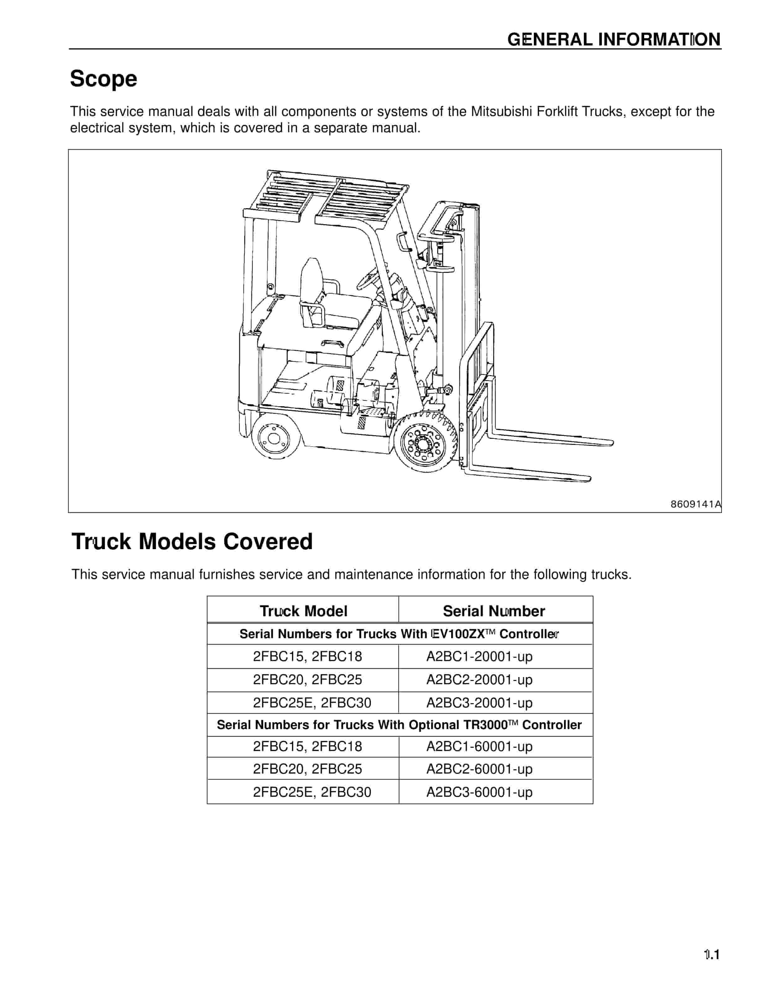
Mitsubishi 2FBC18 Forklift Service Manual
$50.00 Add to cart -
Mitsubishi PSI 4X LPG Engine Service Manual 99739-7C100
$50.00 Add to cart -
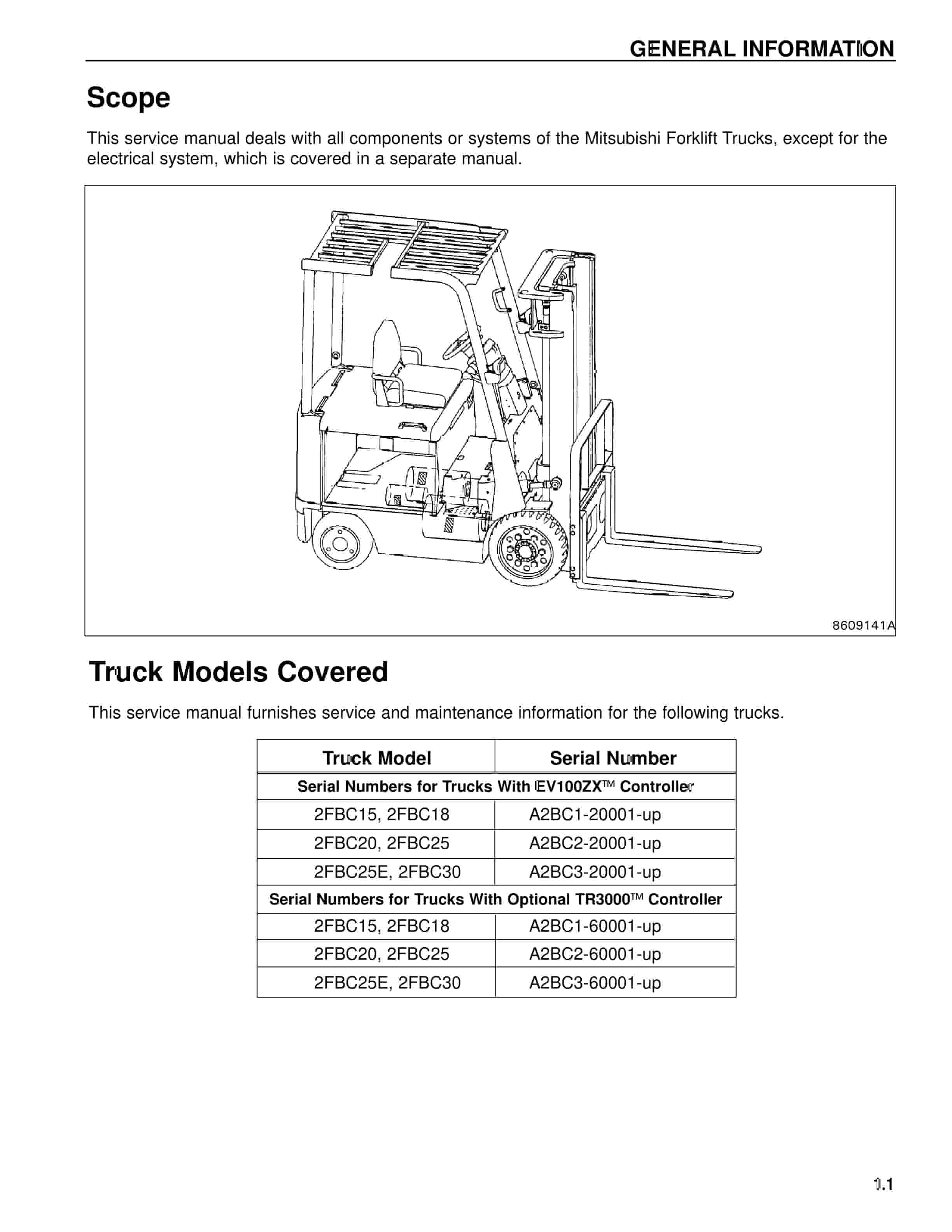
Mitsubishi 2FBC25 Forklift Service Manual
$50.00 Add to cart


