

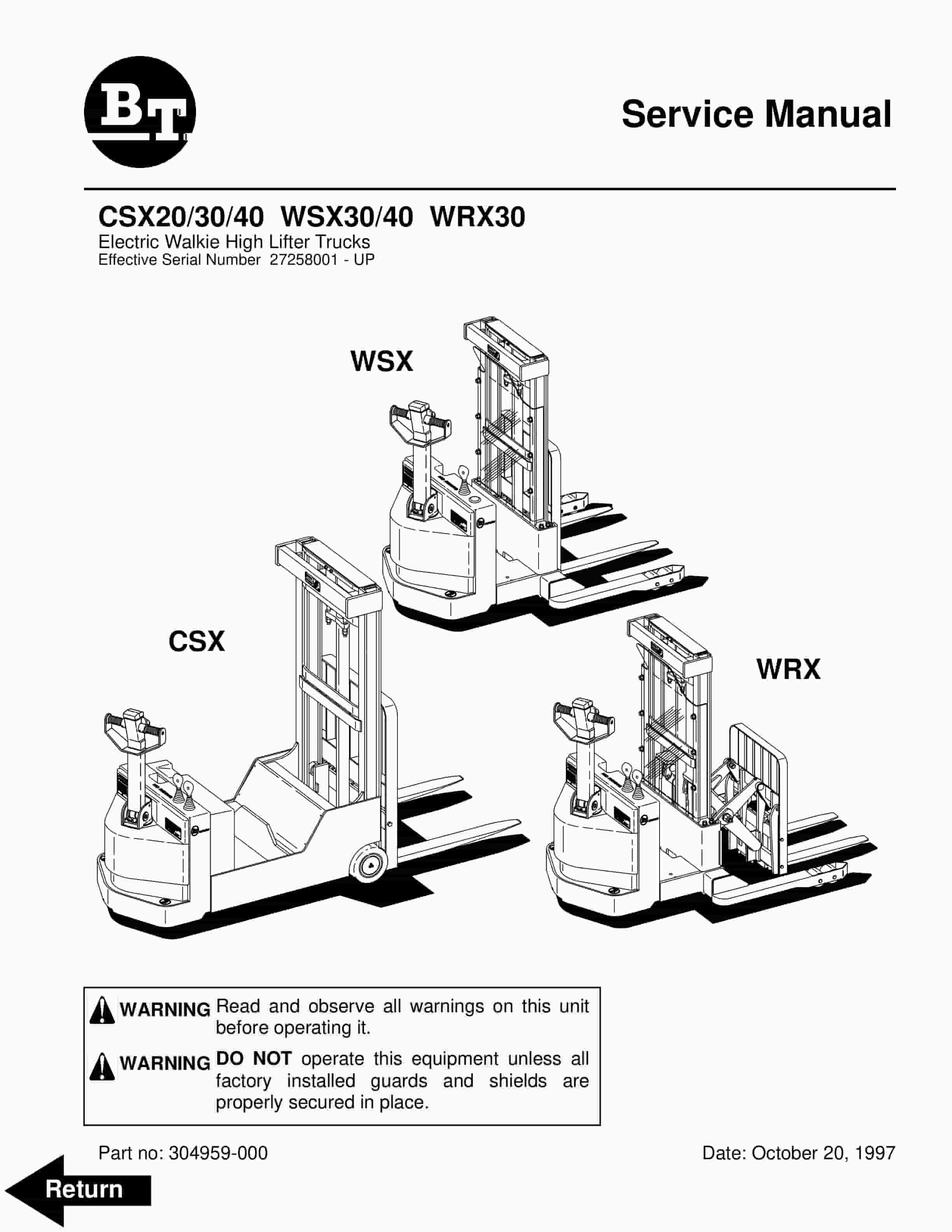
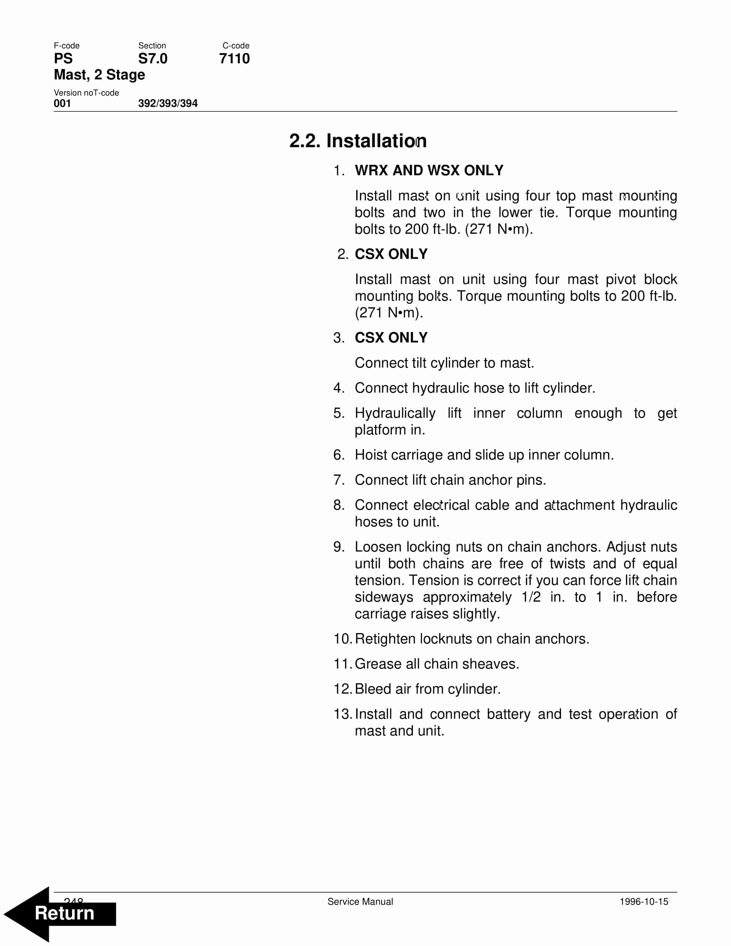
BT CSX20, CSX30, CSX40, WSX30, WSX40, WRX30 Electric Walkie High Lifter Truck Service Manual 304959-000
$30.00
- Type Of Manual: Service Manual
- Manual ID: 304959-000
- : Service Manual PDF
- Number of Pages: 312
- Size: 5.2MB
- Format: PDF
Product details
-
Model List:
- CSX20, CSX30, CSX40, WSX30, WSX40, WRX30 Electric Walkie High Lifter Truck
- 1. Front Cover
- 2. BT Standard Codes
- 3. Table of Contents
- 4. Warning Symbols
- 4.1. H 1. Warning Levels
- 5. Prohibitory Symbols
- 5.1. Ordinance Symbols
- 6. Introduction, Service Manual
- 7. Contents, Section M
- 7.1. Machine Information
- 8. General Product Information
- 8.1. Presentation of the Walkie Trucks.
- 8.1.1. H Heading3 First – 1.1. Intended Application of the Trucks
- 8.1.2. H Heading3 – 1.2. Forbidden Application of the Truck
- 8.1.3. H Heading3 – 1.3. Truck Data
- 8.1.4. H Heading3 – 1.4. CSX Dimensions
- 8.1.5. H Heading3 – 1.5. WSX Dimensions
- 8.1.6. H Heading3 – 1.6. WRX Dimensions
- 8.1.7. H Heading3 – 1.7. Data Plate
- 8.2. Main Components
- 9. Inch (SAE) and Metric Fasteners
- 9.1. Introduction
- 9.2. Nomenclature, Threads
- 9.3. Strength Identification
- 9.4. Conversion of Metric and English Units
- 10. Technical Service Data
- 11. Ordering Spare Parts
- 12. Contents, Section P
- 12.1. Planned Maintenance
- 13. Introduction, Maintenance
- 13.1. Safe Jacking Procedure
- 14. Service Schedule
- 14.1. Planned Maintenance Schedule
- 14.2. Planned Maintenance Procedures
- 14.2.1. H Heading3 First – 2.1. Services to be performed daily
- 14.2.2. Services to be performed monthly
- 14.2.3. Services to be performed annually
- 15. Lubrication Chart
- 16. Oil and Grease Specifications
- 16.1. Approved Oils and Grease
- 17. Contents, Section S
- 17.1. Service Instructions
- 18. Chassis, CSX
- 18.1. General
- 18.2. Main Components
- 19. Chassis, WRX and WSX
- 19.1. General
- 19.2. Support Arms
- 20. Drive Motor
- 20.1. General Information
- 20.2. Operating Conditions
- 20.3. Troubleshooting
- 21. Drive Motor 200 AMP
- 21.1. Component Repair
- 21.1.1. Disassembly
- 21.2. Inspection and Troubleshooting
- 21.2.1. Drive End Head
- 21.2.2. Commutator End Head
- 21.2.3. Bearings
- 21.2.4. Brush and Commutator
- 21.2.5. Armature
- 21.2.6. Frame and Field Assembly
- 21.2.7. Assembly
- 21.3. When Changing Brushes
- 22. Drive Motor 300 AMP
- 22.1. Component Repair
- 22.2. Inspection and Troubleshooting
- 22.2.1. Drive End Head
- 22.2.2. Commutator End Head
- 22.2.3. Bearings
- 22.2.4. Brush and Commutator
- 22.2.5. Armature
- 22.2.6. Frame and Field Assembly
- 22.2.7. Assembly
- 22.3. When changing brushes
- 23. Transmission
- 23.1. System description
- 23.2. Troubleshooting
- 23.3. Removal
- 23.4. Installation
- 24. Transmission Axle Seal
- 24.1. General Information
- 24.1.1. Removal
- 24.1.2. Installation
- 25. Transmission Disassembly / Assembly
- 25.1. Disassembly
- 25.2. Assembly
- 26. Parking Brake System
- 26.1. Brake Theory of Operation
- 26.2. Brake Adjustment
- 26.3. Brake Shoe Removal / Installation
- 27. Drive Wheel
- 27.1. Removal
- 27.2. Installation
- 28. Load Wheels, CSX
- 28.1. Removeal and Installation
- 29. Load Wheels, WRX/WSX
- 29.1. Removal and Installation
- 29.2. Stabilizing Caster
- 29.2.1. Maintenance and Adjustments
- 29.2.2. Caster Adjustment
- 29.2.3. Troubleshooting
- 29.2.4. Stabilizing Caster
- 30. Stabilizing Caster
- 30.1. Stabilizing Caster
- 30.1.1. Disassembly
- 30.1.2. Inspection
- 30.1.3. Assembly
- 31. Steering Arm / Handle
- 31.1. Control Handle Stem
- 31.1.1. Removal
- 31.1.2. Inspection
- 31.1.3. Installation
- 32. Steering Handle Head
- 32.1. Control Handle Head
- 32.1.1. Removal
- 32.1.2. Installation
- 32.2. Direction Control Switches
- 32.3. Horn, Raise, and Lower Switches
- 32.4. Potentiometer
- 33. Electrical System
- 33.1. Electrical Panel Components
- 33.2. List of Symbols
- 33.2.1. Circuit Diagram 1(5)
- 33.2.2. Circuit Diagram 2(5)
- 33.2.3. Circuit Diagram 3(5)
- 33.2.4. Circuit Diagram 4(5)
- 33.2.5. Circuit Diagram 5(5)
- 33.3. Description of Function
- 33.3.1. General
- 33.3.2. Adjustable Settings
- 33.3.3. References
- 33.3.4. Key Switch S17 in the ON Position
- 33.3.5. The Operating Arm in Drive Position, S10, Brake Switch Closed
- 33.3.6. Driving, Fork Direction
- 33.3.7. Driving, Steer Wheel Direction
- 33.3.8. Reversing/Motor Brake Fork Direction to Steer Wheel Direction
- 33.3.9. Reversing/Motor Brake Steer Wheel Direction to Fork Direction
- 33.3.10. Reverser switch
- 33.3.11. Lifting the Forks
- 33.3.12. Lowering the Forks
- 33.3.13. Horn
- 33.4. Options
- 33.4.1. Lifting the Forks (Manual Valve)
- 33.4.2. Tilting the Forks
- 33.4.3. Sideshifting the Forks
- 33.4.4. Extend/Retract the Forks
- 34. Amp Contactor
- 34.1. Maintenance
- 34.1.1. Removal/Replacement of Contact Tips
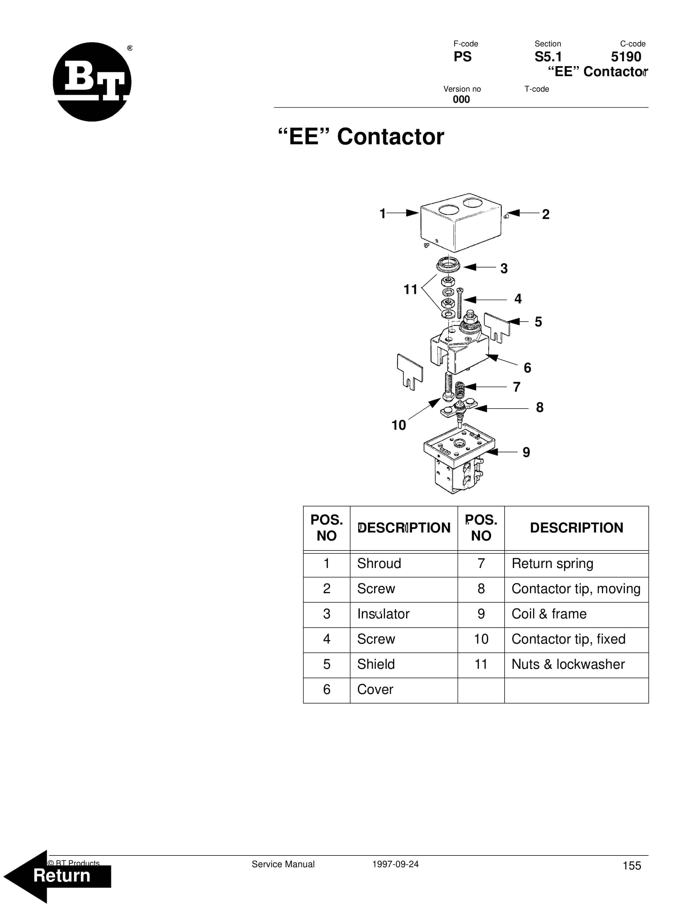
- 35. EE Contactor
- 35.1. Maintenance
- 35.1.1. Removal/Replacement of Contact Tips
- 36. Battery Controller / Hourmeter / Lift Interrupt
- 36.1. General Information
- 36.2. Electrical
- 36.2.1. Voltage
- 36.3. Battery Controller (BC)
- 36.3.1. General Information
- 36.3.2. Reset
- 36.3.3. Key Switch
- 36.3.4. Hourmeter
- 36.4. Troubleshooting
- 36.4.1. Battery Discharge Indicator (BDI)
- 36.4.2. Hourmeter
- 37. Transistor Controller
- 37.1. Motor Circuit
- 37.2. Control Circuit
- 37.3. Technical Specification
- 37.4. Adjustment of Controller
- 37.4.1. Connection of Handset
- 37.5. Maintenance
- 37.5.1. Safety
- 37.5.2. Cleaning
- 37.6. Diagnostics and Troubleshooting
- 37.6.1. Handset Diagnostics
- 37.6.2. Troubleshooting
- 37.6.3. Troubleshooting Chart Using the Handset
- 38. Electrical System Troubleshooting Chart Index
- 39. Electrical System Troubleshooting Charts
- 40. Handset Operation
- 40.1. Operating Modes
- 40.2. Revert to Previous Settings
- 40.3. Handset Self Test
- 40.4. LED Diagnostics
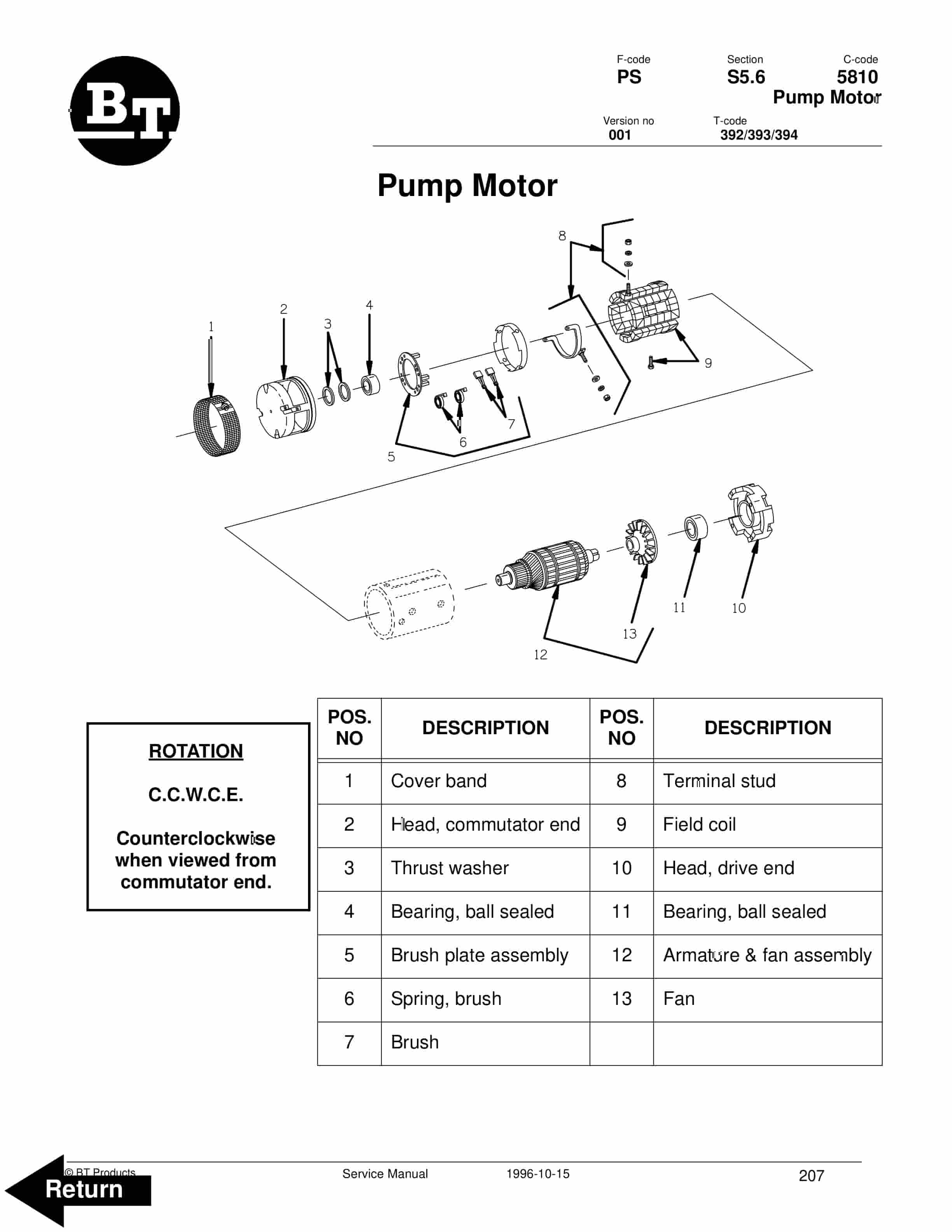
- 41. Pump Motor
- 41.1. Component Repair
- 41.1.1. Disassembly
- 41.2. Inspection and Troubleshooting
- 41.2.1. Drive End Head
- 41.2.2. Commutator End Head
- 41.2.3. Bearings
- 41.2.4. Brush and Commutator
- 41.2.5. Armature
- 41.2.6. Frame and Field Assembly
- 41.2.7. Assembly
- 41.3. When changing brushes
- 42. Hydraulic System
- 42.1. General
- 42.2. Description of Function
- 42.2.1. Hydraulic Schematic
- 42.2.2. CSX Hydraulic Schematic
- 42.2.3. WRX Hydraulic Schematic
- 42.2.4. WSX Hydraulic Schematic
- 42.3. Main Components
- 42.3.1. Description
- 42.4. Maintenance
- 42.5. Adjustments
- 42.6. Troubleshooting
- 42.6.1. Primary Malfunctions
- 42.7. Removal
- 42.8. Installation
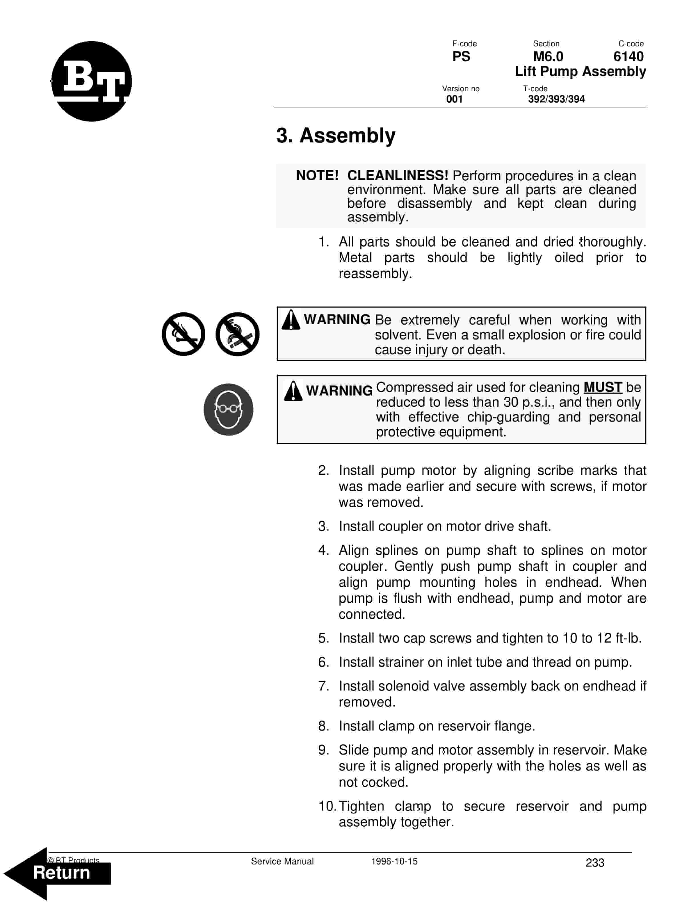
- 43. Lift Pump Assembly
- 43.1. Disassembly
- 43.2. Inspection
- 43.3. Assembly
- 44. Manual Spool Valve
- 44.1. Removal
- 44.2. Disassembly and Inspection
- 44.3. Assembly
- 45. Mast, 2 Stage
- 45.1. Shimming Mast on Truck.
- 45.1.1. Shimming the Carriage.
- 45.1.2. Shimming the Rails
- 45.2. Two Stage Mast
- 45.2.1. Removal
- 45.2.2. Installation
- 45.2.3. Disassembly
- 45.2.4. Assembly
- 46. Mast, 3 Stage
- 46.1. Shimming Mast on Truck.
- 46.1.1. Shimming the Carriage.
- 46.1.2. Shimming the Rails.
- 46.2. Three Stage Mast
- 46.2.1. Removal
- 46.2.2. Installation
- 46.2.3. Disassembly
- 46.2.4. Assembly
- 47. Sideshifter
- 47.1. Mounting Instructions
- 47.1.1. Installation
- 47.2. Operation and Maintenance
- 47.2.1. Lower Slides
- 47.2.2. Upper Slides
- 47.2.3. Cylinder
- 48. Reach, Single
- 48.1. Maintenance
- 48.2. Reach Repair
- 48.2.1. Disassembly
- 48.2.2. Assembly
- 49. Lift Cylinder, 2 Stage
- 49.1. Two Stage Full Freelift Mast Freelift Cylinder Repair
- 49.1.1. Removal
- 49.1.2. Disassembly
- 49.1.3. Assembly
- 49.1.4. Installation
- 49.2. Two Stage Full Freelift Mast Staging Cylinder Repair
- 49.2.1. Removal
- 49.2.2. Disassembly
- 49.2.3. Assembly
- 49.2.4. Installation
- 49.3. Two Stage Mast Lift Cylinder Repair
- 49.3.1. Removal
- 49.3.2. Disassembly
- 49.3.3. Assembly
- 49.3.4. Installation
- 50. Freelift Cylinder, 3 Stage
- 50.1. Freelift Cylinder Repair
- 50.1.1. Removal
- 50.1.2. Disassembly
- 50.1.3. Assembly
- 50.1.4. Installation
- 51. Tilt Cylinder, CSX
- 51.1. Removal
- 51.2. Disassembly
- 51.3. Inspection
- 51.4. Assembly
- 51.5. Installation
- 52. Tilt Cylinder, WRX
- 52.1. Removal
- 52.2. Disassembly
- 52.3. Inspection
- 52.4. Assembly
- 52.5. Installation
- 53. Reach Cylinder
- 53.1. Removal
- 53.2. Disassembly
- 53.3. Inspection
- 53.4. Assembly
- 53.5. Installation
- 54. Back Cover
Related products
-
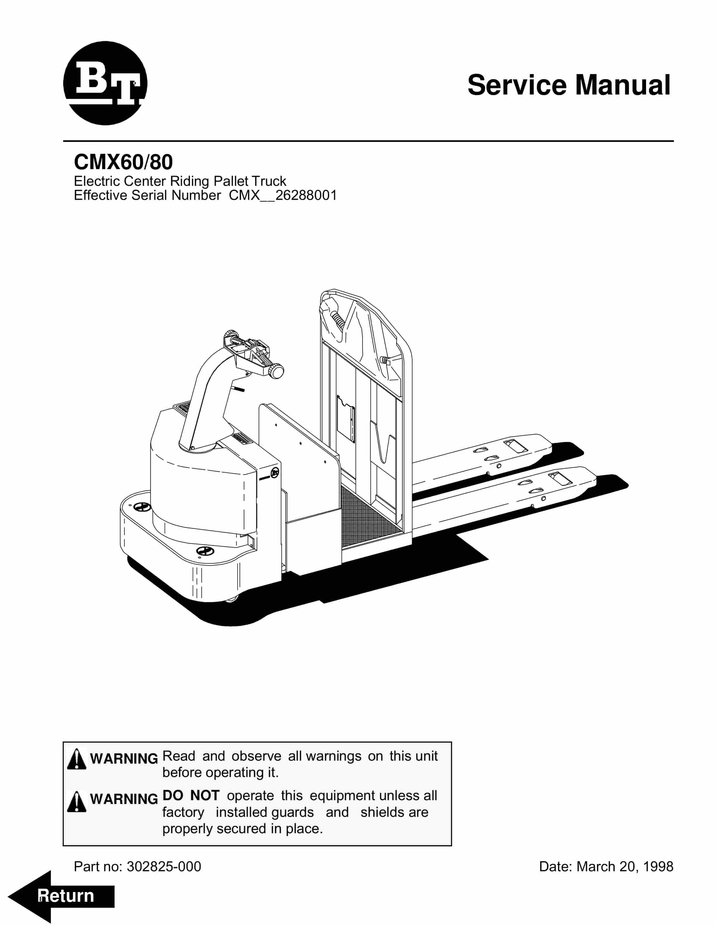
BT CMX60, CMX80 Electric Center Riding Pallet Truck Service Manual 302825-000
$30.00 Add to cart -
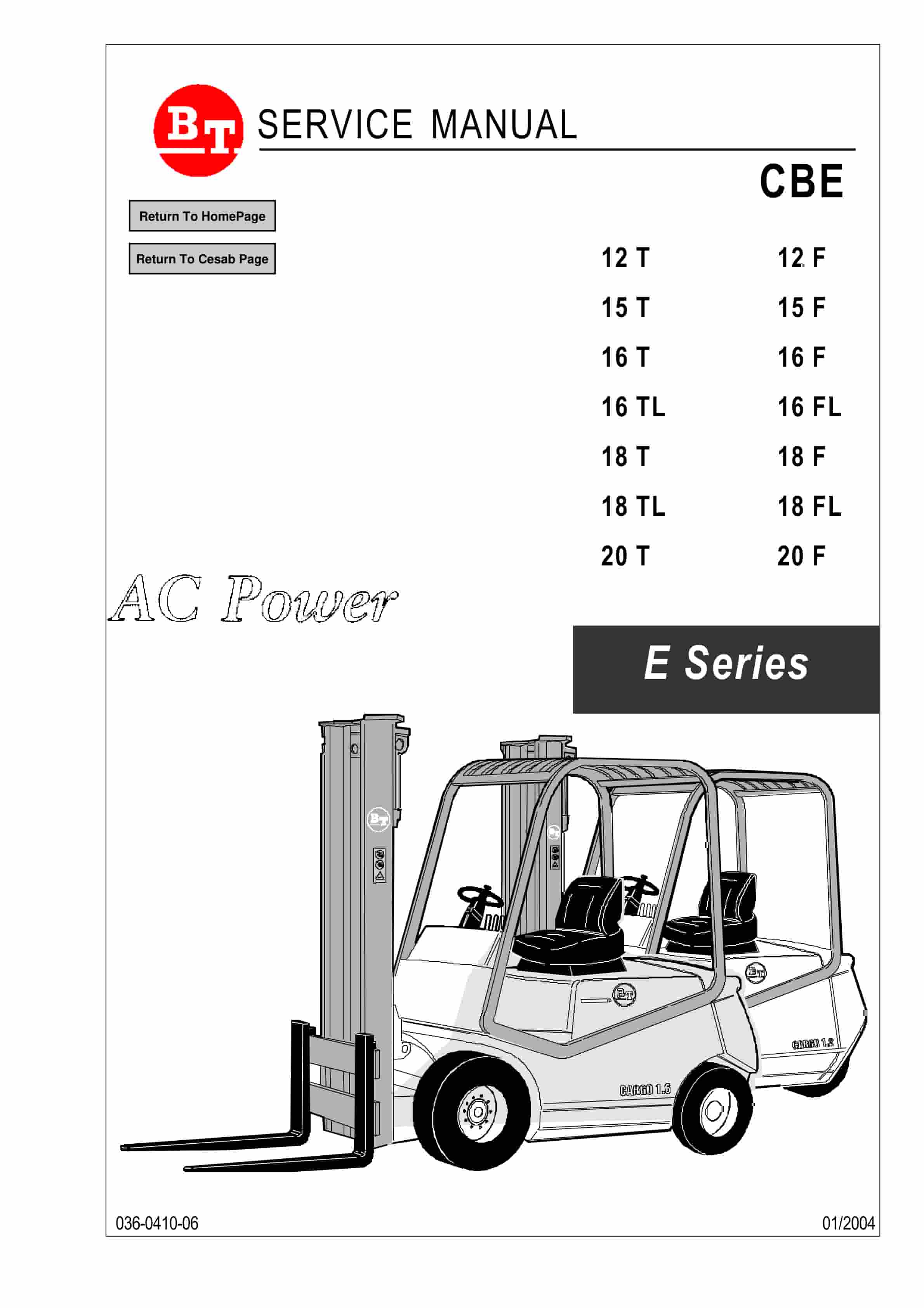
BT CBE 12T to CBE 20F Service Manual 036-0410-06
$30.00 Add to cart -
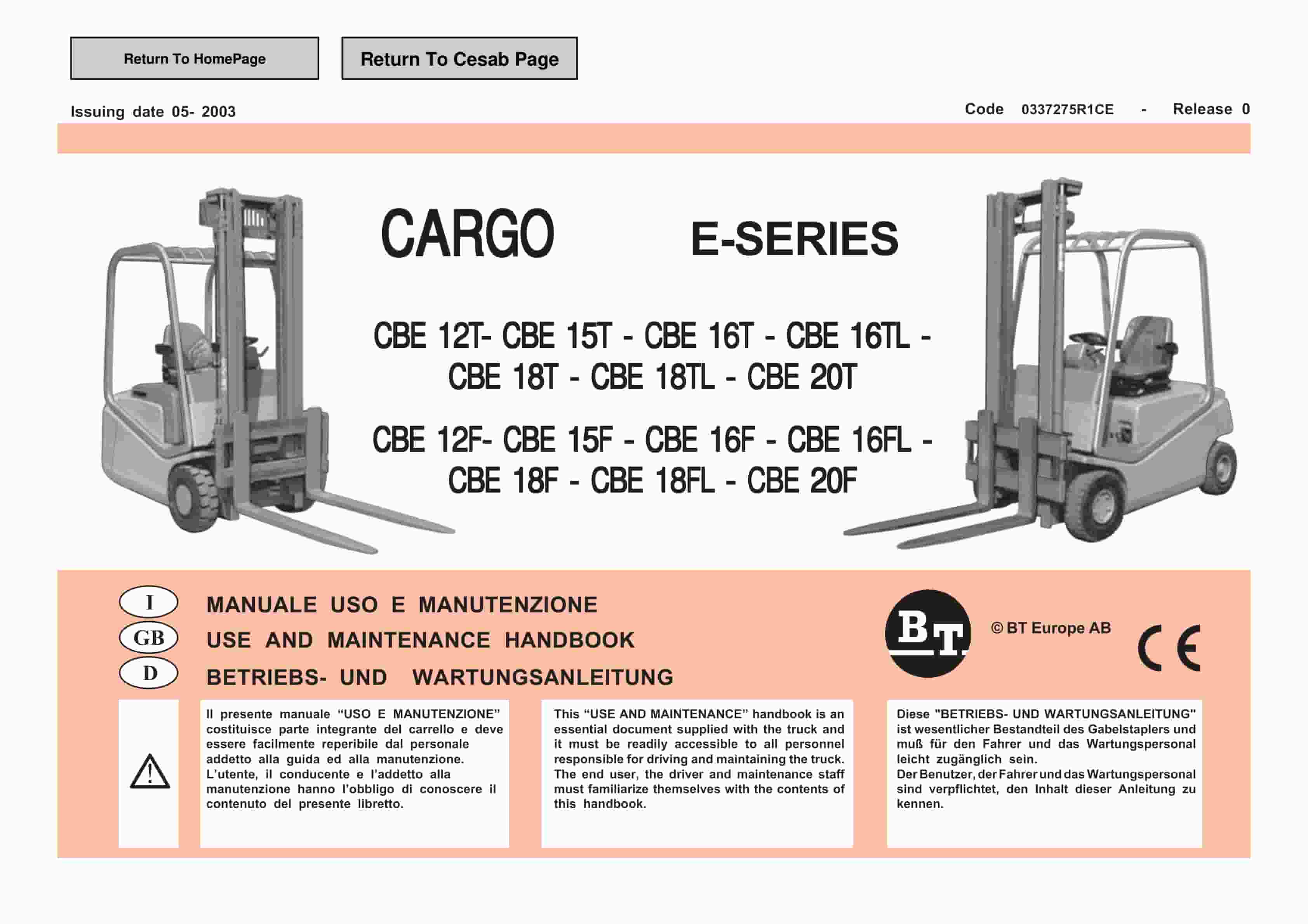
BT CARGE E-Series CBE 12T-20T, CBE 12F-20F Use And Maintenance Handbook 0337275R1CE
$30.00 Add to cart -
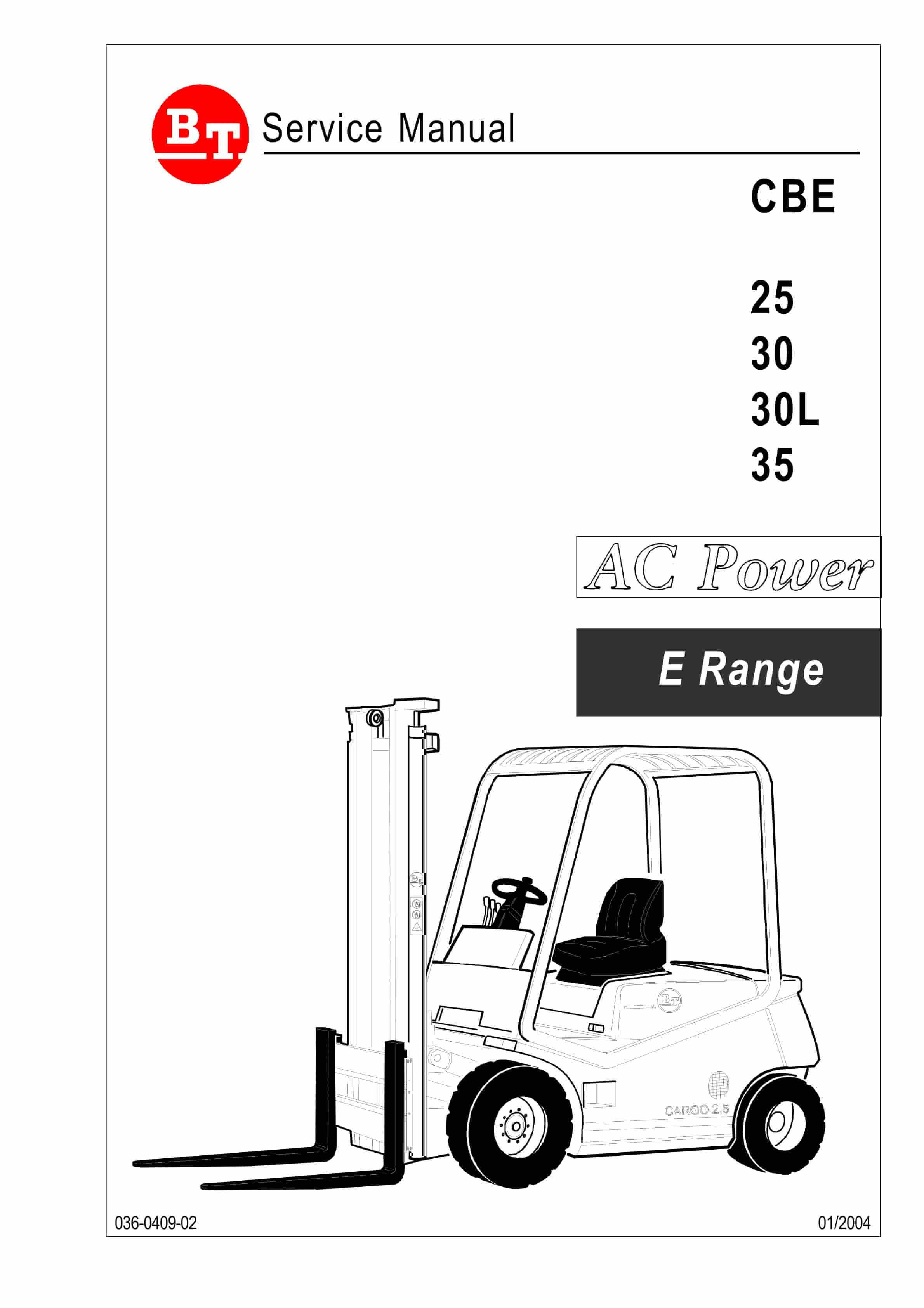
BT CBE 25, CBE 30, CBE 30L, CBE 35 Service Manual 036-0409-02
$30.00 Add to cart -
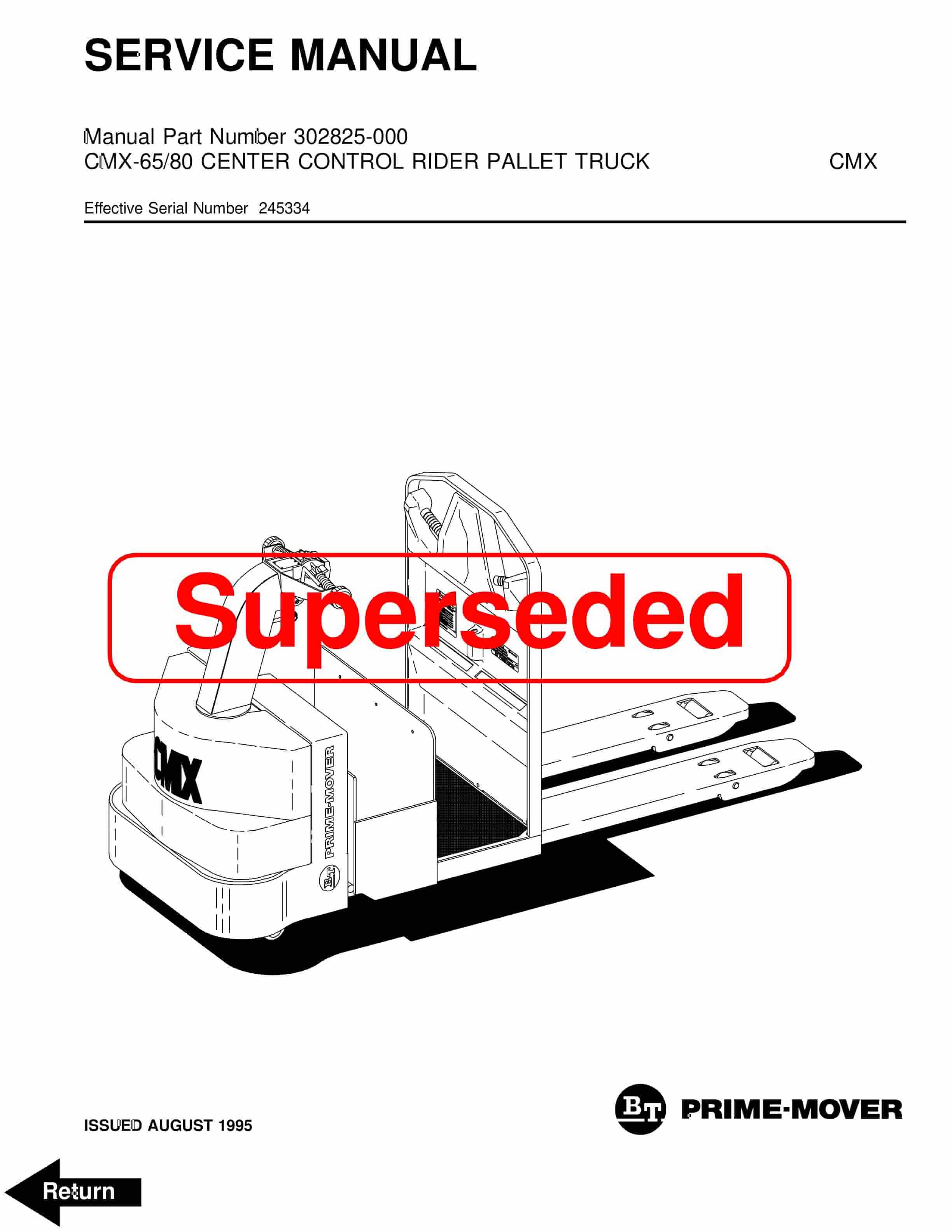
BT CMX-65, CMX-80 Center Control Riding Pallet Truck Service Manual 302825-000
$30.00 Add to cart


