


BT LPE200, LPE220, LPE250 Repair Manual 7572514
$30.00
- Type Of Manual: Repair Manual
- Manual ID: 7572514
- : Service Manual PDF
- Number of Pages: 528
- Size: 34.4MB
- Format: PDF
Category: BT Service Manual PDF
-
Model List:
- LPE200, LPE220, LPE250
- 1. Table of contents
- 2. General introduction
- 2.1. How to use this manual
- 2.2. Warning levels and symbols
- 2.3. Pictograms
- 3. General safety rules
- 3.1. Work safety
- 3.2. Electrical systems
- 3.3. Safe lifting
- 3.4. Truck modifications
- 4. Operation and connection sequences
- 4.1. Symbols on keypad and display
- 4.2. Battery is connected
- 4.3. Login via keypad
- 4.4. Login via ID key option
- 4.5. Tiller arm lowered for driving
- 4.6. Driving in fork direction
- 4.7. Driving in the drive wheel direction
- 4.8. Neutral position braking
- 4.9. Reverse braking
- 4.10. Mechanical braking
- 4.11. Emergency reversal
- 4.12. Fork lifting
- 4.13. Fork lowering
- 5. Parameters
- 5.1. General parameters
- 5.1.1. Show/change parameters
- 5.2. Operator parameters
- 5.2.1. Overview
- 5.2.2. Connection to logged-in operator
- 5.3. General service parameters
- 5.3.1. Overview
- 5.3.2. Description
- 5.4. Service parameters, travel functions
- 5.4.1. Overview
- 5.4.2. Description
- 5.5. Service parameters, hydraulic functions
- 5.5.1. Description
- 5.6. Factory parameters
- 5.6.1. Overview
- 5.6.2. Description
- 5.7. Calibration parameters
- 5.7.1. Overview
- 5.8. Calibration
- 5.8.1. Steering angle calibration 1
- 5.8.2. Hydraulic calibration 2
- 5.8.3. Calibration of weight measuring 3
- 5.8.4. Calibration of overload 4
- 5.8.5. Calibration of tilt angle 5
- 5.8.6. Calibration of weight measuring 6
- 6. Installation and commissioning
- 6.1. Transporting the truck
- 6.2. Transporting the mast
- 6.3. Lifting the truck
- 6.3.1. Lift using an eye bolt
- 6.3.2. Lift using a jack
- 6.4. Battery installation
- 6.4.1. Safety when handling batteries
- 6.4.2. Installing the battery
- 6.5. Managing PIN codes
- 6.5.1. General
- 6.5.2. PIN code for resetting after a collision
- 6.5.3. Programming PIN codes
- 6.5.4. PIN code defaults
- 6.6. Setting parameters
- 6.6.1. Setting collision sensor parameters (option)
- 6.6.2. Setting battery parameters
- 6.7. Function check
- 7. Maintenance
- 7.1. Introduction
- 7.2. Maintenance instructions
- 7.2.1. Cleaning and washing
- 7.2.2. High-pressure washers
- 7.2.3. Degreasing agents
- 7.2.4. Cleaning the exterior
- 7.2.5. Cleaning the chain
- 7.2.6. Cleaning the motor compartment
- 7.2.7. Electric components
- 7.3. Oil and grease specification
- 7.4. Symbols
- 7.5. Periodic maintenance
- 8. Troubleshooting
- 8.1. Towing a defective truck
- 8.1.1. Tow using a tow truck and tow wagon
- 8.2. Auxiliary functions
- 8.2.1. Emergency driving mode
- 8.3. Error code history
- 8.3.1. Extended error log
- 8.4. Error code system
- 8.5. Error codes
- 8.6. Service information
- 8.7. Digital input/output status
- 8.7.1. Test mode 9
- 8.7.2. Test mode 12 Expansion unit SEU (option).
- 8.8. Built-in test function for the tiller arm
- 8.8.1. Display test
- 8.8.2. Speed control
- 8.8.3. Safety reversing
- 8.8.4. Controls for lifting/lowering
- 8.8.5. Sensilift
- 8.8.6. Keypad
- 9. Chassis C0000
- 9.1. Overview
- 9.2. Hoods, covers C0340
- 9.2.1. Overview
- 9.2.2. Replacing the service cover
- 9.2.3. Replacing the side cover
- 9.2.4. Replacing the cover (without gate)
- 9.2.5. Replacing the gate cover
- 9.2.6. Replacing the emblem cover
- 9.2.7. Replacing the upper cover
- 9.2.8. Replacing the steering adapter cover
- 9.3. Fork frame C0380
- 9.3.1. Overview fork frame
- 9.3.2. Replacing the fork carriage
- 9.3.3. Checking the fork carriage
- 9.3.4. Replacing the torsion tube-linkage-wheel fork
- 9.3.5. Checking the torsion tube-linkage-wheel fork
- 9.4. Battery compartment parts C0390
- 9.4.1. Battery lock, fixed
- 9.4.2. Battery lock, quick
- 9.5. Drive unit suspension C0450
- 9.5.1. Overview
- 9.5.2. Overview,
- 9.5.3. Replacing the drive unit suspension
- 9.5.4. Relieving spring force using the special tool
- 9.5.5. Tensioning spring force using the special tool
- 9.5.6. Replacing the initial pressure spring
- 9.5.7. Replacing the PowerTrak spring
- 9.5.8. Replacing the PowerTrak cylinder
- 9.6. Platform including fixing points C0560
- 9.6.1. Overview, Standard and Cold store
- 9.6.2. Overview, platform with fixed side guard
- 9.6.3. Overview, platform
- 9.6.4. Replacing the platform
- 9.6.5. Replacing a platform with fixed side guard
- 9.6.6. Replacing the gas spring
- 9.6.7. Checking the gas spring
- 9.6.8. Replacing the spring
- 9.6.9. Adjusting platform suspension
- 9.6.10. Replacing the platform inductive position sensor
- 9.6.11. Checking the position sensor (B120)
- 9.6.12. Adjusting the presence sensor
- 9.7. Operator protection C0840
- 9.7.1. Gate
- 9.7.2. Replacing the gate
- 9.7.3. Replacing the gate damper
- 9.7.4. Replacing the pad
- 9.7.5. Replacing the gate bar
- 9.7.6. Checking the gate bar
- 9.7.7. Replacing the upper inductive position sensor
- 9.7.8. Checking the upper inductive position sensor B122
- 9.7.9. Replacing the lower inductive position sensor
- 9.7.10. Checking the lower inductive position sensor B121
- 9.7.11. Fixed side guard
- 9.7.12. Overview
- 9.7.13. Replacing the fixed side guard
- 9.7.14. Photo cells, fixed side guard
- 9.7.15. Back guard
- 9.7.16. Overview
- 9.7.17. Replacing the back guard
- 9.8. Signs, warnings, labels C0850
- 10. Motors C1000
- 10.1. Electric pump motor C1710
- 10.1.1. Overview
- 10.1.2. Replacing the pump motor
- 10.1.3. Replacing the carbon brushes
- 10.2. Steering motor C1730
- 10.2.1. Overview
- 10.2.2. Replacing the steering motor
- 10.3. Fans
- 10.3.1. Motor control fans
- 10.3.2. Overview
- 10.3.3. Replacing the motor control fans
- 10.4. Drive motor
- 10.4.1. Tightening torques Drive motor
- 10.5. , 2.5 kW
- 10.5.1. Overview
- 10.5.2. Connecting wiring harness 1.8 – 2.5 kW
- 10.5.3. Replacing the drive motor 1.8, 2.5 kW
- 10.6. KW
- 10.6.1. Overview
- 10.6.2. Connecting wiring harness, 2.8 kW
- 10.6.3. Replacing the motor 2.8 kW
- 10.6.4. Replacing the temperature sensor
- 10.6.5. Replacing the speed sensor
- 10.6.6. Replacing the speed sensor toothed wheel
- 10.6.7. Cleaning
- 11. Transmission/Drive gear C2000
- 11.1. Description
- 11.2. Gears
- 11.2.1. Small gear
- 11.2.2. Overview
- 11.2.3. Large gear
- 11.2.4. Overview
- 11.3. Replacing the drive gear
- 11.3.1. Removing the drive gear
- 11.3.2. Fitting the drive gear
- 11.4. Oil check and oil change, large gear
- 11.4.1. Draining oil
- 11.4.2. Checking/refilling oil
- 11.4.3. Replacing the steering bearing
- 11.5. Oil check and oil change, small gear
- 11.5.1. Draining oil
- 11.5.2. Checking/refilling oil
- 11.5.3. Replacing the steering bearing
- 11.5.4. Replacing studs
- 11.6. Replacing the wheel hub seal
- 11.6.1. Removing the seal
- 11.6.2. Fitting the seal
- 12. Brake system/Wheels C3000
- 12.1. Brake system C3100
- 12.1.1. Description
- 12.2. Parking brake – C3370
- 12.2.1. Overview
- 12.2.2. Checking the parking brake gap (adjustable brakes only)
- 12.2.3. Checking the parking brake gap (only for the small brake 21Nm in standard configuration)
- 12.2.4. Adjustment of the parking brake gap
- 12.2.5. Emergency parking brake release
- 12.2.6. Replacing the parking brake
- 12.2.7. Checking the parking brake
- 12.2.8. Replacing the friction disc
- 12.2.9. Replacing the brake hub
- 12.2.10. Cleaning the parking brake
- 12.3. Drive wheel
- 12.3.1. Overview
- 12.3.2. Replacing the drive wheel
- 12.4. Castor wheel
- 12.4.1. Replacing the castor wheel assembly
- 12.4.2. Checking the castor wheels
- 12.4.3. Replacing the castor wheel (single)
- 12.4.4. Replacing the castor wheel (twin wheel)
- 12.5. Fork wheels
- 12.5.1. Replacing single wheels
- 12.5.2. Replacing the bogie wheel
- 12.5.3. Replacing the wheel fork bushing
- 12.6. Wheel wear
- 13. Steering system C4000
- 13.1. Steering arm C4110
- 13.1.1. Overview
- 13.1.2. Replacing the handle to the tiller arm
- 13.1.3. Replacing the logic card
- 13.1.4. Checking the handle
- 13.1.5. Update the software
- 13.1.6. Replacing the signal button/switch
- 13.1.7. Replacement of lift/lower button
- 13.1.8. Replacing the button
- 13.1.9. Changing the position of the controls – support arm lift/ fork lift
- 13.1.10. Replacing the safety reversal switch
- 13.2. Steering arm C4110
- 13.2.1. Overview steering arm manual steering
- 13.2.2. Overview steering arm power steering
- 13.2.3. Overview steering arm ergo version
- 13.2.4. Replacing the steering yoke (manual and power steering)
- 13.2.5. Replacing the steering yoke (ergo version)
- 13.2.6. Replacing the steering yoke (manual and power steering)
- 13.2.7. Replacing the safety switch (manual and power steering)
- 13.2.8. Replacing the safety switch (ergo version)
- 13.2.9. Height adjustment of the steering adapter
- 13.2.10. Fixed steering adapter
- 13.2.11. Replacing the gas strut – height adjustment
- 13.2.12. Replacing the lock – height adjustment
- 13.2.13. Checking the lock – height adjustment
- 13.2.14. Replacing the steering adapter (fixed)
- 13.2.15. Replacing the steering adapter (adjustable)
- 13.2.16. Replacing the steering bearings – mechanical steering
- 13.2.17. Replacing the steering bearings – power steering
- 13.3. Mechanical steering
- 13.3.1. Overview
- 13.3.2. Replacing the steering angle sensor
- 13.4. Power steering
- 13.4.1. Safety
- 13.4.2. Overview
- 13.5. Steering angle sensor C4350
- 13.5.1. Replacing the steering angle sensor servo unit
- 13.5.2. Replacing the steering damper
- 13.5.3. Calibrating the steering damper/reference sensor
- 14. Electrical system C5000
- 14.1. General
- 14.1.1. Truck firmware applications
- 14.2. Menus
- 14.2.1. Menu navigation
- 14.2.2. Menu information
- 14.2.3. Show hour meter values
- 14.2.4. Show error codes
- 14.2.5. Show part numbers for software/hardware
- 14.2.6. Built-in test ICH
- 14.2.7. Show collisions
- 14.2.8. Show/change parameters
- 14.2.9. Emergency driving mode
- 14.2.10. Calibration
- 14.2.11. Show/change PIN code
- 14.2.12. Service mode
- 14.3. Battery C5110
- 14.3.1. Battery replacement
- 14.3.2. Charging the battery
- 14.4. Li-ion battery (Hoppecke)
- 14.4.1. Resetting/restarting the battery
- 14.5. Inspecting the battery
- 14.6. Electric panel
- 14.6.1. Overview
- 14.7. Transistor panel (ACT)
- 14.7.1. General
- 14.7.2. Replacing the transistor panel
- 14.7.3. Replacing the pump contactor
- 14.7.4. Replacing the main contactor
- 14.8. Horn C5160
- 14.8.1. Horn P4
- 14.9. Control system
- 14.9.1. Direction selector/speed regulator
- 14.9.2. Safety reversing
- 14.9.3. Battery indicator
- 14.9.4. Hour counter
- 14.9.5. Lifting and lowering control
- 14.9.6. Signal buttons
- 14.9.7. Option buttons
- 14.9.8. Display
- 14.9.9. Keypad/ID unit
- 14.9.10. Weighing system
- 14.9.11. Pressure equalization
- 14.9.12. Logic card (A5)
- 14.10. Work function harness/fuse
- 14.10.1. Fuse panel overview
- 14.11. Sending units and sensors C5800
- 14.11.1. Inductive sensors
- 14.11.2. Position sensor
- 14.11.3. Steering reference sensor
- 14.11.4. Pressure sensor
- 14.11.5. Pulse transducer
- 14.12. Safety sensor
- 14.12.1. Emergency switch off S21
- 14.12.2. Photocell
- 15. Hydraulic system C6000
- 15.1. General
- 15.2. Hydraulic hygiene
- 15.2.1. Washing
- 15.2.2. Packaging
- 15.2.3. Handling
- 15.2.4. Storage
- 15.2.5. Work procedures
- 15.3. Hydraulic system
- 15.3.1. Overview
- 15.3.2. Hydraulic unit
- 15.3.3. Tightening torques for hydraulic unit
- 15.3.4. Replacing the hydraulic unit
- 15.3.5. Tank
- 15.3.6. Changing oil
- 15.3.7. Replacing the tank
- 15.3.8. Valve unit
- 15.3.9. Hydraulic pump
- 15.3.10. Replacing the hydraulic pump
- 15.3.11. Replacing the return filter
- 15.3.12. Replacing the valve coil
- 15.3.13. Replacing the flow control valve
- 15.3.14. Pressure limitation
- 15.3.15. Replacing the pressure limiting valve
- 15.3.16. Adjusting pressure limitation
- 15.3.17. Replacing the pressure sensor
- 15.3.18. Lift cylinder
- 15.3.19. Replacing the lift cylinders
- 15.4. Hydraulic connections
- 15.4.1. Quick change connector
- 16. Mast C7000
- 17. Peripherals C8000
- 18. Options/Extra equipment C9000
- 18.1. Overview
- 18.2. Spider expansion unit
- 18.3. I_Site, previously T.W.I.S
- 18.4. DC/DC converter
- 18.5. Collision sensor
- 18.6. Integrated battery charger C5170
- 18.6.1. Overview
- 18.6.2. Description
- 18.6.3. Connecting the battery charger
- 18.7. E-bar
- 18.7.1. Overview
- 18.7.2. E-bar accessories
- 18.7.3. Fire extinguisher
- 19. Instructions for disposal
- 19.1. General
- 19.2. Marking of plastics
Rate this product
You may also like
BT Service Manual PDF
$30.00

BT Service Manual PDF
$30.00
BT Service Manual PDF
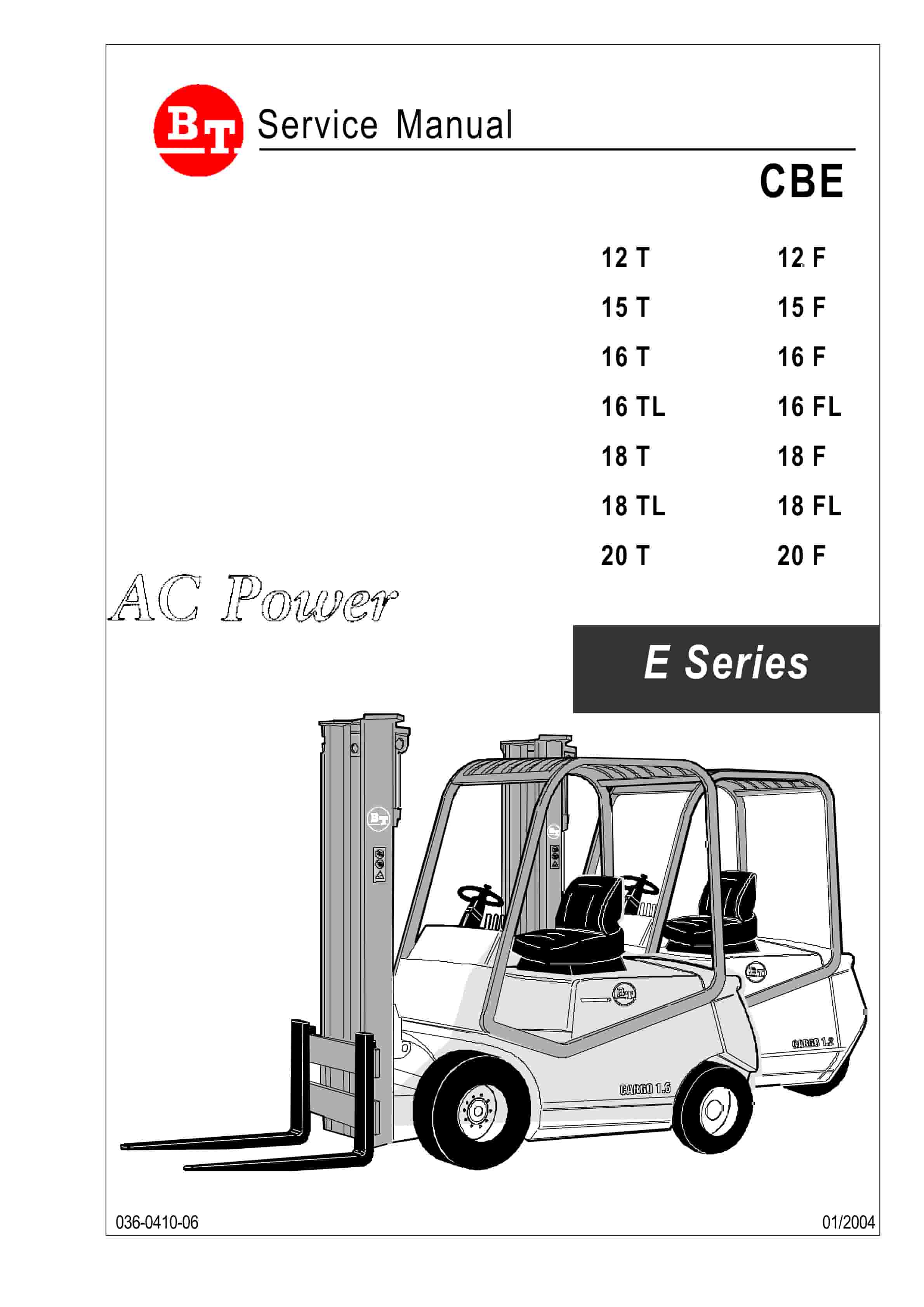
BT CARGE E-Series CBE 12T-20T, CBE 12F-20F Use And Maintenance Handbook 0337275R1CE
$30.00