


BT OE-30B OE Series Trucks Operating – Maintenance – Parts Manual 301069-000
$30.00
- Type Of Manual: Operating – Maintenance – Parts Manual
- Manual ID: 301069-000
- : Parts Manual PDF
- Number of Pages: 82
- Size: 4.1MB
- Format: PDF
Product details
-
Model List:
- OE-30B OE Series Trucks
- 1. Front Cover
- 2. Warranty
- 3. New Owners
- 4. Contents
- 5. Preliminary Service
- 6. Operation
- 7. Operating Rules and Instructions
- 8. Lubrication Chart
- 9. Maintenance Instructions
- 10. Service and Disassembly Instructions
- 11. Parts Ordering Instructions
- 12. Truck Specifications
- 13. Figure 1 Decal and Parts Assembly
- 14. Figure 2 Parts List and Service Reference Index
- 15. Figure 3 Shielding Assembly
- 16. Figure 4 Transmission Installation Assembly
- 17. Figure 5 Transmission Assembly 141
- 18. Figure 6 Motor Assembly
- 19. Figure 7 Motor Assembly
- 20. Figure 8 Brake Cylinder Assembly
- 21. Figure 9 Wiring Assembly Schematic
- 22. Figure 10 Electrical Schematic Symbols
- 23. Figure 11 Wiring Diagram Part 1
- 24. Figure 12 Wiring Diagram Part 2
- 25. Figure 13 Power Component Wiring
- 26. Figure 14 SCR and Contactor Panel Assembly
- 27. Figure 15 EV-1 SCR Control
- 28. Figure 16 Transformer Assembly
- 29. Figure 17 Rectifier Heat Sink Assembly
- 30. Figure 18 GE Contactor Assembly
- 31. Figure 19 Power Steering Contactor Assembly
- 32. Figure 20 GE Contactor Assembly
- 33. Figure 21 Warning Light Assembly
- 34. Figure 22 Connector Assembly
- 35. Figure 23 Hydraulic Assembly
- 36. Figure 24 Hydraulic Schematic
- 37. Figure 25 Hydraulic Schematic Symbols
- 38. Figure 26 Hydraulic Assembly Part 1
- 39. Figure 27 Pump and Motor Assembly
- 40. Figure 28 Motor Assembly
- 41. Figure 29 Torque Generator
- 42. Figure 30 Hydraulic Assembly Part 3
- 43. Figure 31 Hydraulic Assembly Part 4
- 44. Figure 32 Hydraulic Pump and Motor Assembly
- 45. Figure 33 Motor Assembly
- 46. Figure 34 Flow Control Valve
- 47. Figure 35 Hydraulic Assembly Part 5
- 48. Figure 36 Power Steering Control Assembly Part 1
- 49. Figure 37 Power Steering Control Assembly Part 2
- 50. Figure 38 2 Stage Mast Assembly
- 51. Figure 39 Lift Platform Assembly Part 1
- 52. Figure 40 Lift Platform Assembly Part 2
- 53. Figure 41 Handle Assembly
- 54. Figure 42 Master Control Switch Assembly
- 55. Figure 43 Pallet Clamp Assembly
- 56. Figure 44 2 Stage Inner Column Assembly
- 57. Figure 45 2 Stage Outer Mast Assembly
- 58. Figure 46 Staging Cylinder Assembly
- 59. Figure 47 3 Stage Mast Assembly
- 60. Figure 48 3 Stage Inner Column Assembly
- 61. Figure 49 3 Stage Freelift Cylinder Assembly
- 62. Figure 50 Freelift Cylinder Assembly
- 63. Figure 51 3 Stage Intermediate Column Assembly
- 64. Figure 52 3 Stage Outer Column Assembly
- 65. Figure 53 Frame Assembly
- 66. Service Guide
- 67. Back Cover
Related products
-
BT C4E 250NV Spare Parts Catalog 0350177R1-0
$30.00 Add to cart -
BT 602-TT, 608-TT, 609-TT, 610-TT, 612-TT, 620-TT Quality Parts 7504691
$30.00 Add to cart -
BT CARGO CBE 2.0F Spare Parts Catalog 0350144R1-0
$30.00 Add to cart -
BT C4E 200NL Spare Parts Catalog 0350175R1-0
$30.00 Add to cart -
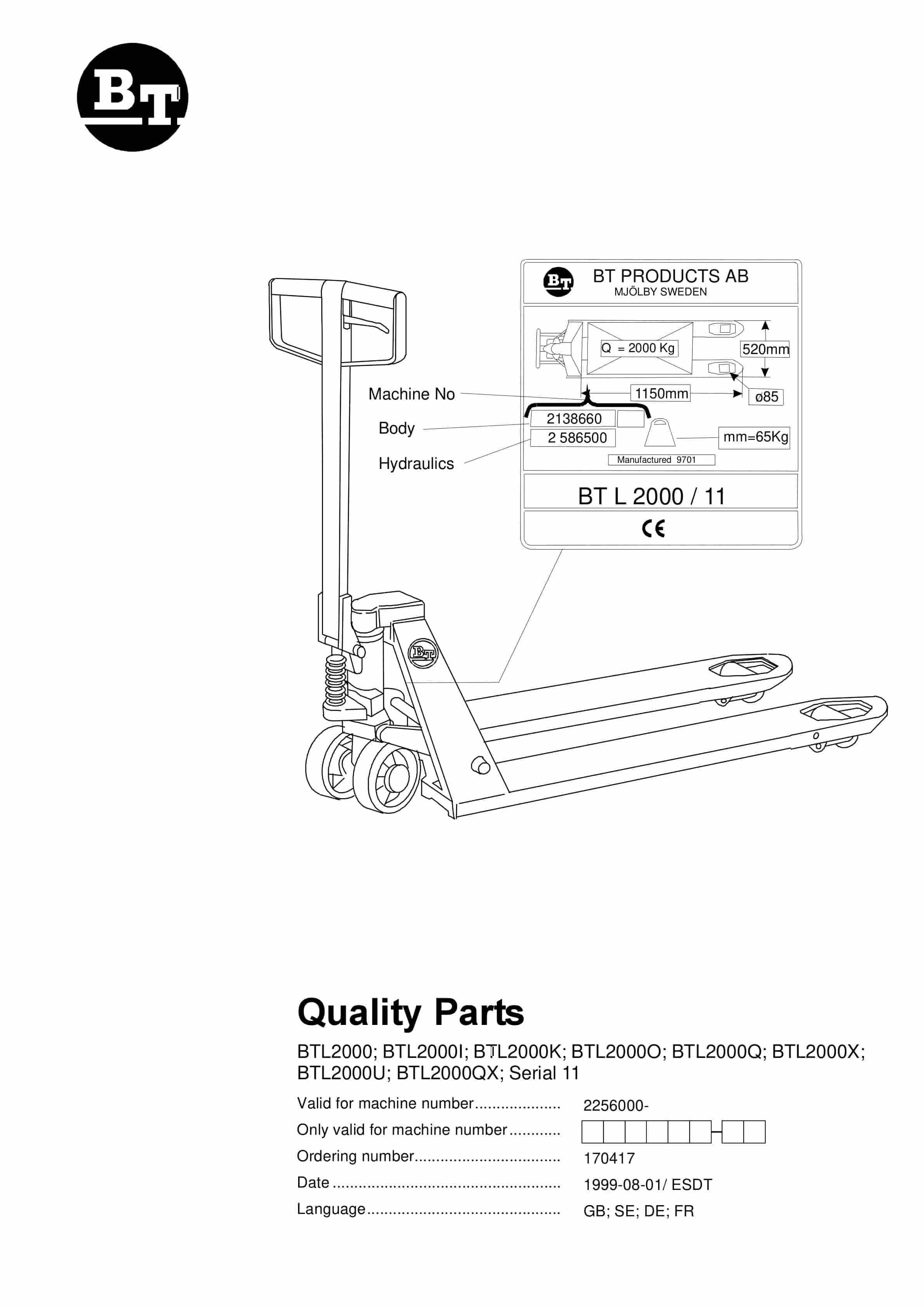
BT BTL2000, BTL2000I, BTL2000K, BTL2000O, BTL2000Q, BTL2000X, BTL2000U, BTL2000QX, Serial 11 Quality Parts 170417
$30.00 Add to cart