


BT OE-35 Electric Order Selector Parts Manual 300206-003
$30.00
- Type Of Manual: Parts Manual
- Manual ID: 300206-003
- : Parts Manual PDF
- Number of Pages: 176
- Size: 3.9MB
- Format: PDF
Product details
-
Model List:
- OE-35 Electric Order Selector
- 1. Front Cover
- 2. Parts Ordering Instructions
- 3. General Information
- 4. Alphabetical Index
- 5. Section 0.0
- 5.1. Figure 0.1 Decals and Parts Assembly
- 6. Section 1.0
- 6.1. Figure 1.1 Transmission Installation
- 6.2. Figure 1.2 Part 1 Transmission Assembly
- 6.3. Figure 1.3 Part 2 Transmission Assembly
- 7. Section 2.0
- 7.1. Figure 2.1 EV-100 LX Electrical Schematic
- 7.2. Figure 2.2 EV-100 LX Electrical Schematic Symbols
- 7.3. Figure 2.3 Wiring Diagram Part 1 Frame
- 7.4. Figure 2.4 Mast Cable and Related Parts
- 7.5. Figure 2.5 Wiring Diagram Part 2 Platform
- 7.6. Figure 2.6 EV-100 LX Power Component Wiring
- 7.7. Figure 2.7 EV-100 LX TX TTSCR Control Panel
- 7.8. Figure 2.8 EV-100 LX Contactor Panel Assembly Related Parts for E EE
- 7.9. Figure 2.9 EV-100 LX SCR Contactor Panel
- 7.10. Figure 2.10 EV-100 LX SCR Forward Rearward Contactor Assembly
- 7.11. Figure 2.11 EV-100 LX SCR 1A Contactor Assembly
- 7.12. Figure 2.12 EV-100 LX SCR Power Steering Contactor Assembly
- 7.13. Figure 2.13 Lift Pump Contactor Assembly
- 7.14. Figure 2.14 Emergency Disconnect Contactor Assembly
- 7.15. Figure 2.15 Power Connector Assembly
- 7.16. Figure 2.16 24 Volt Pump Motor Assembly
- 7.17. Figure 2.17 24 Volt Lift Pump Motor Assembly
- 7.18. Figure 2.18 36 Volt Pump Motor Assembly
- 7.19. Figure 2.19 24 Volt Drive Motor Assembly
- 7.20. Figure 2.20 36 Volt Drive Motor Assembly
- 7.21. Figure 2.21 24 Volt Power Steering Pump Motor Assembly
- 7.22. Figure 2.22 Power Steering Pump Motor Assembly
- 7.23. Figure 2.23 Warning Light Assembly
- 7.24. Figure 2.24 Wiring Assembly for Cold Storage
- 7.25. Figure 2.25 EV-100 LX TT Electrical Schematic
- 7.26. Figure 2.26 EV-100 LX TT Electrical Schematic Symbols
- 7.27. Figure 2.27 EV-100 LX Dash Display Installation
- 7.28. Figure 2.28 Battery Lift Interrupt Installation
- 8. Section 3.0
- 8.1. Figure 3.1 Hydraulic Schematic
- 8.2. Figure 3.2 Hydraulic Schematic Symbols
- 8.3. Figure 3.3 Steering and Brake Hose Assembly
- 8.4. Figure 3.4 Brake Cylinder Assembly
- 8.5. Figure 3.5 Steering Pump and Motor Assembly
- 8.6. Figure 3.6 Steering Pump Assembly
- 8.7. Figure 3.7 Lift Pump, Control Valve and Related Parts
- 8.8. Figure 3.8 Lift Pump and Motor Assembly
- 8.9. Figure 3.9 Lift Pump Assembly
- 8.10. Figure 3.10 Control Valve Assembly
- 8.11. Figure 3.11 Two Stage Mast Hydraulic Cylinder and Related Parts
- 8.12. Figure 3.12 Two Stage Staging Cylinder Assembly
- 8.13. Figure 3.13 Three Stage Clear View Mast Hydraulic Cylinders and Related Parts
- 8.14. Figure 3.14 Three Stage Clear View Mast Staging Cylinder Assembly
- 8.15. Figure 3.15 Three Stage Clear View Free Lift Cylinder Assembly
- 9. Section 4.0
- 9.1. Figure 4.1 Shielding Assembly
- 9.2. Figure 4.2 Frame and Load Wheel Installation
- 9.3. Figure 4.3 Platform Hand Rail Installation
- 9.4. Figure 4.4 Brake Foot Pedal and Chain Slack Switch Installation
- 9.5. Figure 4.5 Fork Mounting Installation
- 9.6. Figure 4.6 Pallet Clamp Installation
- 9.7. Figure 4.7 Handle Control Assembly
- 9.8. Figure 4.8 Lift Platform Shielding Assembly
- 9.9. Figure 4.9 Lift Platform Mast Rollers and Safety Belt
- 9.10. Figure 4.10 Mast Steering Control Part 1
- 9.11. Figure 4.11 Mast Steering Control Part 2
- 9.12. Figure 4.12 Frame Steering Control
- 9.13. Figure 4.13 Caster Assembly
- 10. Section 5.0
- 10.1. Figure 5.1 Two Stage Mast Installation
- 10.2. Figure 5.2 Two Stage Mast Outer Column Assembly
- 10.3. Figure 5.3 Two Stage Mast Inner Column Assembly
- 10.4. Figure 5.4 Three Stage Clear View Mast Outer Column Assembly
- 10.5. Figure 5.5 Three Stage Clear View Mast Intermediate Cylinder Assembly
- 10.6. Figure 5.6 Three Stage Clear View Mast Inner Column Assembly
- 10.7. Figure 5.7 Three Stage Clear View Mast Freelift Cylinder Installation
- 11. Section 6.0
- 11.1. Figure 6.1 Lights and Fan Assembly
- 12. Section 7.0
- 12.1. Figure 7.1 24 Volt NDC Electrical Schematic
- 12.2. Figure 7.2 24 Volt NDC Electrical Schematic Symbols
- 12.3. Figure 7.3 36 Volt NDC Electrical Schematic
- 12.4. Figure 7.4 36 Volt NDC Electrical Schematic Symbols
- 12.5. Figure 7.5 NDC Platform Wiring Harness and Related Parts
- 12.6. Figure 7.6 Mast Cable and Related Parts
- 12.7. Figure 7.7 NDC Main Frame Wiring Harness and Related Parts
- 12.8. Figure 7.8 Antenna and Related Parts Mounting Installation
- 12.9. Figure 7.9 Micro 70 and Related Parts Installation
- 12.10. Figure 7.10 Frame Steering Control and Servo-Motor Installation
- 12.11. Figure 7.11 Feedback Potentiometer and Tachometer Installation
- 12.12. Figure 7.12 36 Voltage Regulator Installation
- 13. Section 10.0
- 13.1. Figure 10.1 Special Tools and Lubrications
- 14. Numerical Index
- 15. Back Cover
Related products
-
BT BTL20EW, BTL20EWO, BTL30EW, BTL30EWO, L20BR, L20BRO, L30BR, L30BRO Quality Parts 177967
$30.00 Add to cart -
BT C4E 160NL Spare Parts Catalog 0350176R1-0
$30.00 Add to cart -
BT CARGO C3E 160 DC Spare Parts Catalog 0350191R1-0
$30.00 Add to cart -
BT 602-TT, 608-TT, 609-TT, 610-TT, 612-TT, 620-TT Quality Parts 7501655
$30.00 Add to cart -
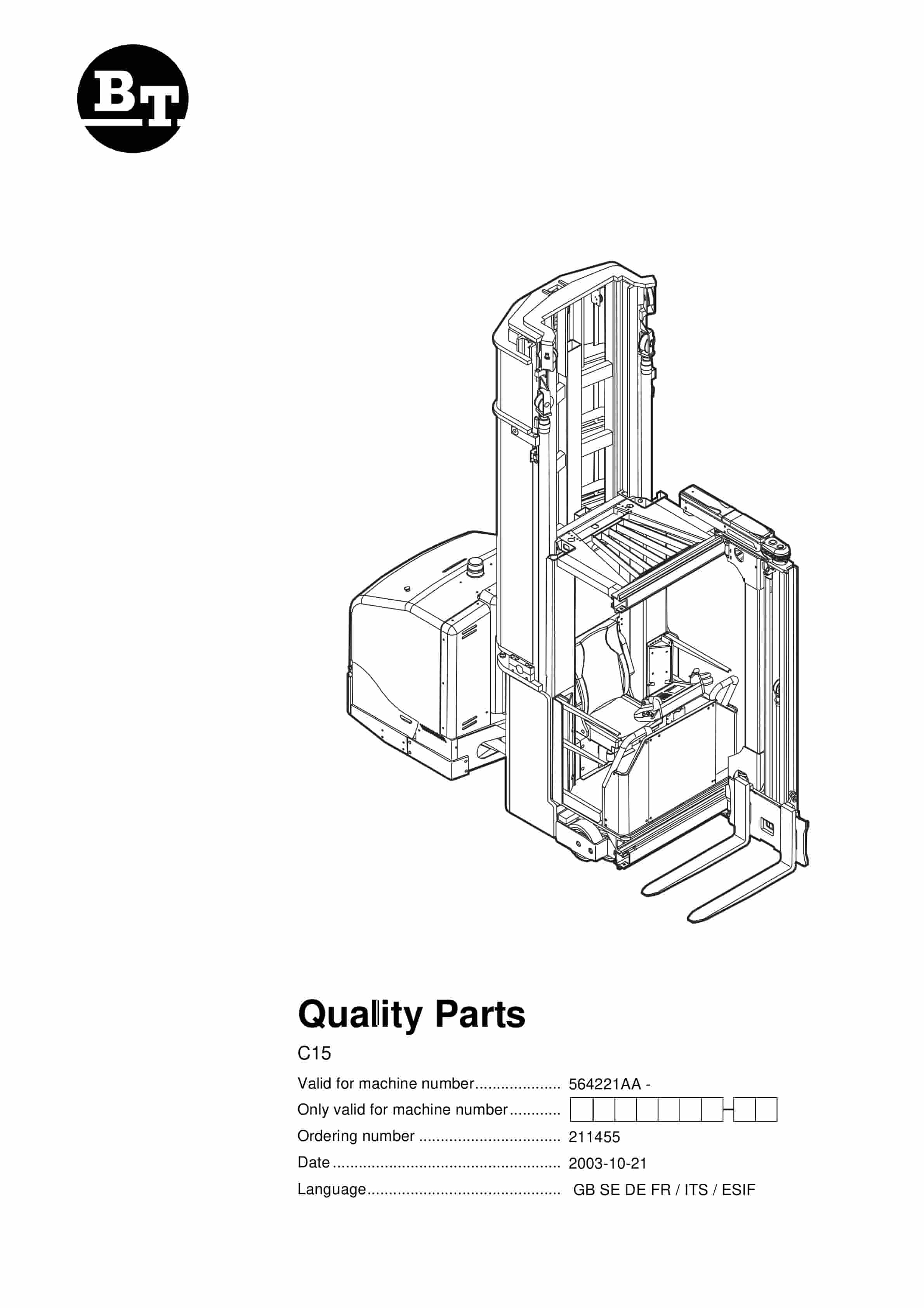
BT C15 564221AA Quality Parts 211455
$30.00 Add to cart