

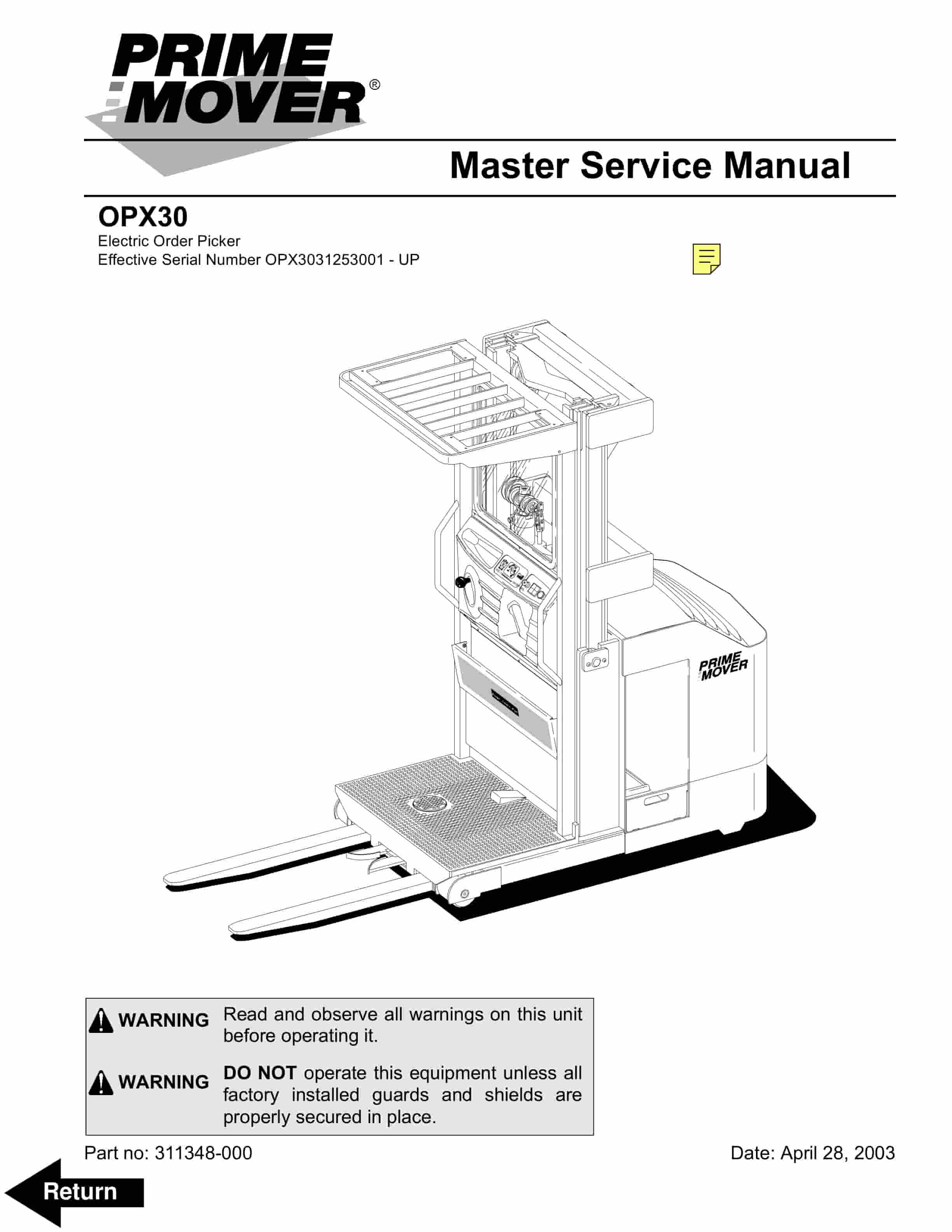
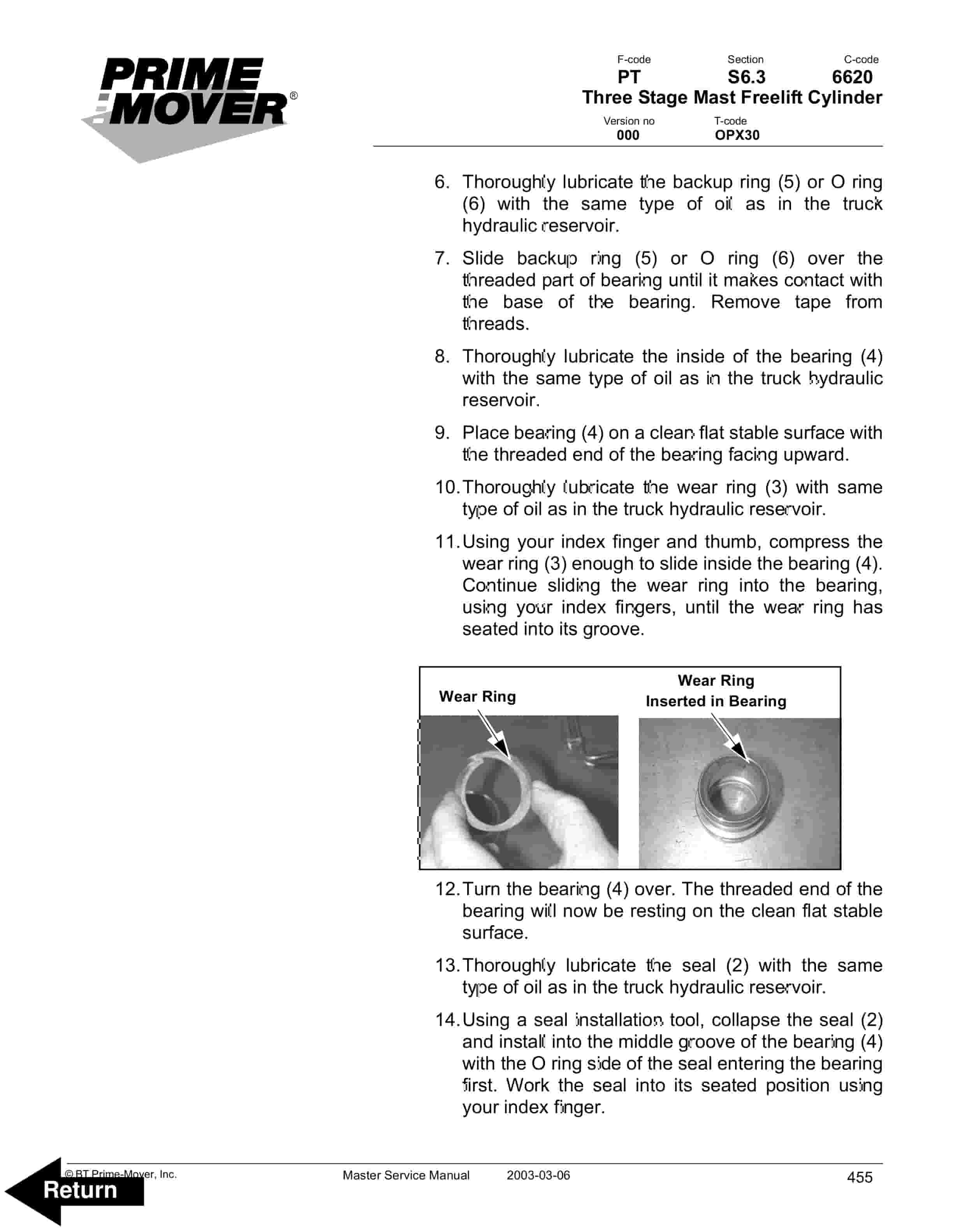
BT OPX30 Electric Order Picker Service Manual 311348-000
$30.00
- Type Of Manual: Service Manual
- Manual ID: 311348-000
- : Service Manual PDF
- Number of Pages: 570
- Size: 55.8MB
- Format: PDF
Product details
-
Model List:
- OPX30 Electric Order Picker
- 1. Front Cover
- 2. Standard Codes
- 3. Table of Contents
- 4. Warning Symbols
- 4.1. Warning Levels
- 5. Prohibitory Symbols
- 5.1. Ordinance Symbols
- 5.2. General Safety
- 6. Battery Safety
- 7. Static Discharge Precautions
- 8. Welding Safety
- 9. Introduction, Service Manual
- 10. Contents, Section M
- 10.1. Machine Information
- 11. General Product Information
- 11.1. Truck Presentation
- 11.1.1. Truck Side Views
- 11.1.2. Intended Truck Application
- 11.1.3. Prohibited Truck Application
- 11.1.4. Truck Data
- 11.1.5. Dimensions
- 11.1.6. Data Plate
- 11.2. Main Components
- 12. Inch (SAE) and Metric Fasteners
- 12.1. Introduction
- 12.2. Nomenclature, Threads
- 12.3. Strength Identification
- 12.4. Conversion of Metric and English Units
- 13. Technical Service Data
- 14. Ordering Spare Parts
- 15. Contents, Section P
- 15.1. Planned Maintenance
- 16. Introduction, Maintenance
- 16.1. Jacking Truck Off The Floor
- 16.1.1. Operator Platform
- 16.1.2. Truck Frame
- 16.1.3. Baseleg
- 16.2. Lubricants
- 16.2.1. Standard
- 16.2.2. Cold Storage
- 16.2.3. Freezer
- 17. Service Schedule
- 17.1. Planned Maintenance Schedule
- 17.2. Planned Maintenance Procedures
- 17.2.1. Services Performed Daily or Every 8 Operating Hours
- 17.2.2. Services Performed Monthly or Every 120 Operating Hours
- 17.2.3. Services Performed Semi-Annually or Every 720 Operating Hours
- 17.2.4. Services Performed Annually or Every 1440 Operating Hours
- 18. Lubrication Chart
- 19. Oil and Grease Specifications
- 19.1. Approved Oils and Grease
- 19.2. Grease Location Points
- 20. Contents, Section S
- 20.1. Service Instructions
- 21. Chassis
- 21.1. Theory of Operation
- 21.2. Maintenance
- 21.3. Troubleshooting
- 21.4. Repair and Rebuild
- 21.4.1. Front Cover
- 21.4.2. Front Panel
- 21.4.3. Left-hand Cover
- 21.4.4. Right-hand Cover
- 22. Operator Platform
- 22.1. Theory of Operation
- 22.2. Maintenance
- 22.3. Troubleshooting
- 22.4. Repair and Rebuild
- 22.4.1. Console Cover
- 22.4.2. Floor Mat
- 23. Battery Compartment
- 23.1. Theory of Operation
- 23.2. Maintenance
- 23.3. Troubleshooting
- 23.4. Repair and Rebuild
- 23.4.1. Battery Stop Plate
- 23.4.2. Battery
- 23.4.3. Battery Rollers
- 24. Operator Controls
- 24.1. Theory of Operation
- 24.2. Maintenance
- 24.3. Troubleshooting
- 24.3.1. Throttle Potentiometer Test
- 24.4. Repair and Rebuild
- 24.4.1. Multi-Function Control Handle
- 24.4.2. Steer Wheel
- 24.4.3. Deadman Pedal
- 24.4.4. Pallet Clamp
- 24.4.5. Tether
- 24.5. Decal with Protective Sheet
- 24.6. Decal without Protective Sheet
- 25. Electric Motors
- 25.1. Theory of Operation
- 25.2. Maintenance
- 25.3. Troubleshooting
- 25.4. Repair
- 25.4.1. Brush Replacement
- 25.4.2. Pump Motor
- 25.4.3. Drive Motor
- 25.4.4. Fan Motor Assembly
- 25.5. Rebuild
- 25.5.1. Pump Motor and Drive Motor Component Disassembly
- 25.5.2. Inspection
- 25.5.3. Assembly/Testing
- 25.5.4. Fan Motor Rebuild
- 26. Transmission
- 26.1. Theory of Operation
- 26.2. Maintenance
- 26.2.1. Fluid Changing
- 26.3. Troubleshooting
- 26.4. Repair and Rebuild
- 26.4.1. Transmission Disassembly
- 26.4.2. Transmission Reassembly
- 27. Electric Brake
- 27.1. Theory of Operation
- 27.2. Maintenance
- 27.2.1. Brake Air Gap Adjustment
- 27.3. Troubleshooting
- 27.4. Repair and Rebuild
- 27.4.1. Brake Assembly
- 27.4.2. Brake Friction Plate (Rotor)
- 28. Drive Wheel
- 28.1. Theory of Operation
- 28.2. Maintenance
- 28.3. Troubleshooting
- 28.4. Repair and Rebuild
- 29. Load Wheels
- 29.1. Theory of Operation
- 29.2. Maintenance
- 29.3. Troubleshooting
- 29.4. Repair and Rebuild
- 29.4.1. Single Load Wheel
- 29.4.2. Tandem Articulated Load Wheel
- 29.4.3. Guide Wheel (Optional)
- 30. Steering Unit
- 30.1. Theory of Operation
- 30.2. Maintenance
- 30.3. Troubleshooting
- 30.4. Repair and Rebuild
- 31. Steering Arm / Wheel / Lever
- 31.1. Theory of Operation
- 31.2. Maintenance
- 31.3. Troubleshooting
- 31.3.1. Steer Encoder Test
- 31.4. Repair and Rebuild
- 31.4.1. Steering Wheel
- 31.4.2. Steering Encoder
- 32. Steering Bearing
- 32.1. Theory of Operation
- 32.2. Maintenance
- 32.3. Troubleshooting
- 32.4. Repair and Rebuild
- 33. Electrical Functions
- 33.1. Theory of Operation
- 33.1.1. Battery Plugged In
- 33.1.2. Deadman
- 33.1.3. Steering
- 33.1.4. Travel
- 33.1.5. Lift/Lower
- 33.2. Maintenance
- 33.2.1. Horn Button Pass Codes
- 33.2.2. Wiring
- 33.3. Troubleshooting
- 33.3.1. Maintenance (Chirp) Mode
- 33.3.2. Platform Manager Fault Codes
- 34. Electronic Components
- 34.1. Theory of Operation
- 34.2. Maintenance
- 34.3. Troubleshooting
- 34.4. Repair and Rebuild
- 35. Battery
- 35.1. Theory of Operation
- 35.2. Maintenance
- 35.2.1. Inspection and Care
- 35.2.2. Exterior Cleaning
- 35.2.3. Charging
- 35.2.4. Storage
- 35.2.5. History Record
- 35.3. Troubleshooting
- 35.4. Repair and Rebuild
- 36. Battery Connector
- 36.1. Theory of Operation
- 36.2. Maintenance
- 36.2.1. Inspection
- 36.3. Troubleshooting
- 36.4. Repair and Rebuild
- 37. Lights (Optional)
- 37.1. Theory of Operation
- 37.2. Maintenance
- 37.3. Troubleshooting
- 37.4. Repair and Rebuild
- 37.4.1. Overhead Guard Light
- 37.4.2. Adjustable Lights (Optional)
- 37.4.3. Warning Light
- 38. Horn and Travel Alarm
- 38.1. Theory of Operation
- 38.2. Maintenance
- 38.3. Troubleshooting
- 38.4. Repair and Rebuild
- 38.4.1. Horn
- 38.4.2. Travel Alarm
- 39. Instrument Panel and Displays
- 39.1. Theory of Operation
- 39.1.1. Start Up
- 39.1.2. Battery Level Display LED Messages
- 39.1.3. Steering Indicator Messages
- 39.1.4. Display Messages
- 39.1.5. Hourmeter
- 39.1.6. Sounder
- 39.2. Maintenance
- 39.3. Troubleshooting
- 39.3.1. Display
- 39.3.2. Hourmeter
- 40. Start/Stop Switches
- 40.1. Theory of Operation
- 40.2. Maintenance
- 40.3. Troubleshooting
- 40.4. Repair and Rebuild
- 40.4.1. Key Switch
- 40.4.2. Emergency Power Off (EPO)
- 40.4.3. Deadman Switches
- 41. Mast Switches
- 41.1. Theory of Operation
- 41.2. Maintenance
- 41.2.1. Adjustment
- 41.3. Troubleshooting
- 41.4. Repair and Rebuild
- 42. Steer Switches
- 42.1. Theory of Operation
- 42.2. Maintenance
- 42.3. Troubleshooting
- 42.4. Repair and Rebuild
- 42.5. Theory of Operation
- 42.6. Maintenance
- 42.6.1. Wiring Harness
- 42.6.2. Power Cables
- 42.7. Troubleshooting
- 42.8. Repair and Rebuild
- 43. Contactor Panel
- 43.1. Theory of Operation
- 43.2. Maintenance
- 43.2.1. Contact Tip Inspection
- 43.2.2. Resistance Testing
- 43.3. Troubleshooting
- 43.4. Repair and Rebuild
- 43.4.1. Contact Assembly
- 44. Traction Power Amplifier (TPA) Transistor Controller
- 44.1. Theory of Operation
- 44.1.1. Basics Of Circuit Operation
- 44.1.2. Interface
- 44.1.3. Control Features
- 44.1.4. Motor Circuit
- 44.1.5. Control Circuit
- 44.1.6. Definitions
- 44.2. Maintenance
- 44.2.1. Safety
- 44.2.2. Cleaning
- 44.2.3. TPA Adjustable Settings
- 44.3. Troubleshooting
- 44.3.1. Diagnostics and Troubleshooting
- 44.3.2. Handset Diagnostics
- 44.3.3. Fault Codes
- 44.3.4. Troubleshooting Chart
- 44.4. Repair and Rebuild
- 45. Hydraulic System
- 45.1. Theory of Operation
- 45.1.1. Lift
- 45.1.2. Lower
- 45.2. Maintenance
- 45.2.1. Changing Hydraulic System Fluid
- 45.2.2. System Draining
- 45.2.3. Refilling System
- 45.2.4. Bleeding Hydraulic System
- 45.3. Troubleshooting
- 45.4. Repair and Rebuild
- 45.4.1. Lift Manifold
- 45.4.2. Hydraulic Reservoir
- 45.4.3. Manual Release Valve
- 45.4.4. Lift Pump
- 46. Two Stage Mast Staging Cylinder
- 46.1. Theory of Operation
- 46.2. Maintenance
- 46.3. Troubleshooting
- 46.4. Repair and Rebuild
- 46.4.1. Bearing and Seals
- 47. Three Stage Mast Staging Cylinder
- 47.1. Theory of Operation
- 47.2. Maintenance
- 47.3. Troubleshooting
- 47.4. Repair and Rebuild
- 47.4.1. Bearing and Seals
- 48. Three Stage Mast Freelift Cylinder
- 48.1. Theory of Operation
- 48.2. Maintenance
- 48.3. Troubleshooting
- 48.4. Repair and Rebuild
- 48.5. Theory of Operation
- 48.6. Maintenance
- 48.6.1. Visual Inspection
- 48.6.2. Chain Inspection
- 48.6.3. Lubrication
- 48.6.4. Adjustment
- 48.7. Troubleshooting
- 48.8. Repair and Rebuild
- 49. Platform
- 49.1. Theory of Operation
- 49.2. Maintenance
- 49.2.1. Platform Shimming
- 49.3. Troubleshooting
- 49.4. Repair and Rebuild
- 50. Lifting Gear (Crosshead), Three Stage Mast
- 50.1. Theory of Operation
- 50.2. Maintenance
- 50.3. Troubleshooting
- 50.4. Repair and Rebuild
- 51. Fork Assembly
- 51.1. Theory of Operation
- 51.2. Maintenance
- 51.3. Troubleshooting
- 51.4. Repair and Rebuild
- 51.4.1. Forks
- 51.4.2. Pallet Clamp
- 52. Wire Guidance (Optional)
- 52.1. Theory of Operation
- 52.2. Maintenance
- 52.3. Troubleshooting
- 52.3.1. Fault Codes
- 53. Handset Operation
- 53.1. Operating Modes
- 53.2. Revert to Previous Settings
- 53.3. Handset Self Test
- 54. Electrical Controllers (Handset)
- 54.1. Display Screen
- 54.1.1. Menu Navigation Key
- 54.1.2. Data Inc/Dec Key
- 54.1.3. Bookmark Keys
- 54.2. Operation
- 54.2.1. Menu Structure
- 54.2.2. Main Menu
- 54.2.3. Interface Protocols and Backward Compatibility
- 54.2.4. Parameter Changing
- 54.2.5. Real-Time Monitoring
- 54.2.6. Reading Faults and Diagnostic History File
- 54.2.7. Cloning and Restoring the Previous Programming
- 54.2.8. Information Displays
- 54.2.9. Programmer SetUp
Related products
-
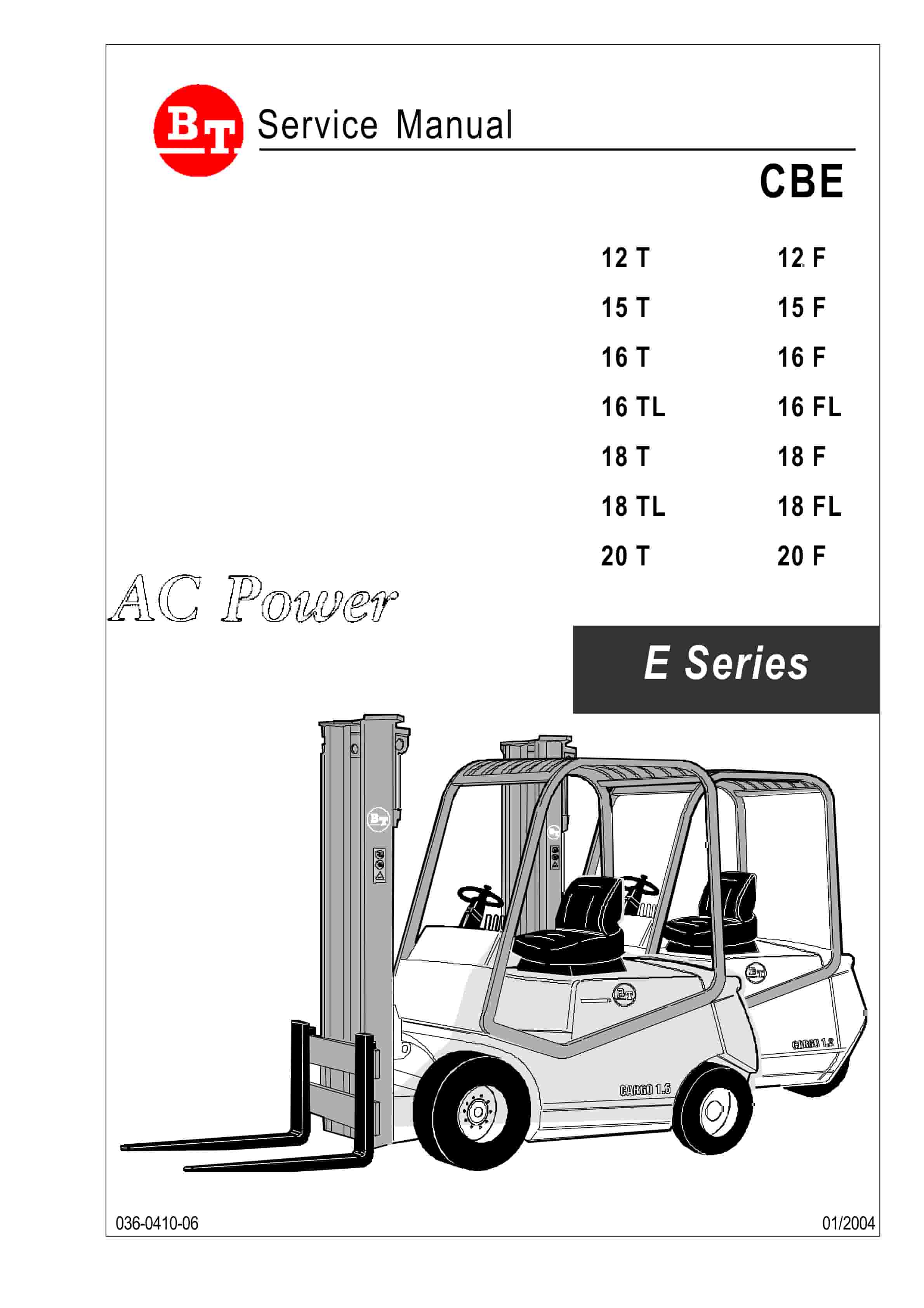
BT CBE 12T to CBE 20F Service Manual 036-0410-03
$30.00 Add to cart -
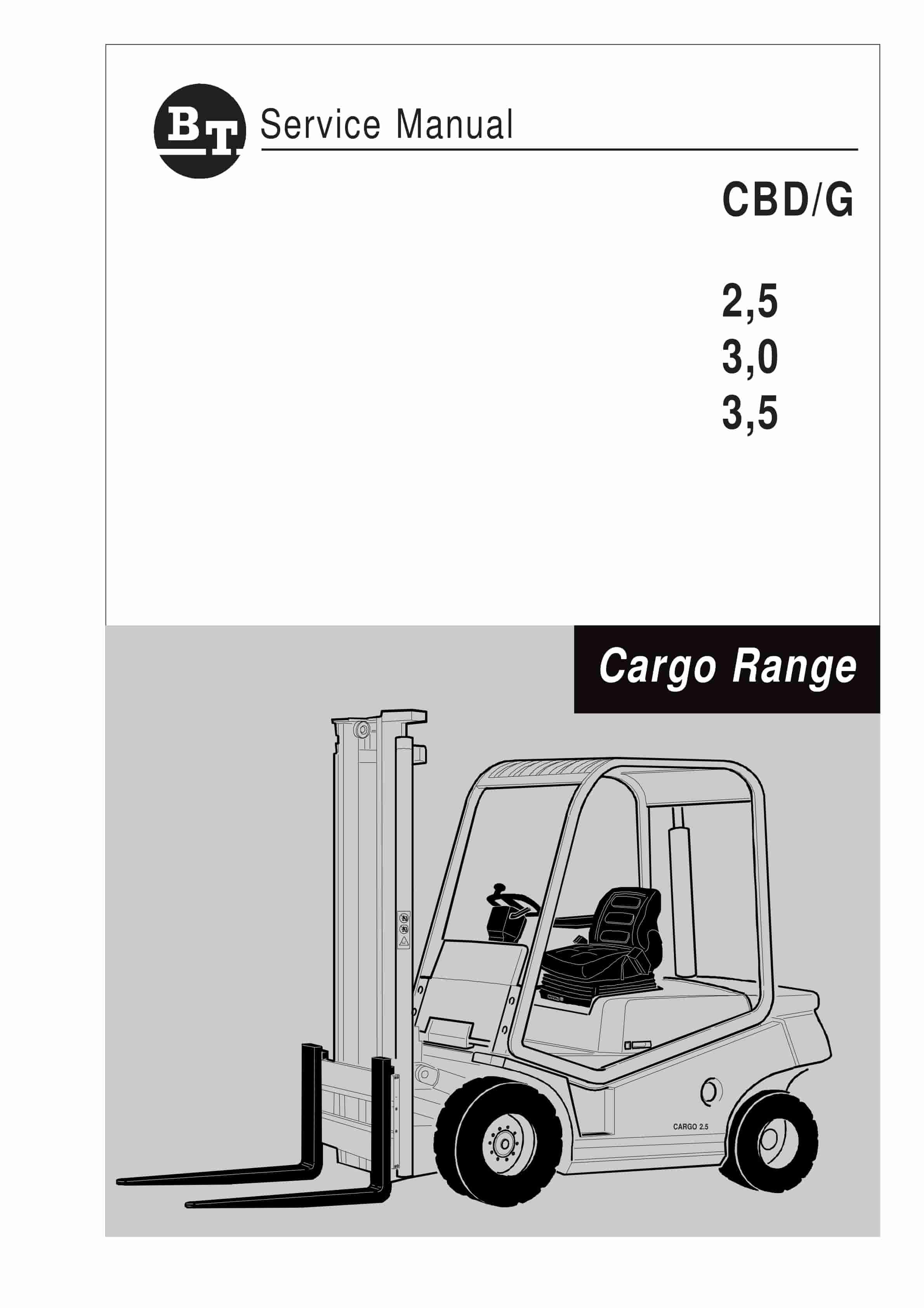
BT CBD-G 2.5, 3.0, 3.5 Service Manual 036-0405-01
$30.00 Add to cart -
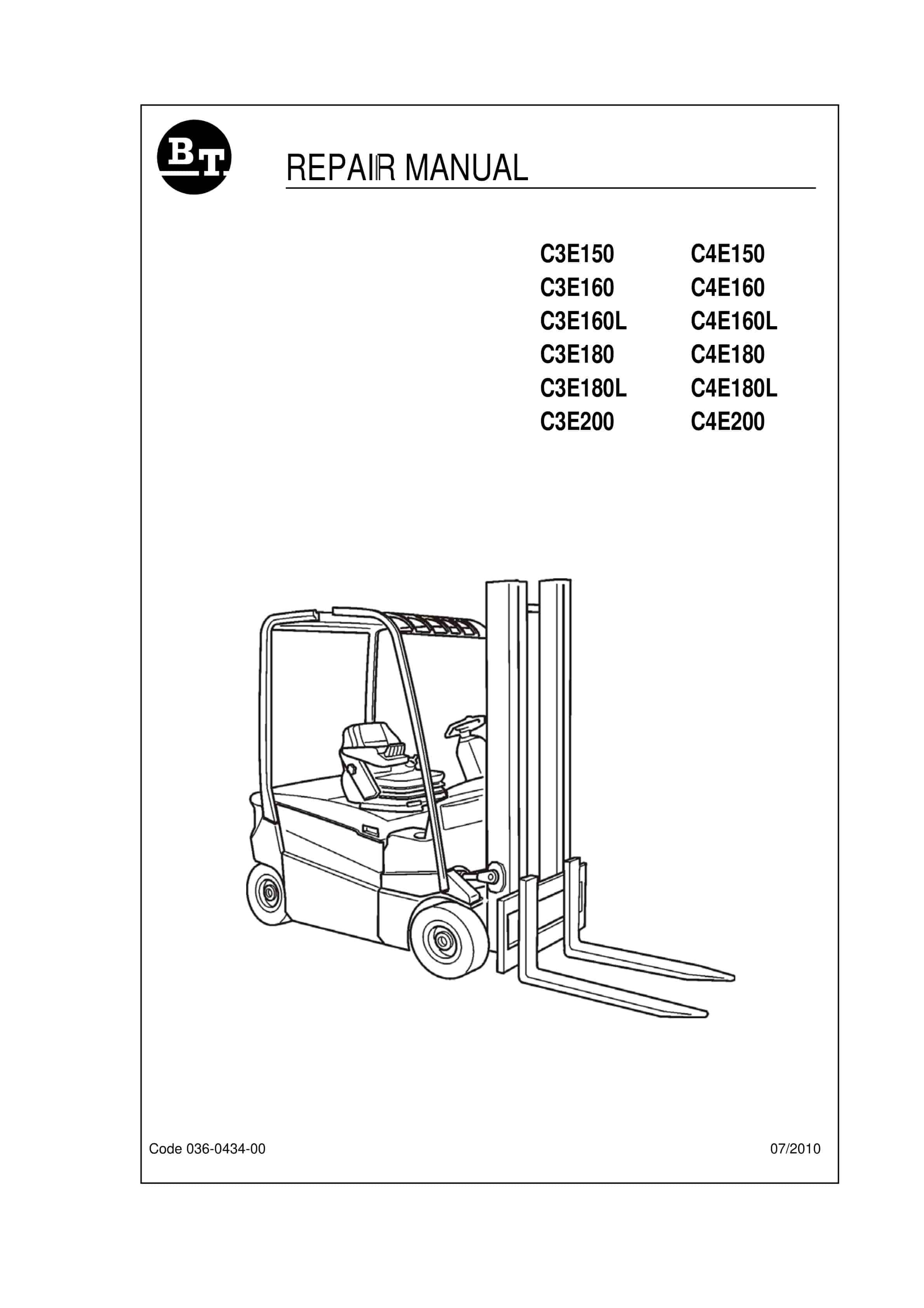
BT C3E150 to C4E200 Repair Manual 036-0434-00
$30.00 Add to cart -
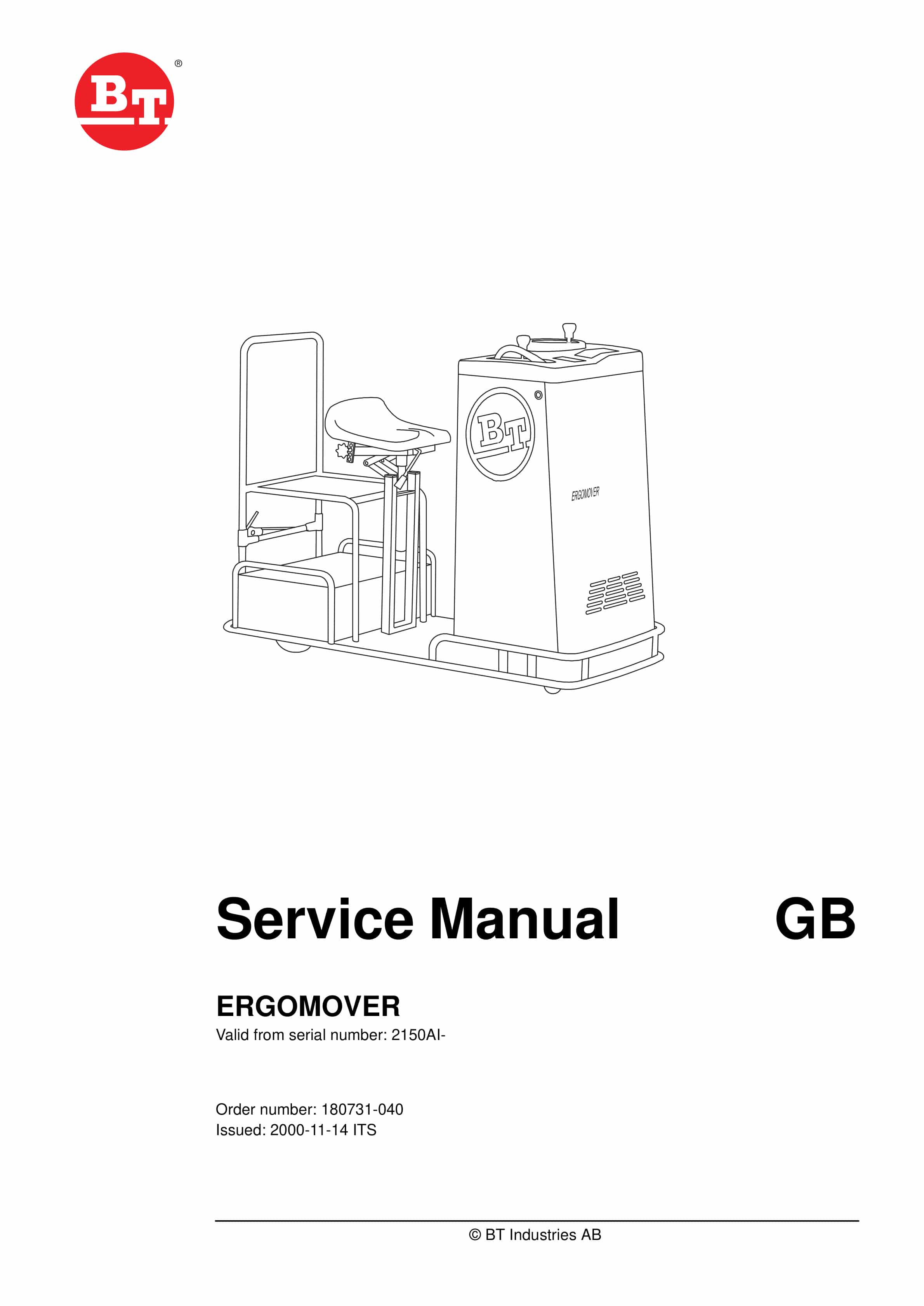
BT ERGOMOVER Service Manual 180731-040
$30.00 Add to cart -
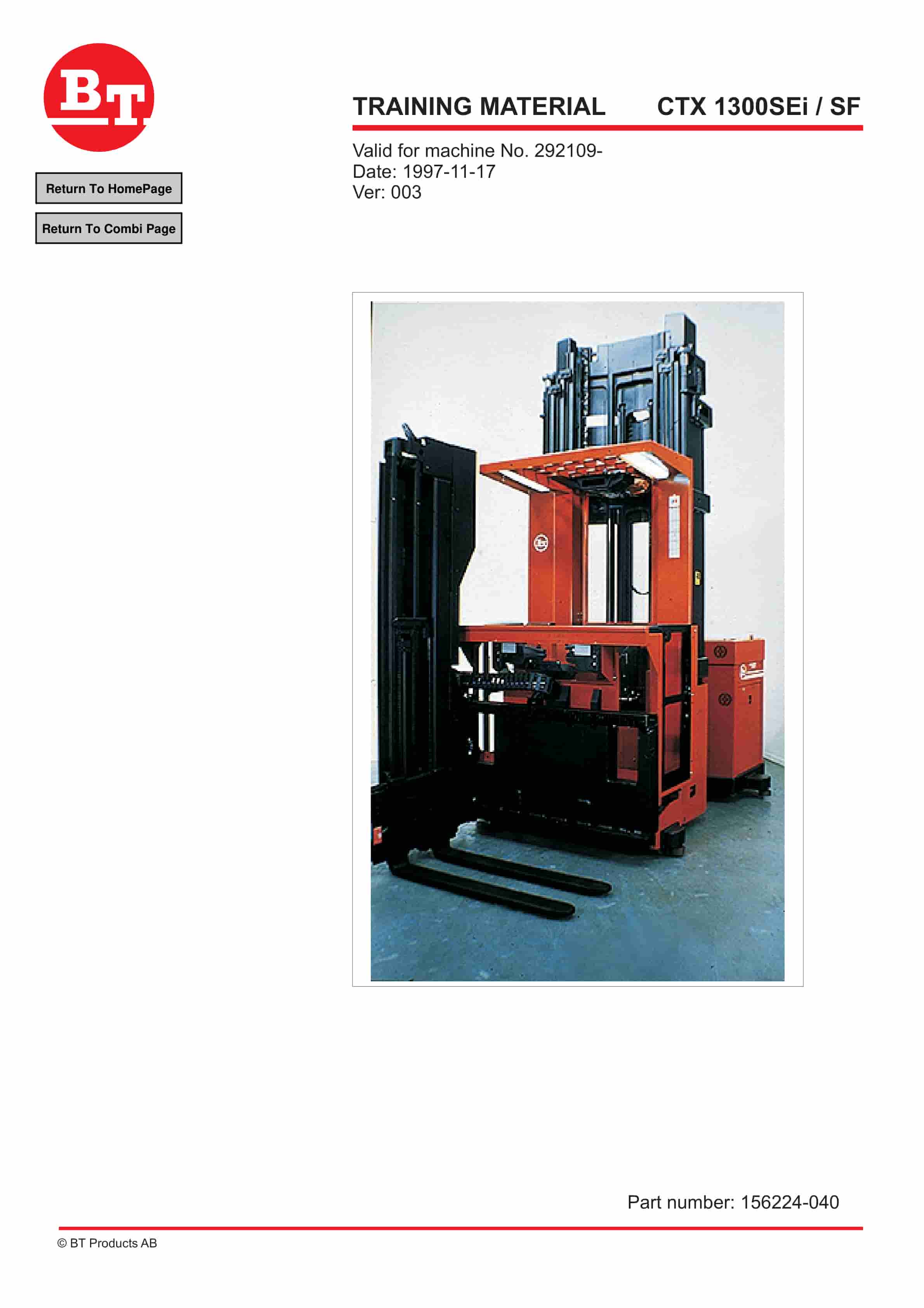
BT CTX 1300SEi, CTX 1300SEi SF Training Material 156224-040
$30.00 Add to cart


