


BT RR-34B Reach Truck Parts Manual 300377-002
$30.00
- Type Of Manual: Parts Manual
- Manual ID: 300377-002
- : Parts Manual PDF
- Number of Pages: 220
- Size: 5.1MB
- Format: PDF
Product details
-
Model List:
- RR-34B Reach Truck
- 1. Front Cover
- 2. Parts Ordering Instructions
- 3. Field Modifications
- 4. General Information
- 5. Alphabetical Index
- 6. Section 0.0
- 6.1. Figure 0.1 Decals and Parts Assembly
- 7. Section 1.0
- 7.1. Figure 1.1 Transmission and Drive Motor Installation
- 7.2. Figure 1.2 Drive Motor and Brake Assembly
- 7.3. Figure 1.3 Transmission Assembly Part 1
- 7.4. Figure 1.4 Transmission Assembly Part 2
- 8. Section 2.0
- 8.1. Figure 2.1 E EV-100LX SCR Electrical Schematic
- 8.2. Figure 2.2 E EV-100LX SCR Electrical Schematic Symbols
- 8.3. Figure 2.3 EE EV-100LX SCR Electrical Schematic
- 8.4. Figure 2.4 EE EV-100LX SCR Electrical Schematic Symbols
- 8.5. Figure 2.5 Wiring Assembly for Cold Storage
- 8.6. Figure 2.6 Wiring Harness Assembly
- 8.7. Figure 2.7 Limit Switch Wiring Assembly
- 8.8. Figure 2.8 Two Stage Mast Cable Assembly
- 8.9. Figure 2.9 Three Stage Mast Cable Assembly
- 8.10. Figure 2.10 Reach Cable Assembly
- 8.11. Figure 2.11 EV-100LX Power Component Wiring
- 8.12. Figure 2.12 EV-100LX TX TT SCR Control Panel Assembly
- 8.13. Figure 2.13 EV-100LX Contactor Panel Assembly Related Parts for E and EE
- 8.14. Figure 2.14 EV-100LX Contactor Panel Assembly
- 8.15. Figure 2.15 EV-100LX SCR Forward Rearward Contactor Assembly
- 8.16. Figure 2.16 EV-100LX SCR 1A Contactor Assembly
- 8.17. Figure 2.17 Lift Pump Contactor Assembly
- 8.18. Figure 2.18 EV-100LX SCR Auxiliary Pump Contactor Assembly
- 8.19. Figure 2.19 Power Connector Assembly
- 8.20. Figure 2.20 E EE 24 Volt Lift Pump Motor Assy
- 8.21. Figure 2.21 E 36 Volt Lift Pump Motor Assy
- 8.22. Figure 2.22 EE 36 Volt Lift Pump Motor Assembly
- 8.23. Figure 2.23 Drive Motor Assembly
- 8.24. Figure 2.24 Auxiliary Pump Motor Assembly
- 8.25. Figure 2.25 Warning Light Assembly
- 8.26. Figure 2.26 E EV-100LX TT SCR Electrical Schematic
- 8.27. Figure 2.27 E EV-100LX TT SCR Electrical Schematic Symbols
- 8.28. Figure 2.28 EE EV-100LX TT SCR Electrical Schematic
- 8.29. Figure 2.29 EE EV-100LX TT SCR Electrical Schematic Symbols
- 8.30. Figure 2.30 EV-100LX Dash Display Installation
- 8.31. Figure 2.31 EV-100LX SCR Electrical Schematic – 3 Function Control Handle
- 8.32. Figure 2.32 EV-100LX SCR Electrical Schematic Symbols
- 8.33. Figure 2.33 Wiring Harness Assembly for 3 Function Control Valve
- 9. Section 3.0
- 9.1. Figure 3.1 Hydraulic Schematic
- 9.2. Figure 3.2 Hydraulic Schematic Symbols
- 9.3. Figure 3.3 Auxiliary Pump and Reservoir Assembly
- 9.4. Figure 3.4 Auxiliary control Valve Assembly
- 9.5. Figure 3.5 Auxiliary Pump and Motor Assembly
- 9.6. Figure 3.6 Auxiliary Pump Assembly
- 9.7. Figure 3.7 Hydraulic Reservoir Assembly
- 9.8. Figure 3.8 Torque Generator Assembly
- 9.9. Figure 3.9 Two Stage Mast Hydraulic Assembly
- 9.10. Figure 3.10 Three Stage Mast Hydraulic Assembly
- 9.11. Figure 3.11 Single Reach, Reach Cylinder Hose Installation
- 9.12. Figure 3.12 Reach Diverter Valve Assembly
- 9.13. Figure 3.13 Reach Cylinder Assembly
- 9.14. Figure 3.14 Tilt and Sideshift Hose Installation
- 9.15. Figure 3.15 Tilt Cylinder Assembly
- 9.16. Figure 3.16 Lift Pump and Reservoir Assembly
- 9.17. Figure 3.17 Lift Pump Motor Assembly
- 9.18. Figure 3.18 Lift Pump Motor Assembly, 24 Volt
- 9.19. Figure 3.19 Lift Pump Motor Assembly, 36 Volt
- 9.20. Figure 3.20 Lift Control Valve Assembly
- 9.21. Figure 3.21 Two Stage Cylinder and Reservoir Assembly
- 9.22. Figure 3.22 Two Stage Cylinder Assembly
- 9.23. Figure 3.23 Three Stage Cylinder and Reservoir Assembly
- 9.24. Figure 3.24 Three Stage Staging Cylinder Assembly
- 9.25. Figure 3.25 Three Stage Freelift Cylinder Assembly
- 9.26. Figure 3.26 Hydraulic Schematic for 3 Function Control Handle
- 9.27. Figure 3.27 Hydraulic Schematic Symbols
- 9.28. Figure 3.28 Auxiliary Pump Reservoir Assy for 3 Function Control Handle
- 9.29. Figure 3.29 Valve Assembly
- 9.30. Figure 3.30 Two Stage Mast Hydraulic Assy for 3 Function Control Handle
- 9.31. Figure 3.31 Three Stage Mast Hydraulic Assy for 3 Function Control Handle
- 10. Section 4.0
- 10.1. Figure 4.1 Shielding Assembly
- 10.2. Figure 4.2 Emergency Disconnect Assembly
- 10.3. Figure 4.3 Auxiliary Control Assembly
- 10.4. Figure 4.4 Hand Lift/Lower and Speed Control
- 10.5. Figure 4.5 Forward Steering Control Assembly
- 10.6. Figure 4.6 Rearward Steering Control Assembly
- 10.7. Figure 4.7 Auxiliary Pump and Motor Installation
- 10.8. Figure 4.8 Main Frame and Load Wheel Assembly
- 10.9. Figure 4.9 Single Load Wheel Assembly
- 10.10. Figure 4.10 5 High Articulating Load Wheel Assembly
- 10.11. Figure 4.11 4 High Articulating Load Wheel Assembly
- 10.12. Figure 4.12 Caster Assembly
- 10.13. Figure 4.13 Hand Lift/Lower and Speed Control for 3 Function Control
- 11. Section 5.0
- 11.1. Figure 5.1 Two Stage Mast Installation
- 11.2. Figure 5.2 Two Stage Inner Column Assembly
- 11.3. Figure 5.3 Two Stage Outer Column Assembly
- 11.4. Figure 5.4 Two Stage Cylinder Assembly
- 11.5. Figure 5.5 Two Stage Reach Assembly
- 11.6. Figure 5.6 Two Stage Reach Front Frame
- 11.7. Figure 5.7 Two Stage Sideshifter Assembly
- 11.8. Figure 5.8 Two Stage Fork Assembly
- 11.9. Figure 5.9 Three Stage Mast Installation
- 11.10. Figure 5.10 Three Stage Inner Column Assembly
- 11.11. Figure 5.11 Three Stage Freelift Cylinder Installation
- 11.12. Figure 5.12 Three Stage Intermediate Column Assembly
- 11.13. Figure 5.13 Three Stage Outer Column Assembly
- 11.14. Figure 5.14 Three Stage Single Reach Assembly
- 11.15. Figure 5.15 Three Stage Single Reach Front Frame Assembly
- 11.16. Figure 5.16 Three Stage Sideshifter Assy
- 11.17. Figure 5.17 Three Stage Fork Assembly
- 12. Section 7.0
- 12.1. Figure 7.1 Battery Lift Interrupt E EV-100LX SCR Electrical Schematic
- 12.2. Figure 7.2 Battery Lift Interrupt E EV-100LX SCR Electrical Schematic Symbols
- 12.3. Figure 7.3 Battery Lift Interrupt EE EV-100LX SCR Electrical Schematic
- 12.4. Figure 7.4 Battery Lift Interrupt EE EV-100LX SCR Electrical Schematic Symbols
- 12.5. Figure 7.5 Battery Lift Interrupt Installation
- 13. Section 10.0
- 13.1. Figure 10.1 Special Tools and Lubrications
- 14. Numerical Index
- 15. Back Cover
Related products
-
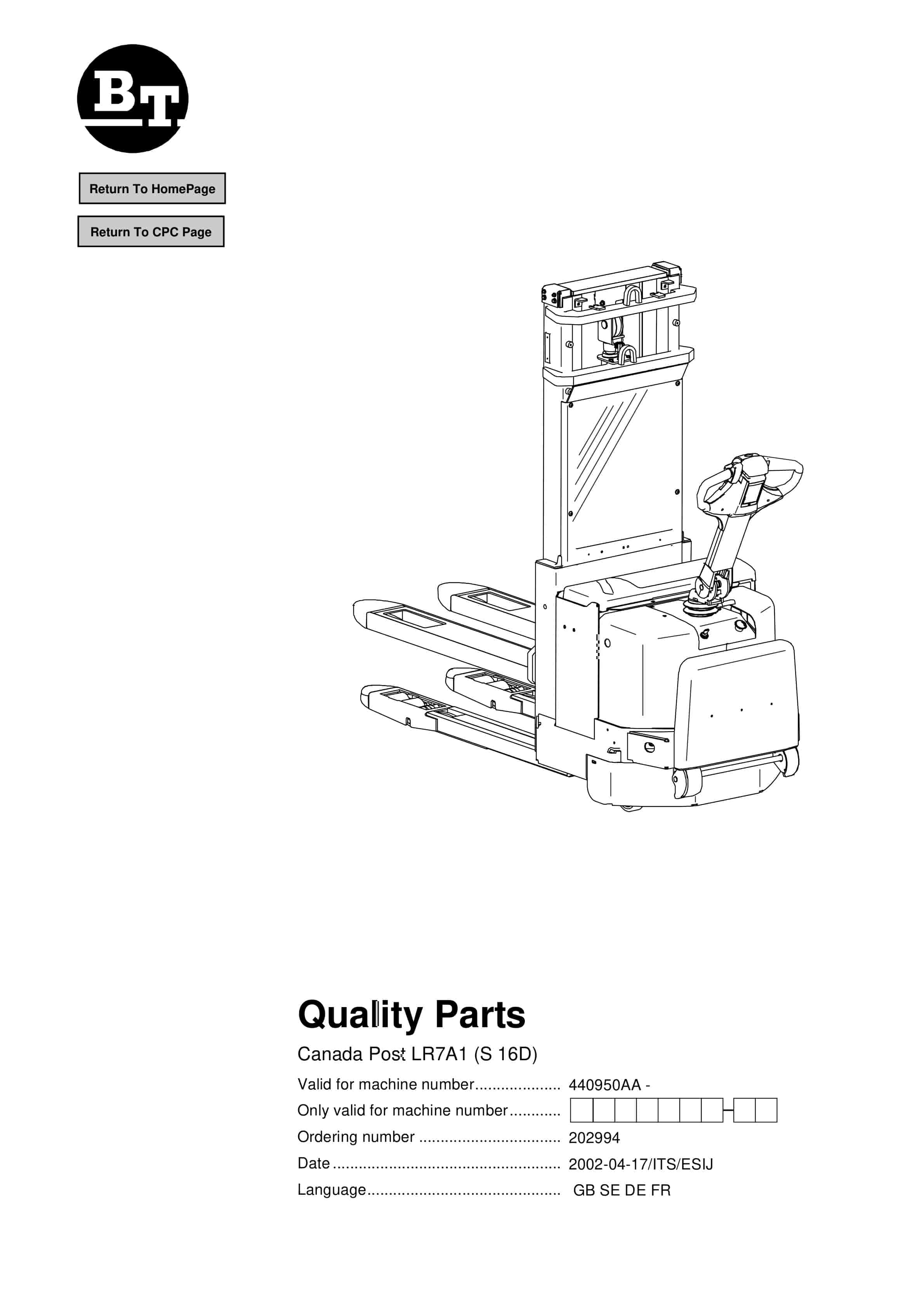
BT Canada Post LR7A1 (S 16D) Quality Parts 202994
$30.00 Add to cart -
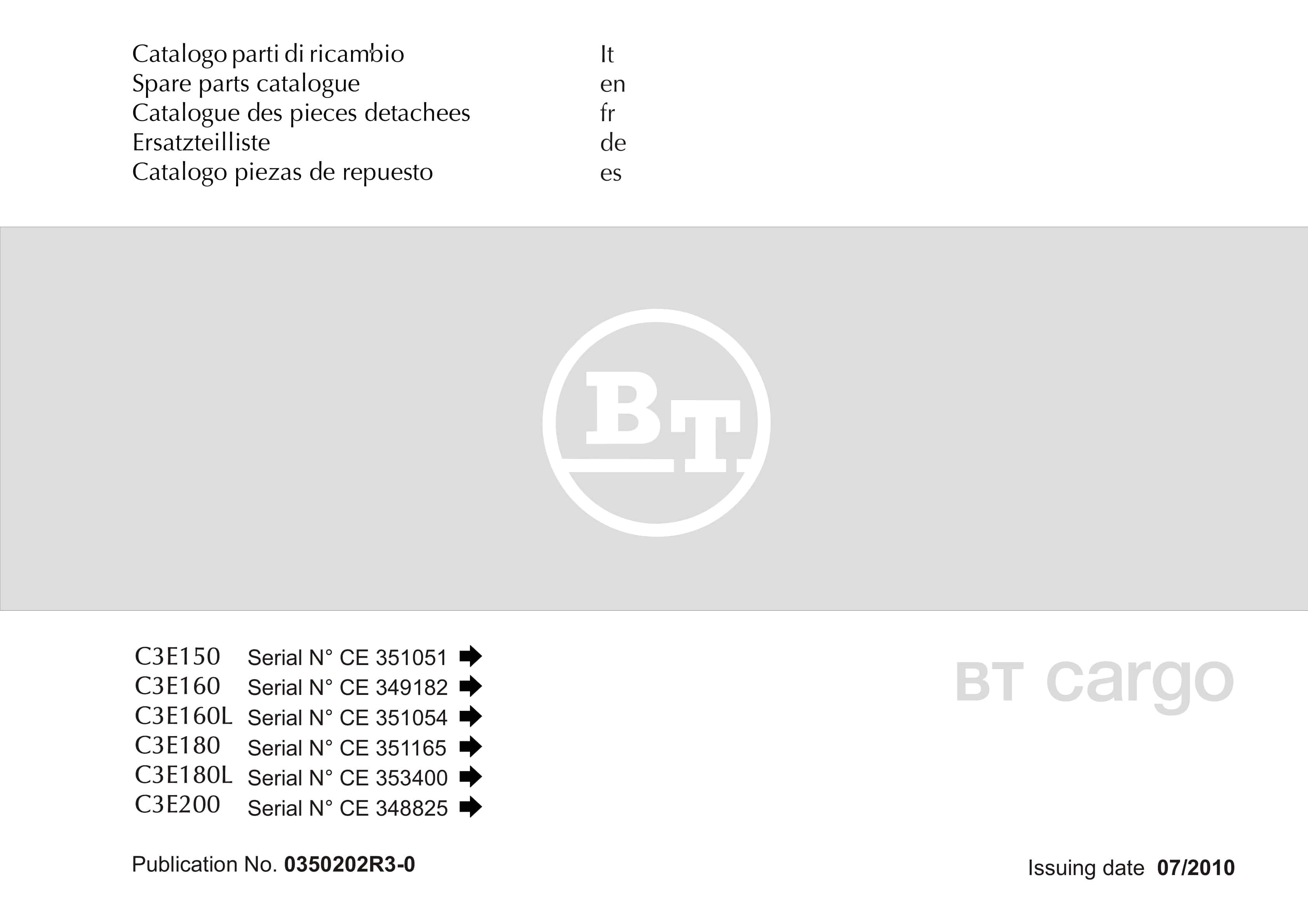
BT C3E150, C3E160, C3E160L, C3E180, C3E180L, C3E200 Spare Parts Catalog 0350202R3-0
$30.00 Add to cart -
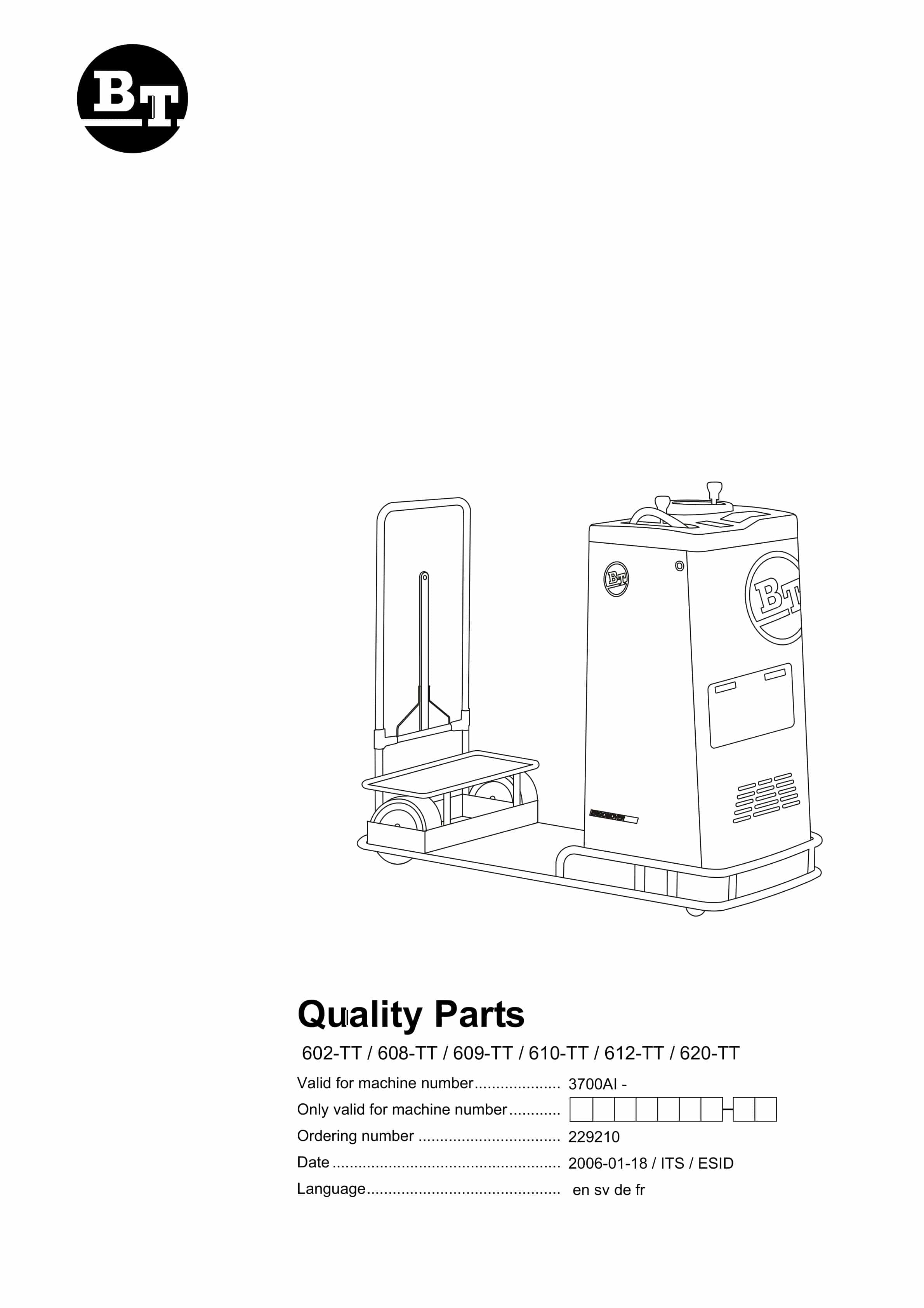
BT 602-TT, 608-TT, 609-TT, 610-TT, 612-TT, 620-TT Quality Parts 229210
$30.00 Add to cart -
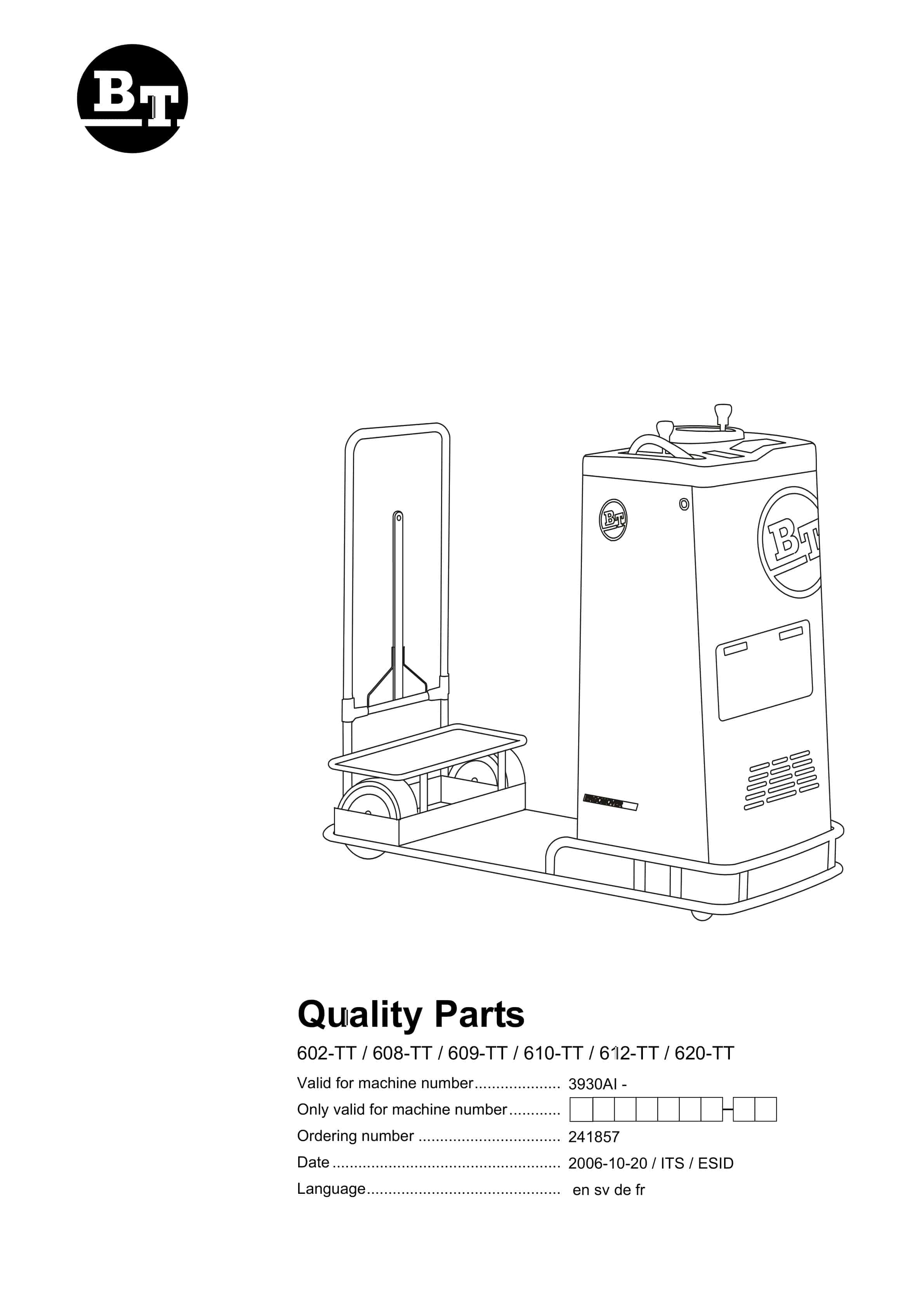
BT 602-TT, 608-TT, 609-TT, 610-TT, 612-TT, 620-TT Quality Parts 241857
$30.00 Add to cart -
BT CARGO C3E 160 DC Spare Parts Catalog 0350191R1-0
$30.00 Add to cart
%20Quality%20Parts%20202994&url=https://ownersmanualpdf.net/docs/bt-canada-post-lr7a1-s-16d-quality-parts-202994/&media=https://ownersmanualpdf.net/wp-content/uploads/2025/12/bt-canada-post-lr7a1-s-16d-quality-parts-202994-1.jpg)