


BT RR-40 Reach Truck Operating – Maintenance – Parts Manual 302091-000
$30.00
- Type Of Manual: Operating – Maintenance – Parts Manual
- Manual ID: 302091-000
- : Parts Manual PDF
- Number of Pages: 118
- Size: 5.4MB
- Format: PDF
Product details
-
Model List:
- RR-40 Reach Truck
- 1. Front Cover
- 2. Warranty
- 3. New Owners
- 4. Contents
- 5. Preliminary Service
- 6. Operation
- 7. Operating Rules and Instructions
- 8. Lubrication Chart
- 9. Maintenance Instructions
- 10. Service and Disassembly Instructions
- 11. Parts Ordering Instructions
- 12. Truck Specifications
- 13. Figure 1 Decal and Part Assembly
- 14. Figure 2 Parts List and Service Reference Index
- 15. Figure 3 Shield Assembly
- 16. Figure 4 Emergency Disconnect and Auxiliary Control Assembly
- 17. Figure 5 Hand Lift and Speed Assembly
- 18. Figure 6 Master Control Switch Assembly
- 19. Figure 7 Steering Control and Pump Assembly
- 20. Figure 8 Auxiliary Pump Assembly
- 21. Figure 9 Auxiliary Motor Assembly
- 22. Figure 10 Transmission and Steering Insulation Assembly
- 23. Figure 11 Brake Assembly
- 24. Figure 12 Drive Motor Assembly
- 25. Figure 13 Transmission Assembly
- 26. Figure 14 Idler Wheel Insulation Assembly
- 27. Figure 15 Electrical Schematic
- 28. Figure 16 Electrical Schematic Symbols
- 29. Figure 17 Wiring Harness Assembly
- 30. Figure 18 Mast Cable Assembly
- 31. Figure 19 Reach Cable Assembly
- 32. Figure 20 Power Component Wiring
- 33. Figure 21 SCR and Contactor Panel Assembly
- 34. Figure 22 EV-1 SCR Control
- 35. Figure 23 Transformer Assembly
- 36. Figure 24 Rectifier Heat Sink Assembly
- 37. Figure 25 GE Contactor Assembly
- 38. Figure 26 Power Steering Contactor Assembly
- 39. Figure 27 GE Contactor Assembly
- 40. Figure 28 Hydraulic Schematic
- 41. Figure 29 Hydraulic Schematic Symbols
- 42. Figure 30 Hydraulic Assembly Part 1
- 43. Figure 31 Brake Solenoid Valve
- 44. Figure 32 Brake Cylinder Assembly
- 45. Figure 33 Hydraulic Reservoir Assembly
- 46. Figure 34 Hydraulic Assembly Part 2
- 47. Figure 35 Lift Pump and Motor Assembly
- 48. Figure 36 Lift Motor Assembly
- 49. Figure 37 Lift Pump Assembly
- 50. Figure 38 Lift Control Valve Assembly
- 51. Figure 39 Hydraulic Assembly Part 3
- 52. Figure 40 Steer Control Valve
- 53. Figure 41 Steer Cylinder Assembly
- 54. Figure 42 Auxiliary Control Valve Assembly
- 55. Figure 43 Hydraulic Assembly Part 4
- 56. Figure 44 Freelift Cylinder Assembly
- 57. Figure 45 Staging Cylinder Assembly
- 58. Figure 46 Mast Hydraulic Hose Assembly
- 59. Figure 47 Standard Reach Hose Assembly
- 60. Figure 48 Reach and Tilt Cylinder Assembly
- 61. Figure 49 Reach with Tilt Hose Assembly
- 62. Figure 50 Reach with Tilt Manifold Valve Assembly
- 63. Figure 51 Sideshifter Hose Assembly
- 64. Figure 52 Sideshifter Cylinder Assembly
- 65. Figure 53 Sideshifter Manifold Valve
- 66. Figure 54 3 Stage Mast Insulation Assembly
- 67. Figure 55 Outer Column Assembly
- 68. Figure 56 Intermediate Column Assembly
- 69. Figure 57 Inner Column Assembly
- 70. Figure 58 3 Stage Freelift Cylinder Assembly
- 71. Figure 59 Reach Assembly
- 72. Figure 60 Standard Reach Front Frame Assembly
- 73. Figure 61 Tilt Reach Front Frame Assembly
- 74. Figure 62 Fork Assembly
- 75. Figure 63 Sideshifter Assembly
- 76. Figure 64 Main Frame and Load Wheel Assembly
- 77. Service Guide
- 78. Back Cover
Related products
-
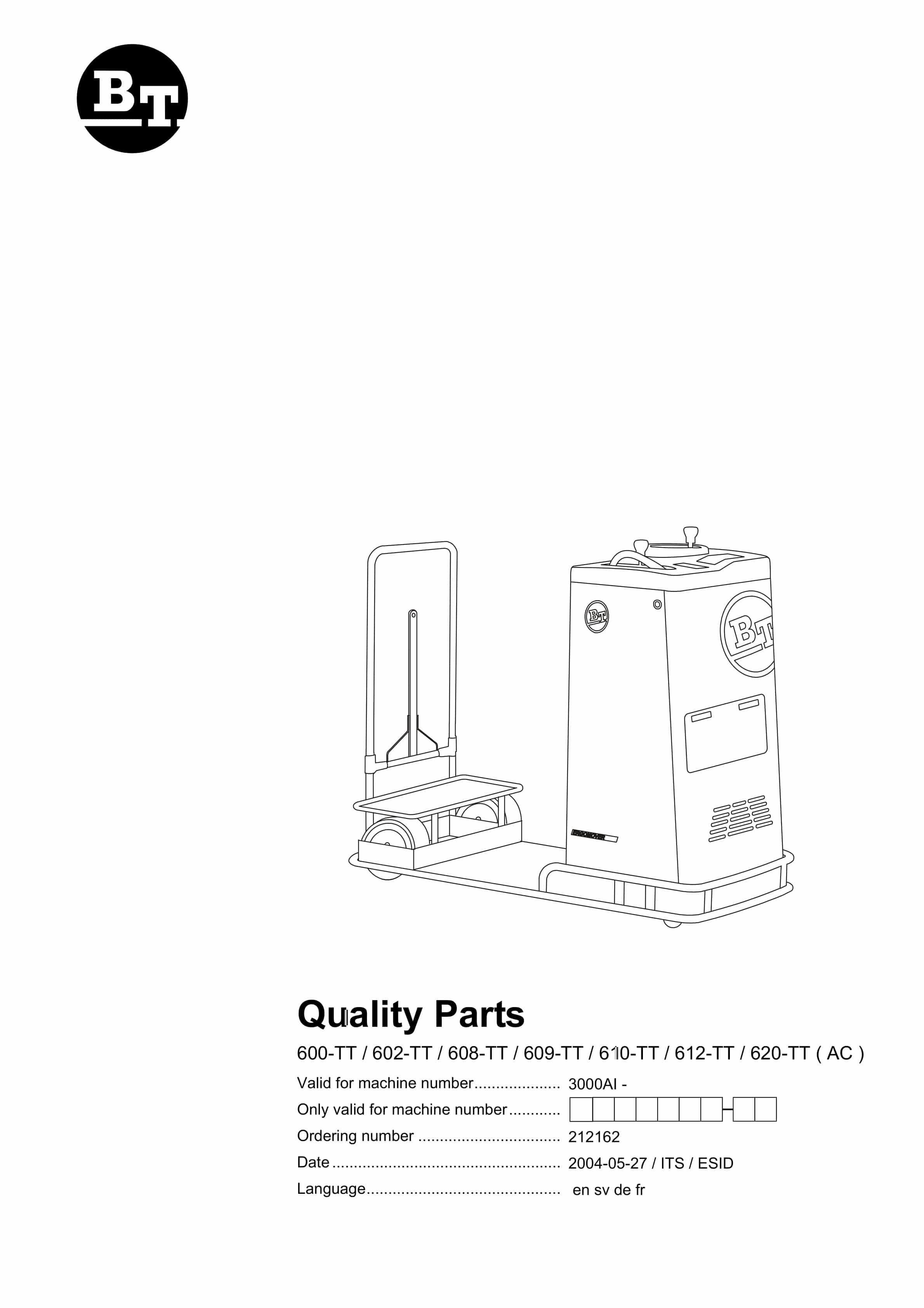
BT 600-TT, 602-TT, 608-TT, 609-TT, 610-TT, 612-TT, 620-TT (AC) Quality Parts 212162
$30.00 Add to cart -
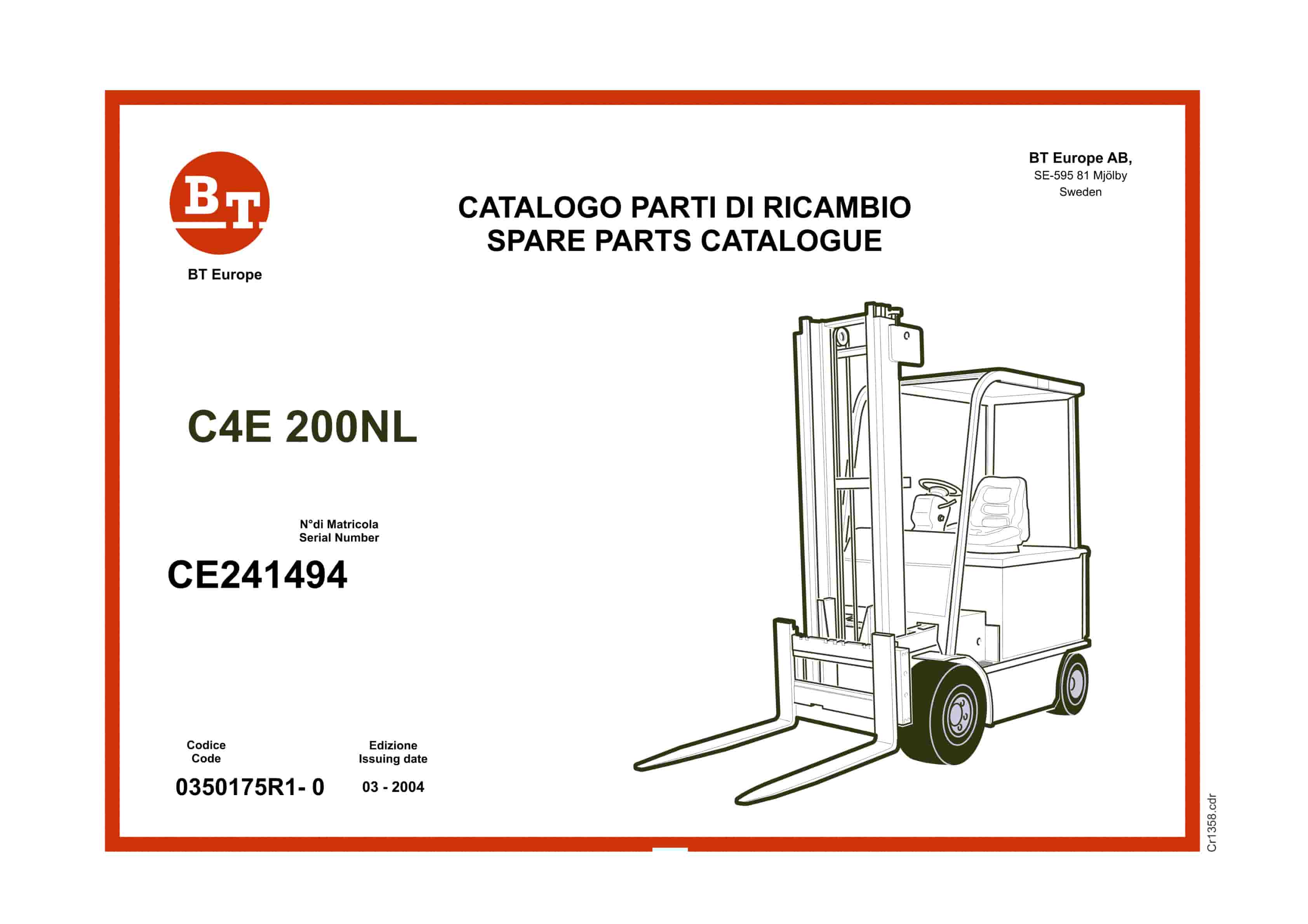
BT C4E 200NL Spare Parts Catalog 0350175R1-0
$30.00 Add to cart -
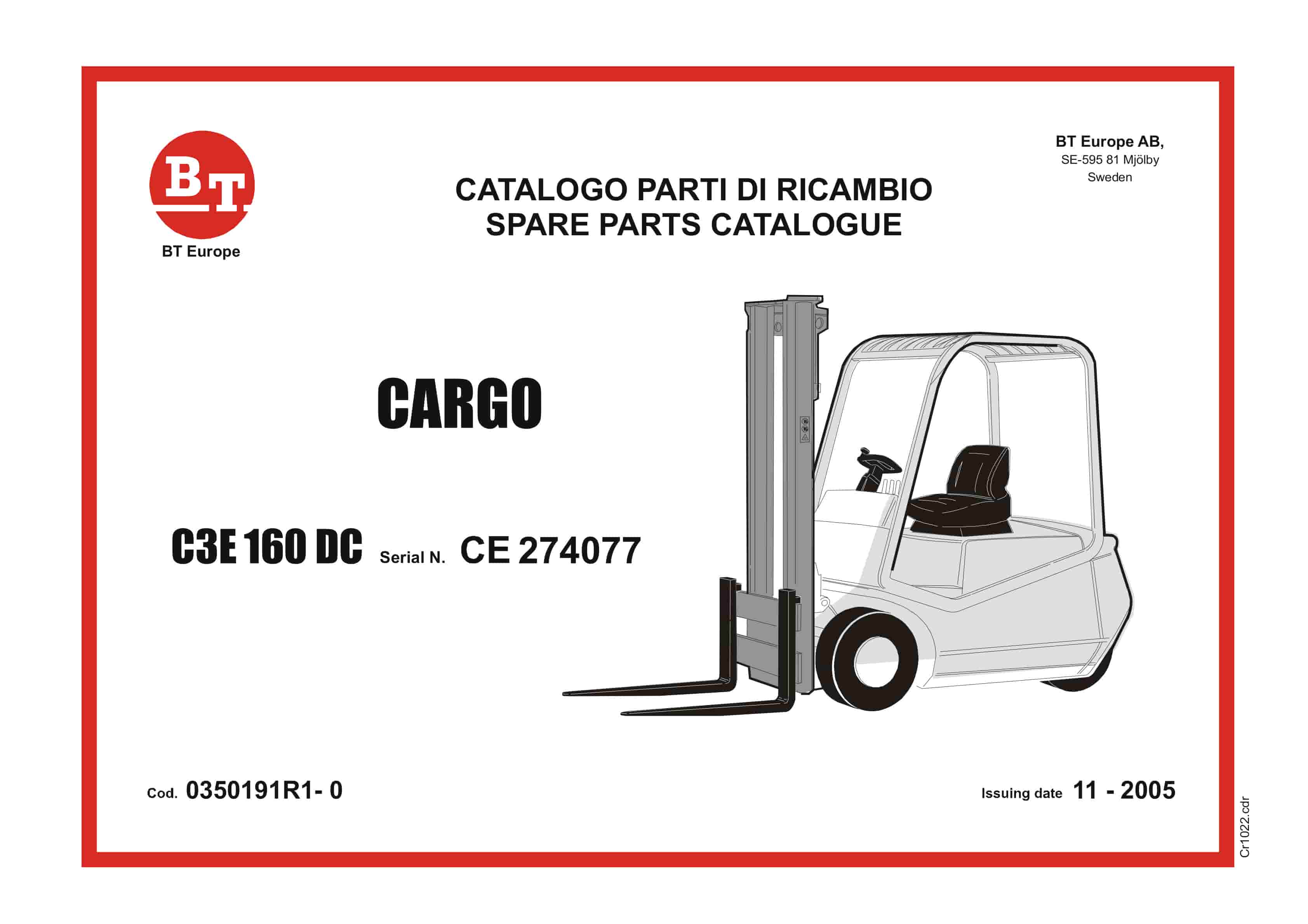
BT CARGO C3E 160 DC Spare Parts Catalog 0350191R1-0
$30.00 Add to cart -
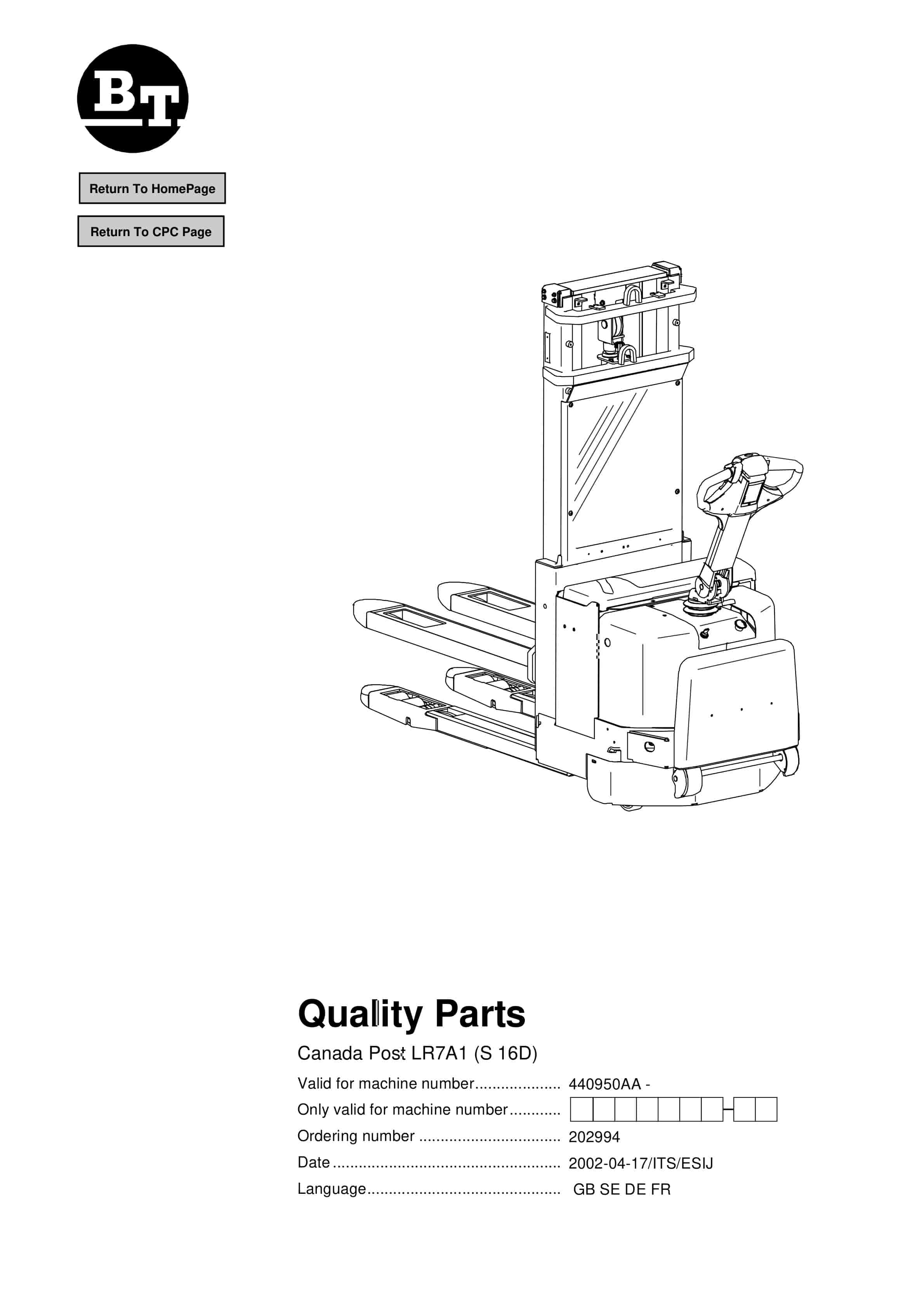
BT Canada Post LR7A1 (S 16D) Quality Parts 202994
$30.00 Add to cart -
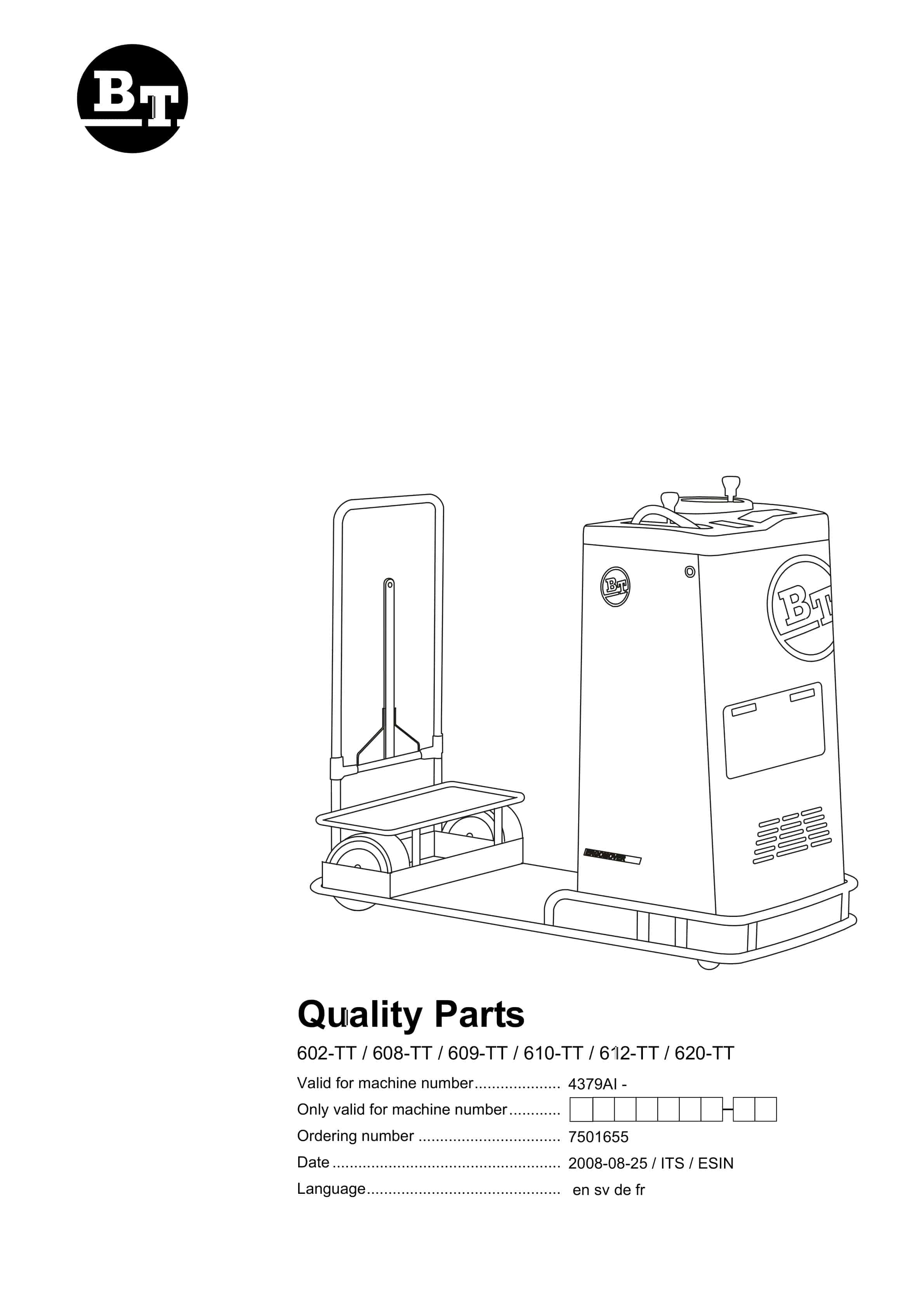
BT 602-TT, 608-TT, 609-TT, 610-TT, 612-TT, 620-TT Quality Parts 7501655
$30.00 Add to cart
%20Quality%20Parts%20212162&url=https://ownersmanualpdf.net/docs/bt-600-tt-602-tt-608-tt-609-tt-610-tt-612-tt-620-tt-ac-quality-parts-212162/&media=https://ownersmanualpdf.net/wp-content/uploads/2025/12/bt-600-tt-602-tt-608-tt-609-tt-610-tt-612-tt-620-tt-ac-quality-parts-212162-1.jpg)
%20Quality%20Parts%20202994&url=https://ownersmanualpdf.net/docs/bt-canada-post-lr7a1-s-16d-quality-parts-202994/&media=https://ownersmanualpdf.net/wp-content/uploads/2025/12/bt-canada-post-lr7a1-s-16d-quality-parts-202994-1.jpg)