


BT RTX35, RTX45 Electric Stand-Up Rider Truck Service Manual 310428-000
$30.00
- Type Of Manual: Service Manual
- Manual ID: 310428-000
- : Service Manual PDF
- Number of Pages: 542
- Size: 26.7MB
- Format: PDF
Product details
-
Model List:
- RTX35, RTX45 Electric Stand-Up Rider Truck
- 1. BT Prime-Mover Standard Codes
- 1.1. Worksheet standard
- 1.2. C-Code List
- 2. Warning Symbols
- 2.1. Warning Levels
- 3. Prohibitory Symbols
- 3.1. NO SMOKING
- 3.2. OPEN FLAMES PROHIBITED
- 3.3. GENERAL PROHIBITION
- 3.4. Ordinance Symbols
- 3.5. General Safety
- 4. Battery Safety
- 5. Static Safety
- 5.1. Place a static discharge wrist strap around your wrist. Connect the ground lead to the wrist s…
- 5.2. Connect the ground clamp to an unpainted, grounded surface on the truck frame.
- 5.3. If removing or installing static-sensitive components, place them on a properly grounded stati…
- 5.4. To transport static-sensitive components, including failed components being returned, place th…
- 6. Welding Safety
- 7. Introduction, Service Manual
- 8. Contents, Section M
- 8.1. Machine Information
- 9. General Product Information
- 9.1. Truck Presentation
- 9.2. Main Components
- 9.3. Grease Point Location
- 9.4. Mast Adjustment Points
- 10. Inch (SAE) and Metric Fasteners
- 10.1. Introduction
- 10.2. Nomenclature, Threads
- 10.3. Strength Identification
- 10.4. Conversion of Metric and English Units
- 11. Technical Service Data
- 11.1. RTX35 (192 inch mast)
- 11.2. RTX45 (210 inch mast)
- 11.3. Series – DC
- 11.4. Series – DC
- 11.5. hp/3.725 kw (24 volt drive motor) 6.25 hp/4.66 kw (36 volt drive motor) 16hp/11.9 kw (36 volt l…
- 11.6. hour continuous
- 11.7. hour continuous
- 11.8. inch (20 mm)
- 11.9. inch (20 mm)
- 11.10. inches (74 mm)
- 11.11. inches (74 mm)
- 11.12. oz. (180 grams)
- 11.13. oz. (180 grams)
- 11.14. Vertical motor spiral-bevel output
- 11.15. Vertical motor spiral-bevel output
- 11.16. gallons (3.79 liters)
- 11.17. gallons (3.79 liters)
- 11.18. SAE 80W90
- 11.19. SAE 80W/90
- 11.20. SAE 80W90
- 11.21. SAE 80W/90
- 11.22. x 5.5 x 10.0 inches (343 x 140 x 254 mm)
- 11.23. x 5.5 x 10.0 inches (343 x 140 x 254 mm)
- 11.24. lb battery 14.5 BC – 6735 (3054) 2000 lb battery 16.5 BC – 4315 (1959)
- 11.25. lb battery 16.5 BC – 4750 (2156) 2400 lb battery 21 BC – 4910 (2229)
- 11.26. lb battery 14.5 BC – 3240 (1471) 2000 lb battery 16.5 BC – 3430 (1557)
- 11.27. lb battery 16.5 BC – 3780 (1716) 2400 lb battery 21 BC – 4025 (1827)
- 11.28. ft-lb (130 Nm)
- 11.29. ft-lb (130 Nm)
- 11.30. x 3.6 inches (127 x 91 mm)
- 11.31. x 3.6 inches (127 x 91 mm)
- 11.32. lb battery 14.5 BC – 6860 (3114 2000 lb battery 16.5 BC – 7145 (3244)
- 11.33. lb battery 16.5 BC – 8595 (3902) 2400 lb battery 21 BC – 8690 (3945)
- 11.34. Amp 400 Amp
- 11.35. Not Applicable (N/A) 425 Amp
- 11.36. empty-750 loaded 36V – 2100 empty-1500 loaded
- 11.37. empty-1450 loaded
- 11.38. volt 11.6 HP with 20 duty cycle
- 11.39. on 5 minute cycles
- 11.40. inch (20 mm)
- 11.41. inch (16 mm)
- 11.42. inches (74 mm)
- 11.43. inches (72 mm)
- 11.44. oz (180 grams)
- 11.45. oz (1120 grams)
- 11.46. psi (16890 kPa)
- 11.47. psi (16890 kPa)
- 11.48. cc upper/4 cc lower
- 11.49. cc upper/4 cc lower 8 cc upper/4 cc lower
- 11.50. cc upper/4 cc lower 11 cc upper/4 cc lower
- 11.51. gallons (19 liters)
- 11.52. gallons (19 liters)
- 11.53. Sunoco TH
- 11.54. Texaco 15
- 11.55. Sunoco TH
- 11.56. Texaco 15
- 11.57. Amp
- 11.58. Amp
- 11.59. Amp
- 11.60. Amp
- 11.61. Amp
- 11.62. x 38.8 x 32.0 inches
- 11.63. (366 x 986 x 813 mm)
- 11.64. x 38.8 x 32.0 inches
- 11.65. (417 x 986 x 813 mm)
- 11.66. x 38.8 x 32.0 inches
- 11.67. (417 x 986 x 813 mm)
- 11.68. x 38.8 x 32.0 inches
- 11.69. (531 x 986 x 813 mm)
- 11.70. Amp hours
- 11.71. Amp hours 875 Amp hours
- 11.72. Amp hours 875 Amp hours
- 11.73. inches (368 mm) 1600 lb (726 kg)
- 11.74. (2300 lb / 1044 kg)
- 11.75. inches (419 mm) 2000 lb (908 kg)
- 11.76. (2300 lb / 1044 kg)
- 11.77. inches (419 mm) 2000 lb (908 kg)
- 11.78. (2300 lb / 1044 kg)
- 11.79. inches (533 mm) 2400 lb (1089 kg)
- 11.80. (2900 lb (1317 kg)
- 11.81. mph (9.65 kph)
- 11.82. mph (10.46 kph)
- 11.83. mph (10.46 kph)
- 11.84. mph (8.85 kph)
- 11.85. mph (9.65 kph)
- 11.86. mph (9.65 kph)
- 11.87. fpm (17.37 m/min.)
- 11.88. fpm (24.4 m/min.)
- 11.89. fpm (29 m/min.)
- 11.90. fpm (10.4 m/min.)
- 11.91. fpm (18.3 m/min.)
- 11.92. fpm (18.3 m/min.)
- 11.93. fpm (24.4 m/min.)
- 11.94. fpm (27.5 m/min.)
- 11.95. fpm (24.4 m/min.)
- 11.96. fpm (29 m/min.)
- 11.97. Amps
- 11.98. Amps
- 11.99. N/A 90 Amps
- 11.100. Amps
- 11.101. Amps
- 11.102. Amps
- 11.103. Amps
- 11.104. Amps
- 11.105. Amps
- 11.106. Amps
- 11.107. Amps
- 11.108. Amps
- 11.109. Amps
- 11.110. Amps
- 11.111. Amps
- 11.112. Amps
- 11.113. Amps
- 11.114. Amps
- 11.115. Amps
- 11.116. Amps
- 11.117. Amps
- 11.118. Amps
- 11.119. Amps
- 11.120. Amps
- 11.121. Amps
- 11.122. Amps
- 12. Ordering Spare Parts
- 12.1. Locate the fault on the truck.
- 12.2. Identify truck model, serial number, and battery voltage.
- 12.3. Locate the page with the exploded diagram and find the item number for the part required.
- 12.4. Locate the item number in the table. Select the column for the actual truck model and serial n…
- 12.5. Note the part number.
- 12.6. Call your local BT Prime-Mover Dealer and indicate the part number.
- 12.7. If the model, serial number, or the article number cannot be found on the truck, call your loc…
- 13. Contents, Section P
- 13.1. Planned Maintenance
- 14. Introduction, Maintenance
- 14.1. Safe Jacking Procedure
- 14.2. Lubricants
- 15. Service Schedule
- 15.1. Planned Maintenance Schedule
- 15.2. Planned Maintenance Procedures
- 16. Lubrication Chart
- 16.1. Interval/Running Hours
- 16.2. Lubricant
- 17. Oil and Grease Specifications
- 17.1. Approved Oils and Grease
- 18. Contents, Section S
- 18.1. Service Instructions
- 19. Troubleshooting Guidelines
- 19.1. General
- 19.2. Electrical
- 19.3. Hydraulic
- 19.4. Definitions
- 20. Chassis
- 20.1. General
- 20.2. Top Console
- 20.3. Motor Compartment Door
- 20.4. Left Side Panel (Exterior)
- 20.5. Left Operator Compartment Panel
- 20.6. Main Electronic Card Panel
- 20.7. Floor Board
- 20.8. Clipboard
- 21. Battery Retainer Plates and Rollers
- 21.1. Battery Retainer Plates
- 21.2. Battery Rollers
- 22. Mounting Points
- 22.1. Drive Motor
- 22.2. Pump Motor
- 22.3. Transmission
- 23. Driver Controls
- 23.1. Handle Interface Module
- 23.2. Control Handle
- 24. Brake Pedal (RTX35)
- 24.1. Pedal Removal
- 24.2. Pedal Bearing Replacement
- 24.3. Pedal Adjustment
- 25. Brake Pedal (RTX45)
- 25.1. Pedal Removal
- 25.2. Pedal Bearing Replacement
- 25.3. Pedal Adjustment
- 26. Internal Fittings
- 26.1. Operator Fan
- 26.2. Overhead Guard
- 26.3. Decal with Protective Sheet
- 26.4. Decal without Protective Sheet
- 27. Steering Motor
- 27.1. Removal
- 27.2. Installation
- 27.3. Steering Motor Gear Replacement
- 28. Fan Motor
- 28.1. Upper Electrical Compartment Fan
- 28.2. Operator Fan
- 29. Motor Maintenance Schedule/Troubleshooting
- 29.1. General Information
- 29.2. Operating Conditions
- 29.3. Troubleshooting
- 30. Pump Motor (RTX35)
- 30.1. Component Repair
- 30.2. Motor Inspection
- 31. Pump Motor (RTX 45)
- 31.1. Component Repair
- 31.2. Motor Inspection
- 32. Drive Motor
- 32.1. Motor Disassembly
- 32.2. Motor Inspection
- 33. Transmission.
- 33.1. Axle Sealing Ring
- 33.2. Leakage
- 33.3. Wheel Bolt
- 34. Electromagnetic Brake
- 34.1. Removal
- 34.2. Installation
- 34.3. Adjustments
- 34.4. Coil Check On Brake
- 34.5. Electromagnetic Brake, Armature and Magnetic Coil
- 34.6. Brake Friction Plate
- 35. Drive Wheel
- 35.1. Removal
- 35.2. Installation
- 35.3. Tire Pressing Procedure
- 36. Non-Braking Caster Assembly
- 36.1. Caster Pivot
- 36.2. Thrust Bearing
- 36.3. Caster Springs
- 36.4. Caster Stops
- 37. Non-Braking Caster Wheels
- 37.1. Removal
- 37.2. Installation
- 38. Braking Caster Assembly
- 38.1. Removal
- 39. Braking Caster Wheel Assembly
- 39.1. Removal
- 39.2. Installation
- 40. Tandem Load Wheels
- 40.1. Removal
- 40.2. Installation
- 41. Single Load Wheels
- 41.1. Removal
- 41.2. Installation
- 42. Steering Wheel
- 42.1. Removal
- 42.2. Installation
- 43. Steer Tach
- 43.1. Removal
- 43.2. Installation
- 44. Steering Bearing
- 44.1. Removal
- 44.2. Installation
- 45. Electrical Functions
- 45.1. General
- 45.2. Start Up
- 45.3. Steering Components
- 45.4. Brake Release
- 45.5. Travel Request, Forks First
- 45.6. Travel Request, Forks Trailing
- 45.7. Plug Braking
- 45.8. Volt Power Supply
- 45.9. Volt Power Supplies
- 45.10. Limit Switches
- 45.11. Height Indicator
- 45.12. Drive Motor Brush Wear Indicator Switches
- 45.13. Pump Motor Brush Wear Indicator Switches
- 45.14. Safety Check
- 45.15. Shunt Power Cable
- 46. Electrical Symbols
- 47. Electrical Schematics
- 47.1. Circuit Diagram 1 (12)
- 47.2. Circuit Diagram 2 (12)
- 47.3. Circuit Diagram 3 (12)
- 47.4. Circuit Diagram 4 (12)
- 47.5. Circuit Diagram 5 (12)
- 47.6. Circuit Diagram 6 (12)
- 47.7. Circuit Diagram 7 (12)
- 47.8. Circuit Diagram 8 (12)
- 47.9. Circuit Diagram 9 (12)
- 47.10. Circuit Diagram 10 (12)
- 47.11. Circuit Diagram 11 (12)
- 47.12. Circuit Diagram 12 (12)
- 48. Battery
- 48.1. Removal
- 48.2. Installation
- 48.3. Battery Maintenance
- 48.4. Storage
- 48.5. Battery History Record
- 49. Light Assemblies
- 49.1. Overhead Guard Lights (Option)
- 49.2. Warning Lights (Option)
- 49.3. Working Lights (Option)
- 49.4. Travel/Back-up Alarm (Option)
- 49.5. Removal
- 49.6. Installation
- 50. Battery Connector
- 50.1. Location
- 50.2. Inspection
- 50.3. Installation
- 51. Start/Stop Switches
- 51.1. General
- 51.2. Key Switch (S17)
- 51.3. Emergency Disconnect Switch (S21)
- 52. Mast Switch (S31)
- 52.1. General
- 52.2. Adjustment
- 52.3. Removal
- 52.4. Installation
- 53. Control Cable and Harness
- 53.1. Fuses
- 53.2. Wiring
- 53.3. Auxiliary Power Hook-up for On-board Terminal
- 54. Contactors
- 54.1. General
- 54.2. Directional Contactors
- 54.3. Lift Bypass Contactor
- 54.4. Battery Cut-out Contactor
- 55. Transistor Panel (Drive)
- 55.1. Motor Connections
- 55.2. Circuit Check.
- 56. Transistor Panel (Pump)
- 56.1. Motor Connections
- 57. Micro Switches
- 57.1. General
- 57.2. Lift Limit Override Switch (S33)
- 57.3. Optional Light and Fan Switches (S96, S97 and S99)
- 58. Main Electronic Card
- 58.1. Removal
- 58.2. Installation
- 58.3. Connectivity to Truck
- 58.4. Display
- 58.5. Warning/Caution codes
- 58.6. Error codes
- 58.7. Parameters
- 58.8. Running time
- 58.9. Programming Parameters
- 58.10. RV2 Adjustment Procedure
- 58.11. Adjustment Procedures for Setting Brake Switch and Brake Transducer
- 59. Switches and Sensors
- 59.1. General
- 59.2. Platform (Right Foot) Switch (S23)
- 59.3. Staging Switch (S45)
- 59.4. Wheel Direction Sensor
- 59.5. Steer Stop Proximity Sensor A and Sensor B
- 59.6. Drive Motor Speed/Direction Sensors
- 60. Hydraulic System
- 60.1. Operation
- 60.2. RTX35 Hydraulic Schematic
- 60.3. RTX45 Hydraulic Schematic
- 61. Hydraulic Fluid
- 61.1. Hydraulic Fluid Selection
- 61.2. Changing Hydraulic System Fluid
- 61.3. System Draining
- 61.4. System Refilling
- 61.5. Bleeding Hydraulic System
- 62. Hydraulic Tank
- 62.1. Removal
- 62.2. Installation
- 63. Hydraulic Filter and Adapter
- 63.1. Hydraulic Filter
- 63.2. Hydraulic Filter Adapter
- 64. Hydraulic Pump
- 64.1. Removal
- 64.2. Pump Disassembly
- 64.3. Parts Inspection
- 64.4. Pump Reassembly
- 64.5. Testing
- 65. Control Valve
- 65.1. Removal
- 65.2. Installation
- 65.3. Repair
- 66. Staging Cylinder, 3 Stage
- 66.1. Staging Cylinder Repair
- 67. Freelift Cylinder, 3 Stage
- 67.1. Freelift Cylinder Repair
- 68. Reach Cylinder (RTX35)
- 68.1. Removal
- 68.2. Disassembly
- 68.3. Inspection
- 68.4. Assembly
- 68.5. Installation
- 69. Reach Cylinder (RTX45)
- 69.1. Removal
- 69.2. Disassembly
- 69.3. Inspection
- 69.4. Assembly
- 69.5. Installation
- 70. Tilt Cylinder (RTX35)
- 70.1. Removal
- 71. Tilt Cylinder (RTX45)
- 71.1. Removal
- 72. Mast, 3 Stage (RTX35)
- 72.1. Shimming Carriage with Mast on Truck
- 72.2. Three Stage Mast
- 73. Mast, 3 Stage (RTX45)
- 73.1. Shimming Carriage with Mast on Truck
- 73.2. Three Stage Mast
- 74. Lift Chain
- 74.1. Lift Chain Adjustment
- 74.2. Lift Chain Maintenance
- 74.3. Lift Chain Inspection
Related products
-
BT C3E120 to C4E200 Service Manual 036-0410-07
$30.00 Add to cart -
BT D-G-Series C4D250H-E, C4D300H-E, C4D350H-E, C4G250H-E, C4G300H-E, C4G350H-E Use And Maintenance Handbook 0337322R1CE
$30.00 Add to cart -
BT CBE 12T to CBE 20F Service Manual 036-0410-03
$30.00 Add to cart -
BT C4E250V, C4E300V, C4E300VL, C4E350V Repair Manual 036-0428-01
$30.00 Add to cart -
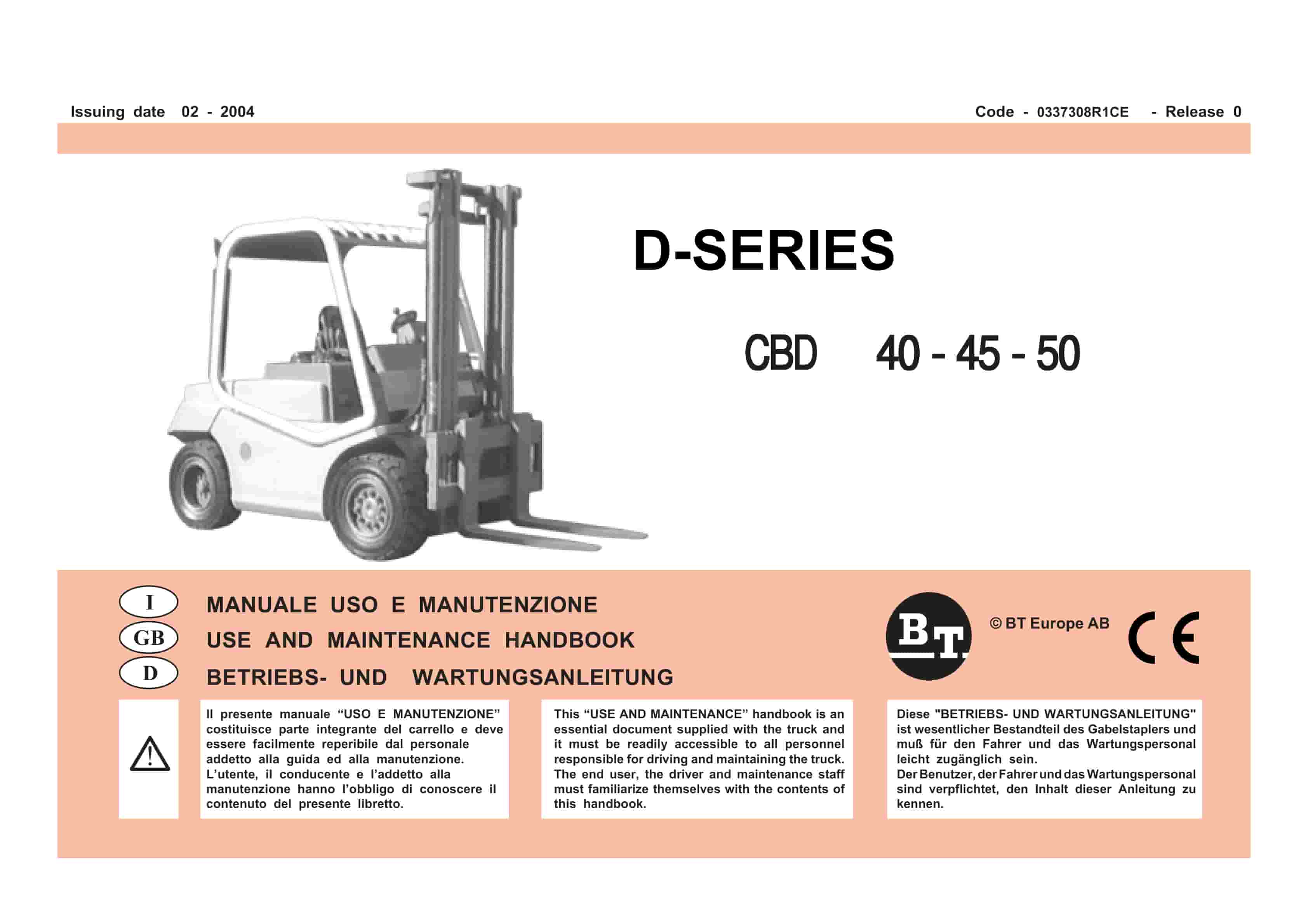
BT D-Series CBD40, CBD45, CBD50 Use And Maintenance Handbook 0337308R1CE
$30.00 Add to cart