



Bucyrus 25M Series Continuous Miner Operation Manual BI000727
$30.00
- Type Of Manual: Operation Manual
- Manual ID: BI000727
- Number of Pages: 151
- Size: 4.7MB
- Format: PDF
Product details
-
Model List:
- 25M Series Continuous Miner
- 1. About This Manual
- 1.1. Right Operating Manual
- 1.2. New Operating Manual
- 1.3. Efficiency
- 1.4. Service
- 2. Your Safety
- 2.1. State of the Art
- 2.2. Further Operating Manuals
- 2.3. Safety Precautions
- 2.4. Training
- 2.5. Operating Conditions
- 2.6. Storage and transport
- 2.7. Pre-Start Inspection
- 2.8. Operation
- 2.9. Inspection
- 2.10. Maintenance
- 2.11. Instruction and Safety
- 2.12. Operators Compartment
- 2.13. Stopping
- 2.14. Operators Compartment
- 2.15. Parking
- 2.16. Securing
- 2.17. Replacing Components
- 2.18. Original Parts
- 2.19. Lifting
- 2.20. Handling Hydraulic Fluids
- 2.21. Permissible Hoses
- 3. Storage and Transport
- 3.1. Corrosion Protection
- 3.2. No Direct Exposure to Sunlight
- 3.3. Short Term Storage
- 3.4. Long Term Storage
- 3.5. Plastic Deformation
- 3.6. Random Sample Inspection
- 3.7. Natural Aging
- 3.8. HFA Fluids
- 3.9. Before Transport
- 3.10. Temperature Below Freezing
- 3.11. Antifreeze Measures for Oil Cooler
- 3.12. Electrical and Electronic Components
- 4. Installation
- 4.1. Special Tools
- 4.2. General Safety Rules
- 4.3. General Safety Maintenance
- 4.4. Lubricate Every Shift
- 4.5. Inspect Daily
- 4.6. Lubricate Weekly
- 4.7. Lubricate Daily
- 4.8. Check Daily
- 4.9. Replace When Necessary
- 4.10. Electric Motor Maintenance
- 4.11. Every Month
- 4.12. Electric Motor Maintenance
- 4.13. Every Three Months
- 4.14. Every Six Months
- 4.15. Annually
- 4.16. Notes on Installation
- 4.17. Installation Plan
- 4.18. Supper Bolt Installation Specifications
- 4.19. Tightening Procedures
- 4.20. Loosening Procedures
- 4.21. Lubicants
- 4.22. Safety Features
- 4.23. Panic Strip (s)
- 4.24. Fire Suppression
- 4.25. Guards and Covers
- 4.26. Circuit Breaker Reset
- 5. Operation
- 5.1. Cutting Head Assembly
- 5.1.1. Cutting Support Frame Pivot Pin
- 5.1.2. Drum Drive Torque Limiting Switch
- 5.1.3. Drum Drive Motor 25M0 25M1
- 5.1.4. Drum Drive Motor 25M2 25M3
- 5.1.5. Shear Cylinder 25M0, 25M1 25M2
- 5.1.6. Shear Cylinder 25M3
- 5.1.7. Cutting Drum Installation Removal
- 5.1.7.1. Center Cutting Drums
- 5.1.7.2. End Cutting Drums
- 5.1.7.3. Main Cutting Drums
- 5.1.8. Cutting Drum Installation Removal
- 5.1.8.1. Center Cutting Drum
- 5.1.8.2. End Cutting Drum
- 5.1.8.3. Main Cutting Drum
- 5.1.9. Cutting Drum Installation Removal
- 5.1.9.1. End Cutting Drum
- 5.1.9.2. Center Cutting Drum
- 5.1.9.3. End Cutting Drum
- 5.1.10. Drum Drive Gear Case Installation / Removal
- 5.1.10.1. Figure 21 / 25M0
- 5.1.11. Drum Drive Gear Case Installation / Removal
- 5.1.11.1. Figure 22 / 25M1
- 5.1.12. Drum Drive Gear Case Installation / Removal
- 5.1.12.1. Figure 23 / 25M2 / 25M3
- 5.2. Gathering Head Assembly Installation / Removal
- 5.2.1. CLA Installation / Removal
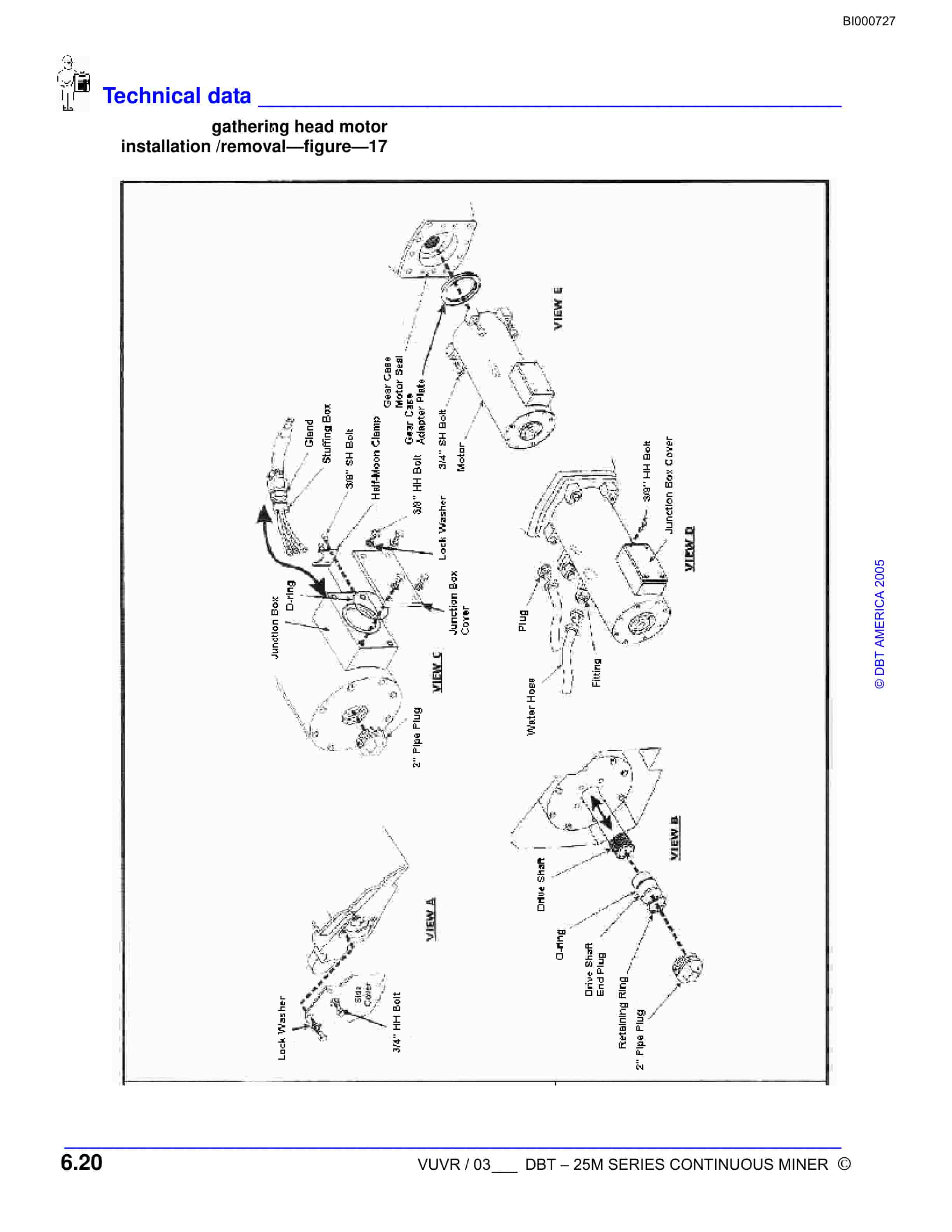
- 5.2.2. Gathering Head Motor Installation / Removal
- 5.2.3. Foot Shaft Installation / Removal
- 5.2.4. Gear Case Installation / Removal
- 5.2.5. Lift Cylinder Installation / Removal
- 5.3. Tram Case Installation / Removal From Tractor Frame
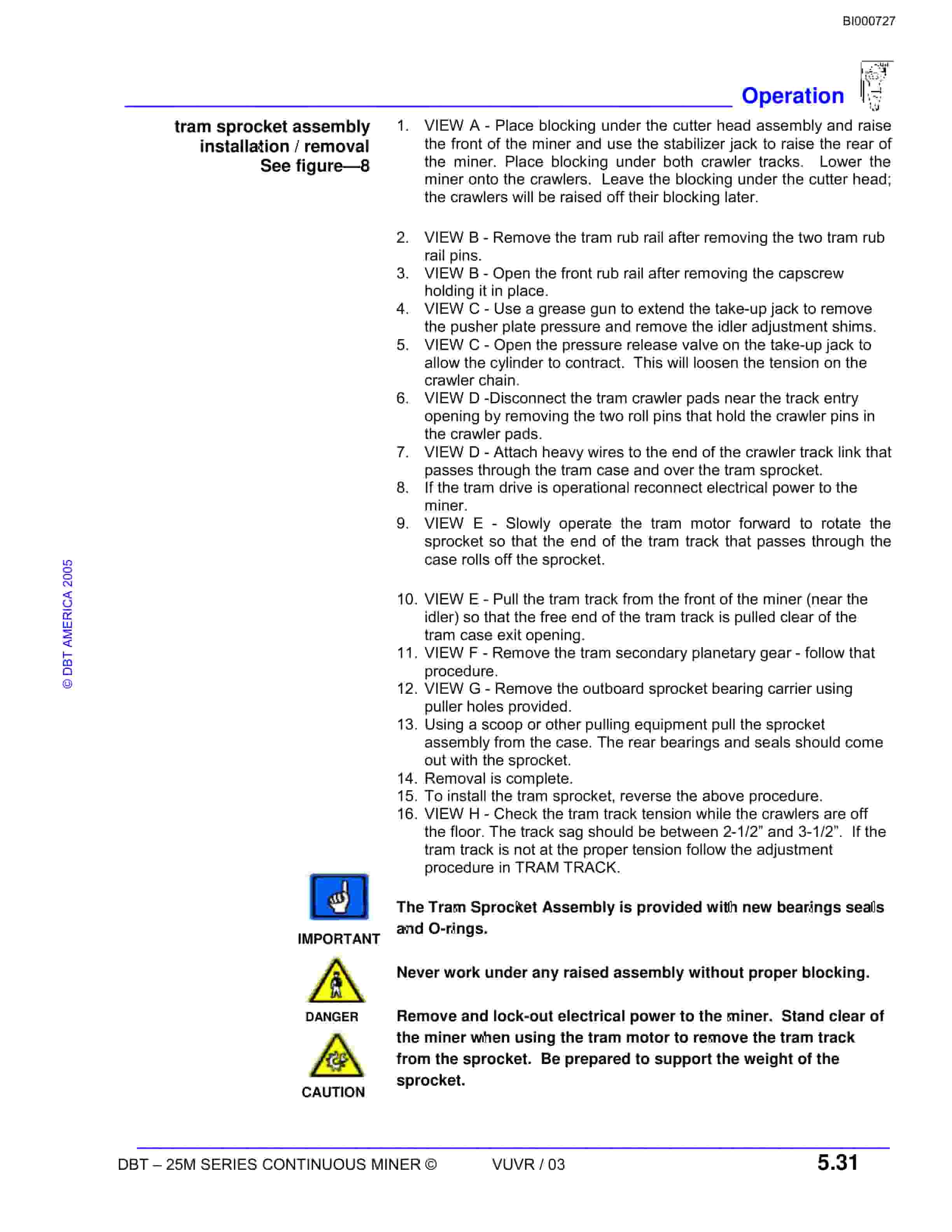
- 5.3.1. Tram Sprocket Installation / Removal
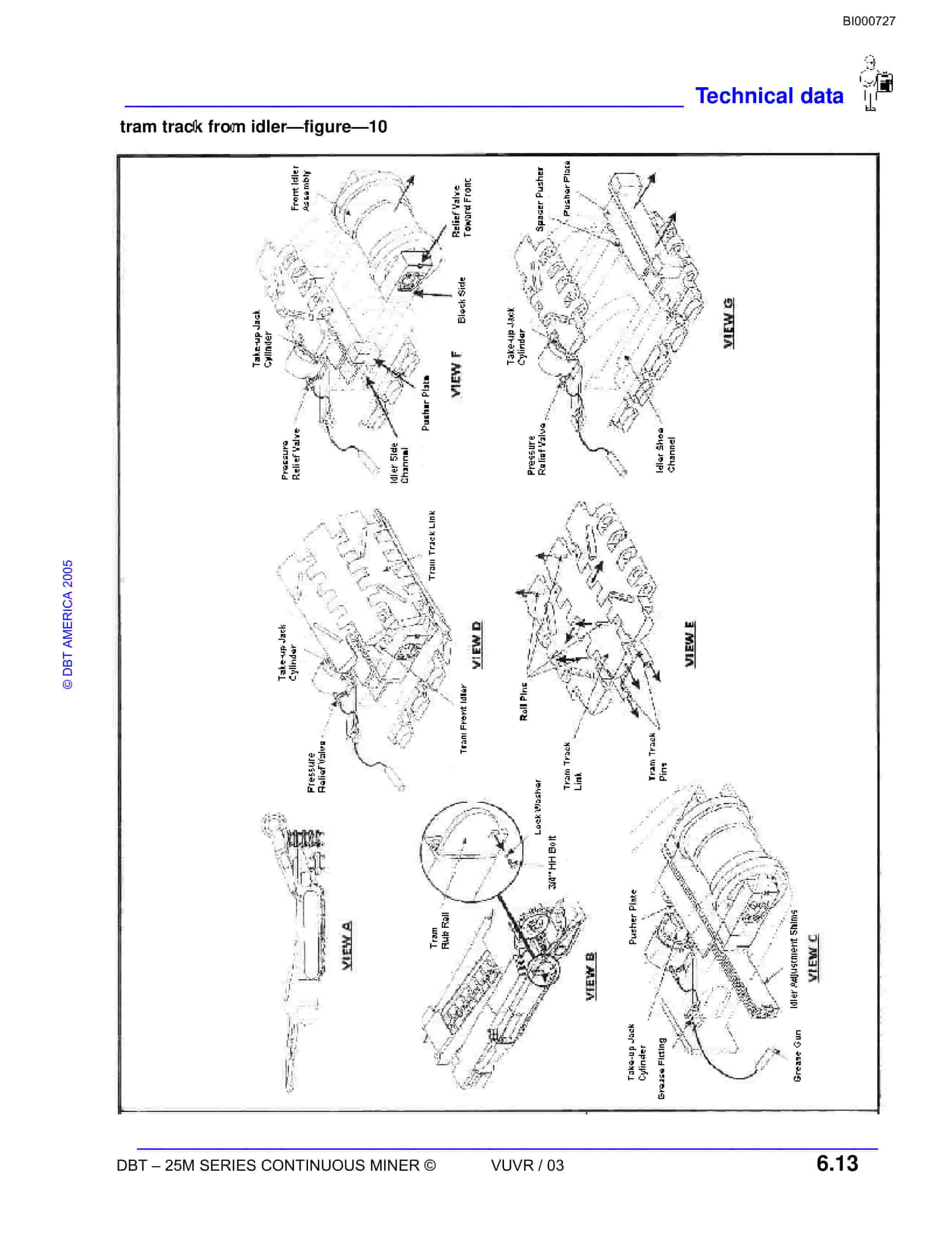
- 5.3.2. Crawler Front Idler Installation / Removal
- 5.3.3. Crawler Chain Tension Adjustment
- 5.3.4. Crawler Chain Take-Up Jack Assembly
- 5.3.5. Tram Planetary Installation / Removal
- 5.3.6. Tram Secondary Planetary Installation / Removal
- 5.3.7. Tram Case Installation / Removal
- 5.4. Stabilizing Cylinder Installation / Removal
- 5.5. Hydraulic Pump Installation / Removal
- 5.6. Hydraulic Pump Motor Installation / Removal
- 5.7. Conveyor Assembly Installation / Removal
- 5.7.1. Conveyor Lift Cylinder Installation / Removal
- 5.7.2. Tail Conveyor Shim Adjustment
- 5.7.3. Tail Roller Installation / Removal
- 5.7.4. Conveyor Swivel Pin Installation / Removal
- 5.7.5. Swing Cylinder Installation / Removal
- 5.7.6. Conveyor Chain Installation / Removal
- 5.7.7. Conveyor Chain Tension Adjustment
- 5.8. Scrubber System
- 5.8.1. Scrubber Motor
- 5.8.2. Scrubber Cleaning
- 5.9. Electrical Components
- 5.9.1. Power Schematic
- 5.9.2. Motor Overloads
- 5.9.3. Motor Control
- 5.9.4. Cutting Motor Feedback
- 5.9.5. Radio Control Schematic
- 5.9.6. Tram Dead Man Switch
- 5.9.7. Methane Monitor
- 5.9.8. Low Oil Level Switch
- 5.9.9. E-Stop Bypass
- 5.9.10. Battery Back-Up System
- 5.9.11. Scrubber Fan
- 5.9.12. Cutting Motor Feedback Adjustment
- 5.9.13. Armature Voltage
- 5.9.14. Radio Remote Control
- 5.9.15. Receiver, Power Supply Tram Case Module
- 5.9.16. Diagnostic Display
- 5.9.17. Radio Transmitter
- 5.9.18. Batery Charger
- 5.9.19. Permissibility
- 5.9.20. Trouble Shooting
- 5.9.21. Dual Systems
- 5.9.22. Diagnostic Display
- 5.9.23. Component Change Out
- 6. Technical Data
- 6.1. Tractor Frame (Figure 1)
- 6.2. Tram Motor (Figure 2)
- 6.3. Tram In-Put Planetary (Figure 3)
- 6.4. Tram Secondary Planetary (Figure 4)
- 6.5. Tram Case (Figure 5)
- 6.6. Tram Case (Figure 6)
- 6.7. Stabilizing Cylinder (Figure 7)
- 6.8. Tram Sprocket (Figure 8)
- 6.9. Crawler Chain Adjustment (Figure 9)
- 6.10. Crawler Front Idler (Figure 10)
- 6.11. Crawler Take-Up Jack (Figure 11)
- 6.12. Hydraulic Pump (Figure 12)
- 6.13. Hydraulic Pump Motor (Figure 13)
- 6.14. Gathering Head (Figure 14)
- 6.15. Gathering Head Assembly (Figure 15)
- 6.16. Gathering Head CLA Installation / Removal (Figure 16)
- 6.17. Gathering Head Motor Installation / Removal (Figure 17)
- 6.18. Gathering Head Foot Shaft Installation / Removal (Figure 18)
- 6.19. Foot Shaft Assembly (Figure 19)
- 6.20. Gathering Head Gear Case Installation / Removal (Figure 20)
- 6.21. Gathering Head Gear Case Assembly (Figure 21)
- 6.22. Gathering Head Gear CaseAssembly (Figure 22)
- 6.23. Gathering Head Lift Cylinder Installation / Removal (Figure 23)
- 6.24. Cutting Head Assembly (Figure 24)
- 6.25. Cutting Head Support Frame Assembly (Figure 25)
- 6.26. Cutting Head Pivot Pin 25M0 / 1 / 2 (Figure 26)
- 6.27. Cutting Head Pivot Pin 25M3 (Figure 27)
- 6.28. Cutting Head Torque Limiting Clutch 25M2 25M3 (Figure 28)
- 6.29. Cutting Head Motor 25M2 25M3 (Figure 29)
- 6.30. Cutting Head Motor 25M0 25M1 (Figure 30)
- 6.31. Cutting Head Shear Jack 25M0, 25M1 25M2 (Figure 32)
- 6.32. Cutting Head Shear Jack 25M3 (Figure 33)
- 6.33. Drum Drive Gear Case 25M0 (Figure 34)
- 6.34. Drum Drive Gear Case 25M1 (Figure 35)
- 6.35. Drum Drive Gear Case 25M2 (Figure 36)
- 6.36. Drum Drive Gear Case 25M3 (Figure 37)
- 6.37. Conveyor (Figure 38)
- 6.38. Conveyor (Figure 39)
- 6.39. Swing Cylinder (Figure 40)
- 6.40. Conveyor Swivel Pin (Figure 41)
- 6.41. Conveyor Tail Roller (Figure 42)
- 6.42. Tail Conveyor Shim Set (Figure 43)
Related products
-

Bucyrus 1570W Dragline Technical Manual BI005401
$30.00 Add to cart -

Bucyrus 1028 Miner Technical Manual BI000464
$30.00 Add to cart -

Bucyrus 1570W Technical Manual BI005404
$30.00 Add to cart -

Bucyrus 1370W Walking Dragline Technical Manual BI005573
$30.00 Add to cart -

Bucyrus 1260-W Walking Dragline Technical Manual BI005074
$30.00 Add to cart


