

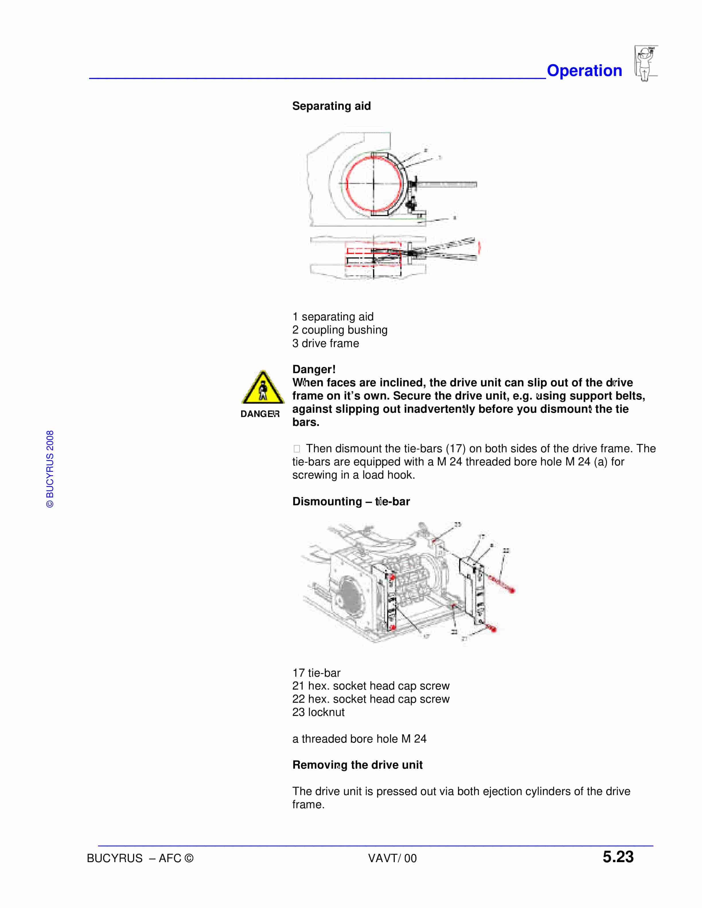
Bucyrus AFC PF-6 – 1342 Armored Face Conveyor Operation Manual
$30.00
- Type Of Manual: Operation Manual
- Number of Pages: 130
- Size: 3.3MB
- Format: PDF
Product details
-
Model List:
- AFC PF-6 – 1342 Armored Face Conveyor
- 1. ABOUT THIS MANUAL…………………………………………………………………………….. 1.0
- 2. about this manual ……………………………………………………………………………. 1.3
- 3. before starting work …………………………………………………………………………. 1.3
- 4. new operating manual ……………………………………………………………………… 1.3
- 5. purpose of operating manual …………………………………………………………….. 1.4
- 6. efficiency………………………………………………………………………………………… 1.4
- 7. service …………………………………………………………………………………………… 1.4
- 8. safety…………………………………………………………………………………………….. 1.4
- 9. characters and symbols……………………………………………………………………. 1.4
- 10. YOUR SAFETY………………………………………………………………………………………… 2.0
- 11. your safety ……………………………………………………………………………………… 2.3
- 12. state of the art…………………………………………………………………………………. 2.3
- 13. further operating manuals…………………………………………………………………. 2.3
- 14. installation and repair……………………………………………………………………….. 2.4
- 15. operating conditions…………………………………………………………………………. 2.5
- 16. intended use …………………………………………………………………………………… 2.5
- 17. prerequisites for operation………………………………………………………………… 2.6
- 18. safety instructions……………………………………………………………………………. 2.7
- 19. general…………………………………………………………………………………………… 2.7
- 20. noise emission………………………………………………………………………………… 2.7
- 21. protective equipment ……………………………………………………………………….. 2.7
- 22. symbol plates………………………………………………………………………………….. 2.7
- 23. emergency stop ………………………………………………………………………………. 2.7
- 24. lock out ………………………………………………………………………………………….. 2.7
- 25. cordon off working area ……………………………………………………………………. 2.7
- 26. ignition hazard ………………………………………………………………………………… 2.8
- 27. transport safety device……………………………………………………………………… 2.8
- 28. means of attachment ……………………………………………………………………….. 2.8
- 29. mobile handling system ……………………………………………………………………. 2.8
- 30. environmental acceptability ………………………………………………………………. 2.8
- 31. securing…………………………………………………………………………………………. 2.9
- 32. replacing components………………………………………………………………………. 2.9
- 33. original parts …………………………………………………………………………………… 2.10
- 34. protective devices……………………………………………………………………………. 2.10
- 35. handling of hydraulic fluids ……………………………………………………………….. 2.10
- 36. protective equipment hydraulic ………………………………………………………….. 2.10
- 37. maintenance and repair …………………………………………………………………… 2.10
- 38. pressure relief valves……………………………………………………………………….. 2.10
- 39. permissible hoses……………………………………………………………………………. 2.11
- 40. laying hydraulic hoses ……………………………………………………………………… 2.12
- 41. overview of the safety instructions……………………………………………………… 2.14
- 42. STORAGE AND TRANSPORT…………………………………………………………………… 3.0
- 43. corrosion protection …………………………………………………………………………. 3.3
- 44. no direct exposure to sunlight……………………………………………………………. 3.3
- 45. moisture and dirt……………………………………………………………………………… 3.3
- 46. short-term storage …………………………………………………………………………… 3.3
- 47. long-term storage…………………………………………………………………………….. 3.3
- 48. natural aging…………………………………………………………………………………… 3.3
- 49. transport ………………………………………………………………………………………… 3.4
- 50. temperatures below freezing …………………………………………………………….. 3.4
- 51. electrical and electronic components………………………………………………….. 3.4
- 52. machine parts …………………………………………………………………………………. 3.4
- 53. pan grippers……………………………………………………………………………………. 3.5
- 54. INSTALLATION ……………………………………………………………………………………….. 4.0
- 55. points to observe prior to installation ………………………………………………….. 4.3
- 56. which tools are required for installation……………………………………………….. 4.3
- 57. shutdown procedure ………………………………………………………………………… 4.4
- 58. notes on installation…………………………………………………………………………. 4.4
- 59. overview of the impact roll crusher drive unit……………………………………….. 4.5
- 60. main components and weights ………………………………………………………….. 4.6
- 61. assembling tensionable drive frame and drive……………………………………… 4.7
- 62. flushing system……………………………………………………………………………….. 4.8
- 63. hydraulic control system on the SPR3………………………………………………… 4.9
- 64. hydraulic control unit (image)…………………………………………………………….. 4.9
- 65. line and circuit diagram on the SPR3 (images)…………………………………….. 4.10
- 66. cover for the SPR3 (image) ………………………………………………………………. 4.11
- 67. discharge box (image) ……………………………………………………………………… 4.12
- 68. flange plate (image)…………………………………………………………………………. 4.13
- 69. instructions for installation of the gear box…………………………………………… 4.14
- 70. drive connection assembly (image) ……………………………………………………. 4.15
- 71. flange position “W”…………………………………………………………………………… 4.16
- 72. how to install the conveyor pans (image)…………………………………………….. 4.17
- 73. pan line—return head/crusher (image) ……………………………………………….. 4.18
- 74. pan line—crusher/tensionable drive frame SPR3 (image)……………………… 4.19
- 75. conveyor pans in the overlapping area (image)……………………………………. 4.20
- 76. stageloader pan (image)…………………………………………………………………… 4.21
- 77. convex pan (image) …………………………………………………………………………. 4.22
- 78. stageloader pan (image)…………………………………………………………………… 4.23
- 79. adaptor pan connecting to the SPR3 (image)………………………………………. 4.24
- 80. pan connection (image) ……………………………………………………………………. 4.25
- 81. anchor dog bone connection on the return assembly (image) ………………… 4.26
- 82. clamping bolt connection M72 in the overlapping area (image)………………. 4.27
- 83. connecting pans by clamping bolts…………………………………………………….. 4.27
- 84. tensioning the screw bolt (image) ………………………………………………………. 4.28
- 85. space between wedges (image) ………………………………………………………… 4.28
- 86. clamping bolt—fitted (image) …………………………………………………………….. 4.29
- 87. tightening the screw connections of the clamp wedges (image)……………… 4.29
- 88. screw bolt connection on the SPR3 (image)………………………………………… 4.30
- 89. accessories (generic)……………………………………………………………………….. 4.31
- 90. cable bracket (generic) …………………………………………………………………….. 4.31
- 91. entry spraying system………………………………………………………………………. 4.34
- 92. skizze—basic arrangement of spray system (sketch)……………………………. 4.34
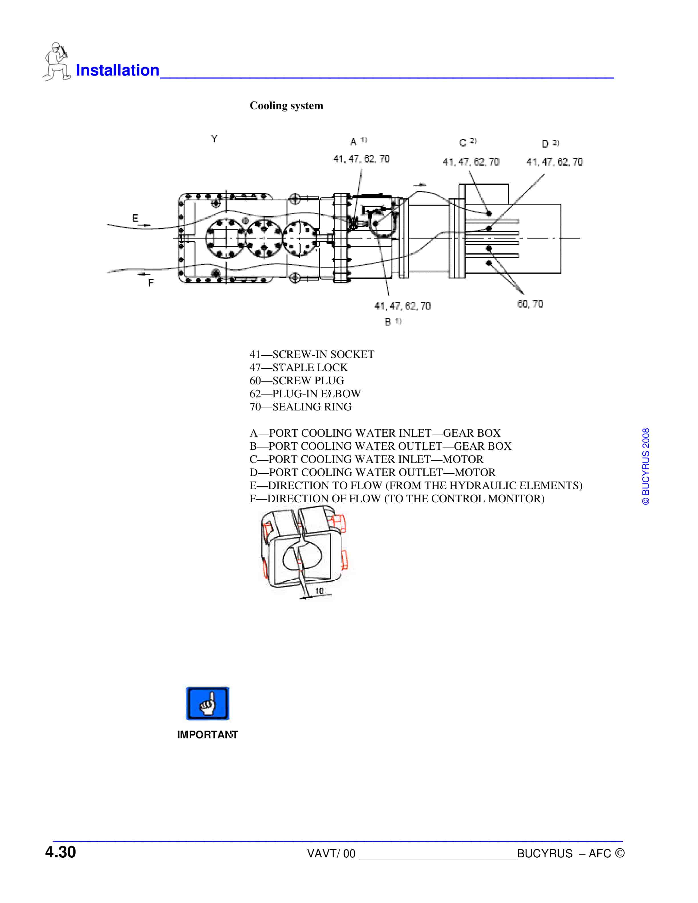
- 93. cooling system (image)…………………………………………………………………….. 4.35
- 94. how to assembly the chain (image) ……………………………………………………. 4.37
- 95. adjusting chains………………………………………………………………………………. 4.38
- 96. installing the chain connector ……………………………………………………………. 4.38
- 97. opening the block type connector ………………………………………………………. 4.39
- 98. closing the block type connector………………………………………………………… 4.39
- 99. dimensions of different flat type connectors…………………………………………. 4.40
- 100. how to tension the chain assembly…………………………………………………….. 4.40
- 101. necessary tensioning force ……………………………………………………………….. 4.40
- 102. correct pre-tension…………………………………………………………………………… 4.40
- 103. too much slack………………………………………………………………………………… 4.41
- 104. excessive chain pre-tension ……………………………………………………………… 4.41
- 105. changes in chain pre-tension during operation …………………………………….. 4.41
- 106. monitoring the chain assembly ………………………………………………………….. 4.41
- 107. how to tension the conveyor chain……………………………………………………… 4.41
- 108. fitting the chain locking device (image)……………………………………………….. 4.42
- 109. securing the center section with pins (image)………………………………………. 4.43
- 110. sequencing control of the conveyor ……………………………………………………. 4.44
- 111. starting…………………………………………………………………………………………… 4.45
- 112. stopping…………………………………………………………………………………………. 4.45
- 113. how to start-up conveyor system ……………………………………………………….. 4.45
- 114. test run the conveyor ……………………………………………………………………….. 4.46
- 115. after the test run………………………………………………………………………………. 4.47
- 116. test operation of the loaded conveyor…………………………………………………. 4.48
- 117. after the test operation……………………………………………………………………… 4.48
- 118. releasing the conveyor……………………………………………………………………… 4.48
- 119. how to dismantle and withdraw the conveyor system……………………………. 4.49
- 120. draw up dismantling plan………………………………………………………………….. 4.49
- 121. handling delicate components …………………………………………………………… 4.49
- 122. OPERATION……………………………………………………………………………………………. 5.0
- 123. operation………………………………………………………………………………………… 5.3
- 124. who is allowed to operate the conveyor………………………………………………. 5.3
- 125. when may conveyor be started………………………………………………………….. 5.3
- 126. how to operate the drive frame SPR3…………………………………………………. 5.3
- 127. hydraulic control unit on the SPR3……………………………………………………… 5.3
- 128. mechanical lockout of the tensionable drive frame ……………………………….. 5.4
- 129. instructions on the maintenance of the conveyor………………………………….. 5.5
- 130. shearer mechanical stop…………………………………………………………………… 5.5
- 131. lubrication schedule…………………………………………………………………………. 5.6
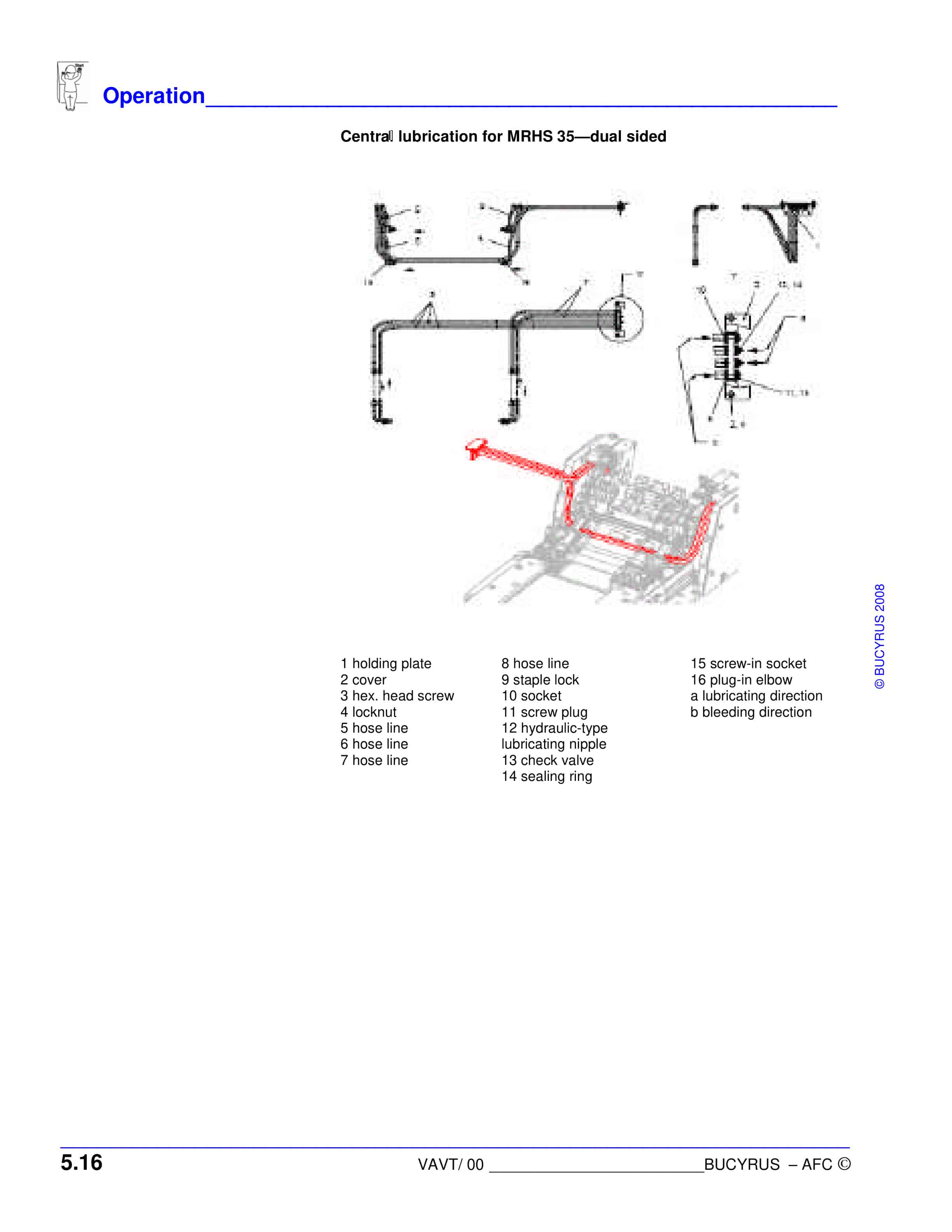
- 132. central lubrication system (image) ……………………………………………………… 5.6
- 133. lubricating points (image)………………………………………………………………….. 5.7
- 134. inspection of the system …………………………………………………………………… 5.7
- 135. weekly………………………………………………………………………………….. 5.7
- 136. monthly ………………………………………………………………………………… 5.7
- 137. instructions on the maintenance of the hydraulic system……………………….. 5.8
- 138. maintenance of the hydraulic system………………………………………………….. 5.8
- 139. daily …………………………………………………………………………………….. 5.8
- 140. weekly………………………………………………………………………………….. 5.8
- 141. instructions on the replacement of wear parts ……………………………………… 5.9
- 142. sprocket drum…………………………………………………………………………………. 5.9
- 143. assembly ……………………………………………………………………………………….. 5.9
- 144. tappet…………………………………………………………………………………………….. 5.9
- 145. chain sprocket bolt…………………………………………………………………………… 5.10
- 146. tightening torque……………………………………………………………………………… 5.10
- 147. chain sprocket (image) …………………………………………………………………….. 5.10
- 148. chain stripper (image)………………………………………………………………………. 5.11
- 149. guides in concave pan (image)………………………………………………………….. 5.12
- 150. TECHNICAL DATA…………………………………………………………………………………… 6.0
- 151. technical data …………………………………………………………………………………. 6.3
- 152. permissible power ratings …………………………………………………………………. 6.4
- 153. marking of the tensionable drive frame……………………………………………….. 6.5
- 154. tightening torques ……………………………………………………………………………. 6.6
- 155. permissible media……………………………………………………………………………. 6.7
- 156. stability test…………………………………………………………………………………….. 6.7
- 157. certificate ……………………………………………………………………………………….. 6.9
- 158. hydraulic fluid maintenance ………………………………………………………………. 6.10
- 159. quality of the process water ………………………………………………………………. 6.10
- 160. lubricating greases and pastes ………………………………………………………….. 6.11
- 161. FOR YOUR INFORMATION ………………………………………………………………………. 7.0
- 162. our service ……………………………………………………………………………………… 7.3
Related products
-

Bucyrus 151-M Shovel And Dragline Technical Manual BI005702
$30.00 Add to cart -

Bucyrus 151-M Shovel And Dragline Technical Manual BI006254
$30.00 Add to cart -

Bucyrus 1570W Dragline Technical Manual BI005401
$30.00 Add to cart -
Bucyrus 1140V FLP Starter Operation Manual
$30.00 Add to cart -

Bucyrus 151-M Technical Manual BI005612
$30.00 Add to cart


