

Caterpillar EL2000 Shearer Operation And Maintenance Manual BI001780-00-00-EN-CMPL
$30.00
- Type Of Manual: Operation And Maintenance Manual
- Manual ID: BI001780-00-00-EN-CMPL
- Number of Pages: 356
- Size: 9.2MB
- Format: PDF
Product details
-
Model List:
- EL2000 Shearer
- 1. EL2000-014 Electra 2000
- 1.1. Contents
- 1.2. About this manual
- 1.2.1. Before starting work
- 1.2.2. Who is this operating manual for
- 1.2.3. Characters and symbols used
- 1.3. Your safety
- 1.3.1. Your safety
- 1.3.2. Observe the safety accident prevention rules
- 1.3.3. Personnel
- 1.3.4. Operating conditions
- 1.3.5. Unauthorised use
- 1.3.6. Safety instructions
- 1.3.7. Storage and transport
- 1.3.8. To electrically isolate the shearer
- 1.3.9. Overview of safety instructions
- 1.4. Storage and transport
- 1.4.1. Storage
- 1.4.2. Transport
- 1.4.3. Unit weights
- 1.4.4. Cutting drum removal
- 1.4.5. Ranging arm hydraulic cylinder removal
- 1.4.6. EL68A Ranging arm motor removal
- 1.4.7. RA750 Ranging arm removal
- 1.4.8. EL53A Haulage downdrive removal
- 1.4.9. EL55A Haulage motor removal
- 1.4.10. EL57B Haulage unit removal
- 1.4.11. EL56BN Hydraulic power pack motor removal
- 1.4.12. Hydraulic reservoir removal
- 1.4.13. EL49A Control box EL48A power box removal
- 1.4.14. EL45A Mainframe
- 1.4.15. Face side skid shoe removal
- 1.5. Installation
- 1.5.1. Installation of machine underground
- 1.5.2. Greasing
- 1.5.3. Oil and fluid filling
- 1.5.4. Commissioning the haulage system
- 1.5.5. Fault diagnosis and repair
- 1.6. Operation
- 1.6.1. Introduction to electrical equipment
- 1.6.1.1. General
- 1.6.1.2. Electrical control boxes
- 1.6.1.3. Electric motor driven units
- 1.6.1.4. Hydraulic actuated units
- 1.6.1.5. Other electrical equipment
- 1.6.1.6. Electrical circuits
- 1.6.2. EL49A Control box
- 1.6.2.1. General
- 1.6.2.2. Unit contents
- 1.6.3. EL48A Power box
- 1.6.3.1. General
- 1.6.3.2. Component location
- 1.6.4. Operator controls (electrical)
- 1.6.4.1. Main switch handle
- 1.6.4.2. Machine START pushbutton
- 1.6.4.3. Motors START / STOP pushbutton
- 1.6.4.4. Motor STOP pushbutton
- 1.6.4.5. Control circuit earth leakage test pushbutton
- 1.6.4.6. Haulage circuit earth leakage test pushbutton
- 1.6.4.7. Earth leakage circuits reset pushbutton
- 1.6.4.8. Stop/emergency stop lever
- 1.6.4.9. Radio control selection
- 1.6.4.10. Haulage system circuit breaker handle
- 1.6.5. Electrical pilot circuit
- 1.6.5.1. General
- 1.6.5.2. Pilot circuit
- 1.6.6. Electrical power distribution
- 1.6.6.1. General
- 1.6.6.2. Main power distribution
- 1.6.6.3. Control power distribution
- 1.6.7. EL68A Ranging arm motor
- 1.6.7.1. General
- 1.6.7.2. System operation
- 1.6.7.3. Quill shaft removal procedures
- 1.6.7.4. Quill shaft lubrication
- 1.6.8. EL56BN Hydraulic power pack motor
- 1.6.8.1. General
- 1.6.8.2. System operation
- 1.6.8.3. Motor start circuit
- 1.6.8.4. Lubrication
- 1.6.9. EL55A Haulage motor
- 1.6.9.1. General
- 1.6.9.2. Motor operation
- 1.6.9.3. Motor start circuit
- 1.6.9.4. Motor removal procedure
- 1.6.9.5. Quill shaft removal and assembly
- 1.6.9.6. Lubrication
- 1.6.10. Pempek radio control system
- 1.6.10.1. General
- 1.6.10.2. Transceiver
- 1.6.11. Hydraulic functions (electric control)
- 1.6.11.1. General
- 1.6.12. Haulage system (AC drive)
- 1.6.12.1. General
- 1.6.12.2. Basic system operation
- 1.6.12.3. Haulage circuit description
- 1.6.12.4. Main circuit
- 1.6.12.5. Monitoring circuits
- 1.6.12.6. Radio control circuits
- 1.6.12.7. Transmitter control circuit
- 1.6.12.8. Double drive operation
- 1.6.12.9. Introduction to inverter drives
- 1.6.12.10. Drive configuration
- 1.6.12.11. Multiple drives and motors
- 1.6.12.12. Frequency slaving
- 1.6.12.13. Current slaving
- 1.6.12.14. Electrical paralleling
- 1.6.12.15. COMPACT display module and keypad
- 1.6.12.16. Configuration switches
- 1.6.12.17. Switch positions and modes
- 1.6.13. Component location (quick reference guide)
- 1.6.13.1. General
- 1.6.13.2. Electrical component location (general)
- 1.6.13.3. EL48A Left and right hand covers
- 1.6.13.4. EL48A Component location
- 1.6.13.5. EL49A Control cover
- 1.6.13.6. Control compartment chassis
- 1.6.14. Maintenance (electrical)
- 1.6.14.1. Maintenance schedules
- 1.6.15. Introduction to mechanical equipment
- 1.6.15.1. General machine specification
- 1.6.15.2. Abbreviations
- 1.6.16. Operator controls (mechanical electrical)
- 1.6.16.1. Electrical supply
- 1.6.16.2. Machine controls
- 1.6.16.3. Control mode selector switch
- 1.6.16.4. Cooling supply
- 1.6.16.5. Emergency stop switch and buttons
- 1.6.16.6. Face conditions
- 1.6.16.7. Stopping the shearer
- 1.6.16.8. Electrical trips
- 1.6.16.9. Shearer operators report
- 1.6.17. EL45A Mainframe
- 1.6.17.1. Waste side and plan
- 1.6.17.2. Face side view
- 1.6.17.3. Hinge pin arrangement
- 1.6.17.4. Ranging arm cylinder anchor
- 1.6.17.5. Face side skid shoe
- 1.6.17.6. Face side skid shoe wear limit
- 1.6.17.7. Ranging arm hinge points lubrication
- 1.6.18. EL57B Haulage unit
- 1.6.18.1. General
- 1.6.18.2. Haulage system location
- 1.6.18.3. Outside views
- 1.6.18.4. General arrangement
- 1.6.18.5. Encoder
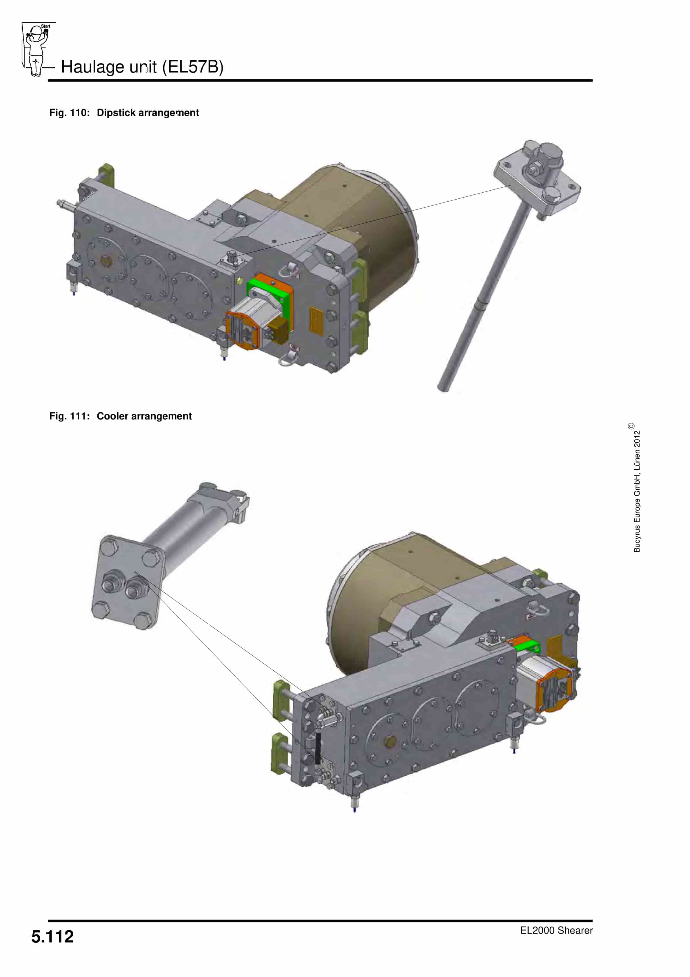
- 1.6.18.6. Dipstick
- 1.6.18.7. Cooler arrangement
- 1.6.18.8. Haulage unit lubrication
- 1.6.19. EL53A Downdrive
- 1.6.19.1. Downdrive system
- 1.6.19.2. Front and rear views
- 1.6.19.3. Component location
- 1.6.19.4. Trapping shoe wear limits
- 1.6.19.5. Drive quill shaft removal/assembly
- 1.6.19.6. Lubrication
- 1.6.20. RA750 Ranging arm
- 1.6.20.1. Introduction
- 1.6.20.2. General
- 1.6.20.3. High speed section
- 1.6.20.4. Drum speed
- 1.6.20.5. Coolers
- 1.6.20.6. Ranging arm lifting cylinder
- 1.6.20.7. Fit ranging arm to mainframe
- 1.6.20.8. Lubrication
- 1.6.21. Power pack EL50A hydraulic system
- 1.6.21.1. Introduction
- 1.6.21.2. General
- 1.6.21.3. Hydraulic reservoir
- 1.6.21.4. Hydraulic fluid cooling
- 1.6.21.5. Pressure filter
- 1.6.21.6. Return line filter
- 1.6.21.7. Safety relief valve
- 1.6.21.8. Hydraulic pump
- 1.6.21.9. Directional control valve bank
- 1.6.21.10. Ranging arm lifting cylinder
- 1.6.21.11. Cylinder valve block
- 1.6.21.12. Low pressure solenoid valve
- 1.6.21.13. Hydraulic system technical data
- 1.6.21.14. Hydraulic symbolic diagram
- 1.6.21.15. Lubrication
- 1.6.22. Water system
- 1.6.22.1. Introduction
- 1.6.22.2. Fire fighting
- 1.6.22.3. Reverse flush filter
- 1.6.22.4. Main water pilot valve
- 1.6.22.5. Dust suppression
- 1.6.22.6. Water circuit interlocking and monitoring
- 1.6.22.7. Pre-start warning / PBF circuit
- 1.6.22.8. Cooling system
- 1.6.22.9. Pressure reducing valve
- 1.6.22.10. Relief valve
- 1.6.22.11. Flow regulator assemblies
- 1.6.22.12. Ranging arm motor cooler
- 1.6.22.13. Ranging arm internal coolers
- 1.6.22.14. Haulage motor cooler
- 1.6.22.15. Haulage unit cooler
- 1.6.22.16. Power box cooling
- 1.6.22.17. Pump motor cooler
- 1.6.22.18. Hydraulic fluid cooler
- 1.6.22.19. Water symbolic diagram
- 1.6.23. Maintenance (mechanical)
- 1.6.23.1. Introduction
- 1.6.23.2. Oil and fluid condition monitoring
- 1.6.23.3. Maintenance schedules
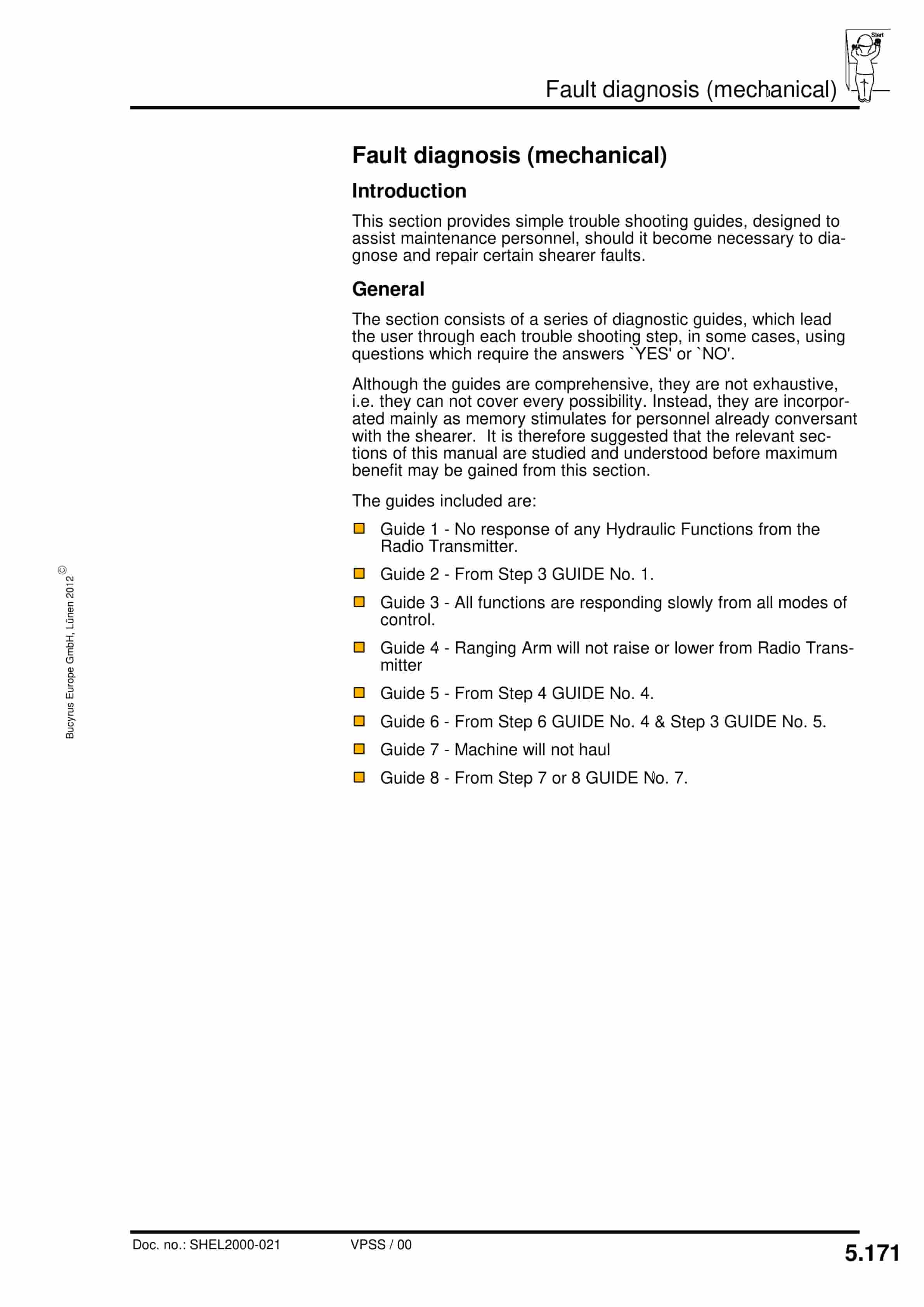
- 1.6.24. Fault diagnosis (mechanical)
- 1.6.24.1. Introduction
- 1.6.24.2. Guide 1
- 1.6.24.3. Guide 2
- 1.6.24.4. Guide 3
- 1.6.24.5. Guide 4
- 1.6.24.6. Guide 5
- 1.6.24.7. Guide 6
- 1.6.24.8. Guide 7
- 1.6.24.9. Guide 8
- 1.7. Technical data
- 1.7.1. Permissible media
- 1.7.1.1. Gear oil
- 1.7.1.2. Hydraulic fluid
- 1.7.1.3. Quill shaft grease
- 1.7.1.4. Electric motor bearing grease
- 1.7.1.5. All other grease applications
- 1.7.1.6. Lubricants chart
- 1.7.2. Tightening torques (coarse pitch)
- 1.7.2.1. Bolts grade 8.8 nuts grade 8
- 1.7.2.2. Bolts grade 10.9 nuts grade 12
- 1.7.3. Tightening torques (special applications only)
- 1.7.3.1. Bolts grade 12.9 nuts grade 12
- 1.7.4. Tightening torques (fine pitch)
- 1.7.4.1. Bolts and set screws grade 8.8
- 1.7.4.2. Bolts and set screws grade 10.9
- 1.7.4.3. Bolts and set screws grade 12.9
- 1.7.5. SUPERNUT tensioning system
- 1.7.6. Electrical diagrams
- 1.7.6.1. Diagram identification
- 1.7.6.2. Balloon mapping instructions
- 1.7.6.3. Relay mapping instructions
- 1.7.6.4. Wire number colour code
- 1.7.6.5. Wire numbering and colour coding
- 1.7.6.6. Standing instructions
- 1.7.6.7. Plug and socket details
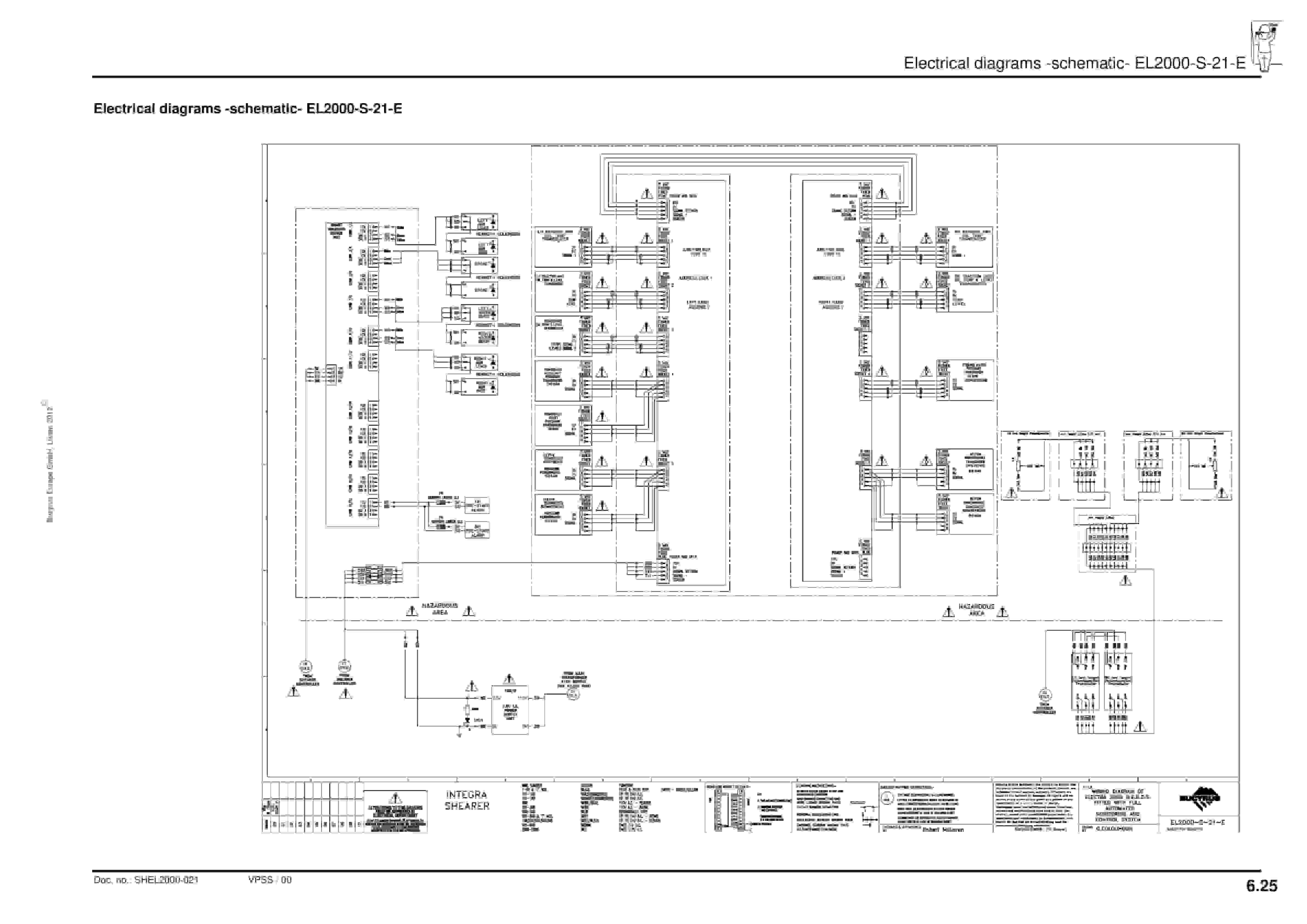
- 1.7.6.8. Electrical diagrams
- 1.8. For your information
- 1.8.1. Our service
- 1.8.2. Standards and guidelines
- 1.8.2.1. Hydraulic, Water and Lubrication diagrams
- 1.8.2.2. Supernut
- 1.8.2.3. P S Expansion bolt system
- 1.8.2.4. Clampex clamping set
- 1.8.2.5. Amercable trailing cable
- 1.8.2.6. Pempek radio system
- 1.8.2.7. Rocol dry moly paste
Related products
-
Caterpillar BUC-SCR 120 Series Battery Charger Operation And Maintenance Manual BI001952
$30.00 Add to cart -
Caterpillar CL115 Compact Loader Operation And Maintenance Manual A6474X384
$30.00 Add to cart -
Caterpillar CL115 Compact Loader MSHA Documentation A6474X387
$30.00 Add to cart -
Caterpillar CM345 Continuous Miner Operation And Maintenance Manual BI001591-02
$30.00 Add to cart -
Caterpillar BSL PF 6-1542 Operating Manual 0010 452 600 BA 00
$30.00 Add to cart


