

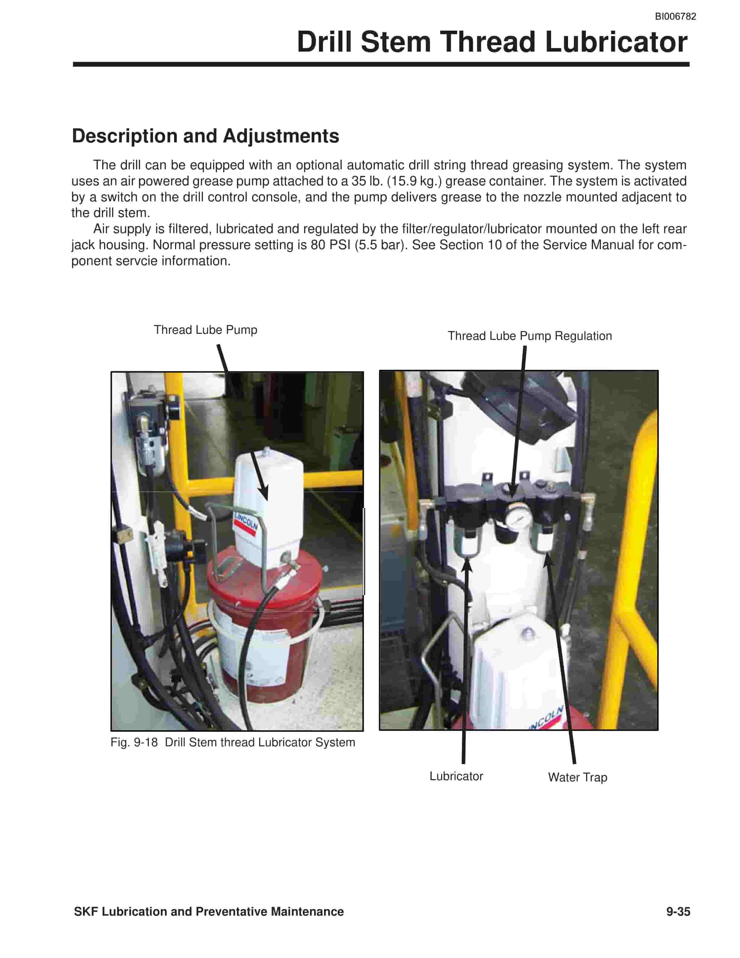
Caterpillar MD6240, MD6290 Rotary Blasthole Drill Service Manual BI006782
$30.00
- Type Of Manual: Service Manual
- Manual ID: BI006782
- Number of Pages: 1018
- Size: 144.6MB
- Format: PDF
Product details
-
Model List:
- MD6240, MD6290 Rotary Blasthole Drill
- 1. PARTS ORDERING AND PRODUCT SUPPORT
- 2. Safety Information
- 3. Safety Support Placement
- 4. Product Description
- 5. SKF Component Locator
- 6. SKFX Component Locator
- 7. Contents
- 8. Section 1 – Safety
- 8.1. Hazard Classification
- 8.2. Overview of Potential Hazards
- 8.3. Safety Guidelines
- 8.4. Safety Sign List
- 8.5. Safety Sign Locator
- 8.6. Safety Signs
- 9. Section 2 – Operator Controls
- 9.1. Graphic Symbol Legend
- 9.2. Operator Control Panel (standard)
- 9.3. Operator Control Panel (optional)
- 9.4. Cat EMS Panel
- 9.5. System Pressure Gauge Panel
- 9.6. Switch Panel (standard)
- 9.7. Lights, Circuit Breakers
- 9.8. Heater/AC Controls
- 9.9. AC/Heater
- 9.10. Operators Seat
- 10. Section 3 – Mainframe/Crawlers
- 10.1. Leveling Jacks
- 10.2. Mast Elevating Cylinders
- 10.3. Crawler Assembly
- 10.4. Metric Bolt Torque Specifications
- 10.5. Track Maintenance
- 10.6. Track Tension Adjustment
- 10.7. Track Chain
- 10.8. Track Shoes
- 10.9. Track Shoe Bolt Torque
- 10.10. Track Assembly
- 10.11. Final Drive
- 10.12. Idler Unit
- 10.13. Track Tension Unit
- 10.14. Track Rollers
- 10.15. Support Rollers
- 11. Section 4 – Drivetrain/Compressor
- 11.1. Engine and Drivetrain Service Procedures
- 11.2. Engine and Compressor Air Cleaners
- 11.3. Flexible Drive Coupling
- 11.4. Pump Drive
- 11.5. Hydraulic Pumps
- 11.6. Hydraulic Pump – Startup
- 11.7. Hydraulic Piston Pumps – Maintenance
- 11.8. Hydraulic Piston Pump – Troubleshooting
- 11.9. Engine Drivetrain Service Procedures
- 11.9.1. Hydraulic Gear Pumps – Removal Replacement
- 11.9.2. P330/P350/P365 Pump Manual
- 11.10. Compressor Service Procedures
- 11.10.1. Drive Coupling – Removal Replacement
- 11.10.2. Before Installation and Start-Up of New or Rebuilt Compressor
- 11.10.3. Compressor Unit (low pressure) – Installation
- 11.10.4. Compressor Unit (high pressure) – Installation
- 11.11. Main Auxiliary Air
- 11.11.1. Compressed Air Subsystem Components (low pressure)
- 11.11.2. Compressed Air Functions
- 11.11.3. Compressor Unit
- 11.11.4. Butterfly Inlet Control System (low pressure)
- 11.11.5. Butterfly Inlet Control System (high pressure)
- 11.11.6. Compressor Oil Filter Service Bulletin
- 11.11.7. Compressor Oil Filter
- 11.11.8. Sullair Low Pressure Manual
- 11.11.9. Sullair High Pressure Manual
- 11.12. Radiator/Oil Cooler Assembly
- 11.12.1. Double Fan Plumbing Circuit
- 11.12.2. Square Tube Installation Tools
- 11.12.3. Round Tube Installation Tool
- 11.12.4. Mesabi Radiators Cores Manuals
- 12. Section 5 – Dust Control Systems
- 12.1. System Functions
- 12.2. Dust Collector Basic Specifications
- 12.3. Initial Startup
- 12.4. Fan Speed Adjustment
- 12.5. Direction of Fan Rotation
- 12.6. Compressed Air Supply
- 12.7. Electric Timer
- 12.8. Filter Maintenance
- 12.9. Routine Maintenance
- 12.10. Troubleshooting Guide
- 12.11. Water Pump (vertical)
- 12.12. Dust Collector/Water Injection Circuit
- 12.13. Water Injection System (vertical pump)
- 12.14. Water Injection System (horizontal pump)
- 12.15. Cat Pumps Service Manual
- 12.16. Char-Lynn 2000 Series Hydraulic Motor Manual
- 13. Section 6 – Mast/Rotary Drive/Pipe Rack
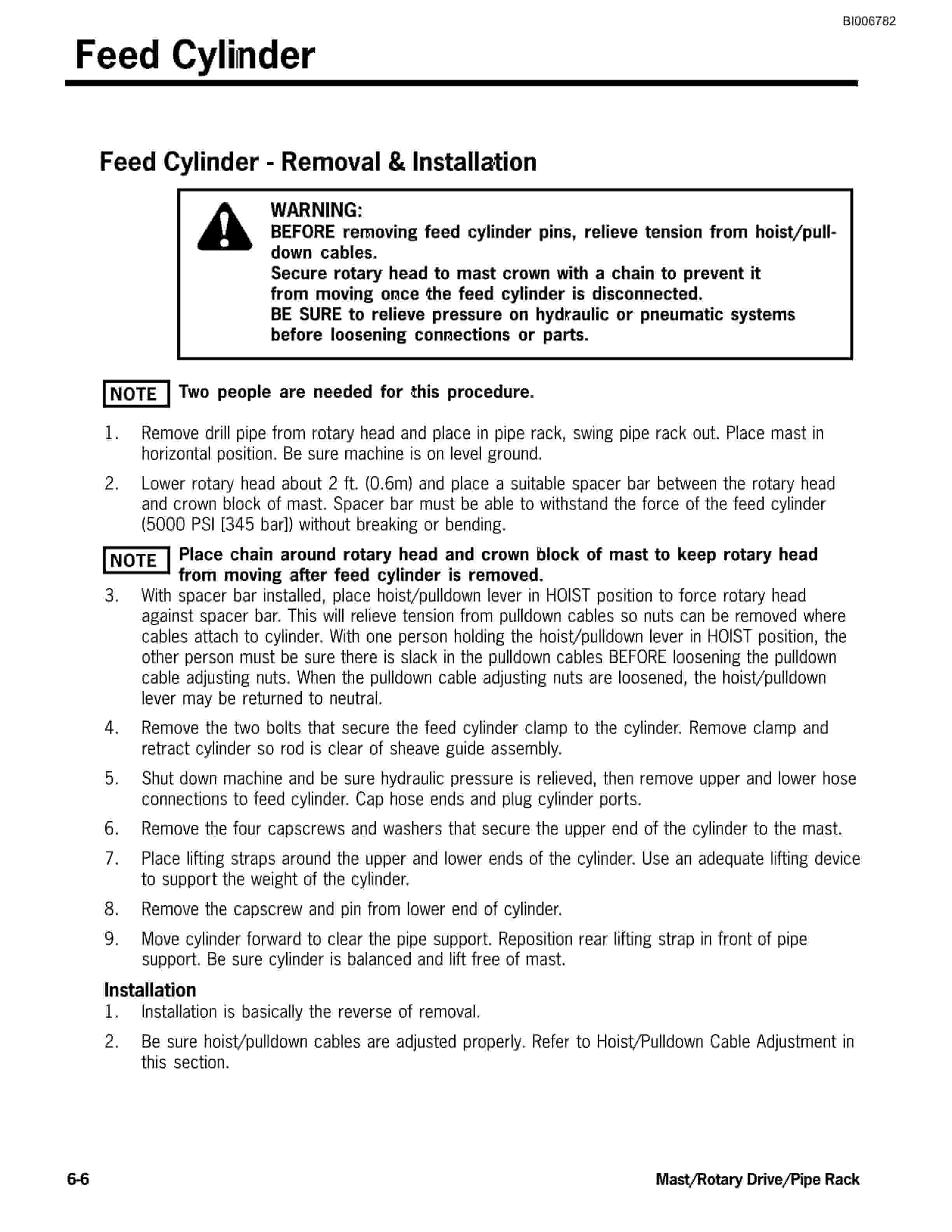
- 13.1. Feed Cylinder
- 13.2. Hoist/Pulldown Cable Adjustment
- 13.3. Hoist/Pulldown Cable Replacement
- 13.4. Rotary Head Guide Alignment
- 13.5. Rotary Drive Assembly
- 13.6. Rotary Drive Gearbox (early models)
- 13.7. Rotary Drive Gearbox (late models)
- 13.8. Rexroth AA6VM Hydraulic Motor Manual
- 13.9. Winch Assembly
- 13.9.1. Wire Rope
- 13.9.2. Wire Rope Clips
- 13.9.3. Wedge Sockets
- 13.9.4. Braden Winch Manual
- 13.10. HOBO Wrench
- 13.11. Carousel Pipe Rack
- 13.12. Char-Lynn 2000 Series Hydraulic Motor Manual
- 14. Section 7 – Hydraulic Systems
- 14.1. Hydraulic Tank
- 14.2. Pressure Setting Sequence
- 14.3. Hydraulic Pressure Test Circuit
- 14.4. Hydraulic Pump Identification
- 14.5. Right Track, Left Track/Rotation Pumps
- 14.6. Feed and Auxiliary Pump Circuit
- 14.7. Hydraulic Feed Circuit
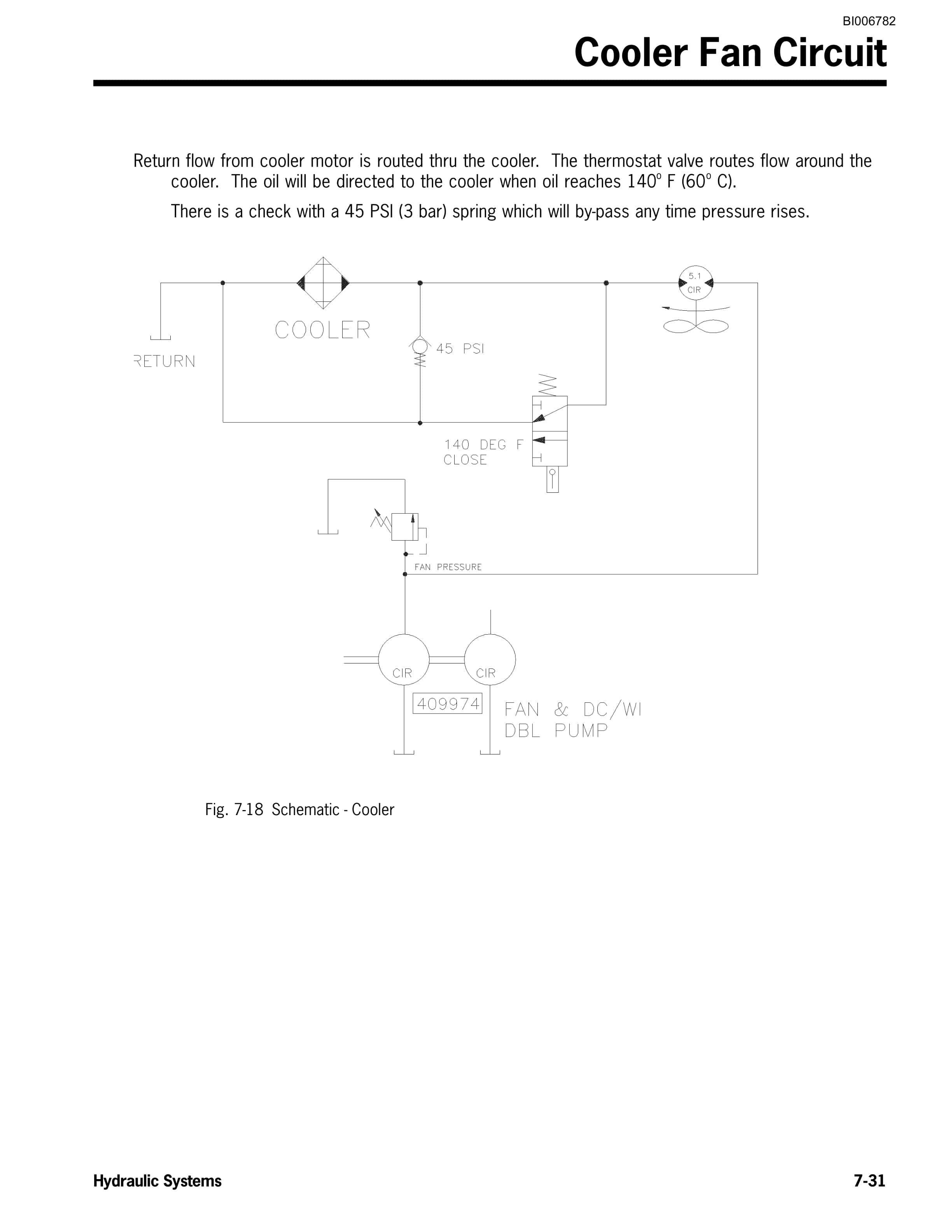
- 14.8. Cooler Fan Circuit
- 14.9. Jack and Mast Elevate Circuit
- 14.10. Leveling Jack Cylinders
- 14.11. Mast Elevating Cylinders
- 14.12. Drill/Tram Control Circuit
- 14.13. Joystick Adjustments (electric)
- 14.14. Auxiliary Functions Circuit
- 14.15. HOBO Wrench
- 14.16. Dust Curtain/Main Air Circuit
- 14.17. Rotary Drive Pulldown Tables
- 14.18. Counterbalance Valve Adjustment
- 14.19. Loop Filters
- 14.20. Charge Filters
- 14.21. Main Return and Case Drain Filters
- 14.22. Hydraulic Cylinder Repair
- 14.23. SKF Hydraulic Schematic
- 14.24. SKFX Hydraulic Schematic
- 14.25. Hydraulic Piping – SKF Cab Controls
- 14.26. Rotary Torque Control
- 15. Section 8 – Electrical Components
- 15.1. Jump Starting
- 15.2. Batteries and Circuit Breakers
- 15.3. Welding Precautions
- 15.4. Switch Panel
- 15.5. Gauge Panel
- 15.6. Cab Wiring Harness
- 15.7. Cab/Engine Wiring
- 15.8. Cab/Mast Valve Pump Wiring
- 15.9. Pulldown Valve Engine Wiring
- 15.10. Auxiliary Pump Water/DC Wiring
- 15.11. Fast Pulldown Lights Wiring
- 15.12. Battery/Engine Disconnect
- 15.13. Filter/Indicator Wiring
- 15.14. Rotary Drive Tachometer Installation
- 15.15. AC/Heater Wiring
- 15.16. VDC Converter
- 15.17. Sound System
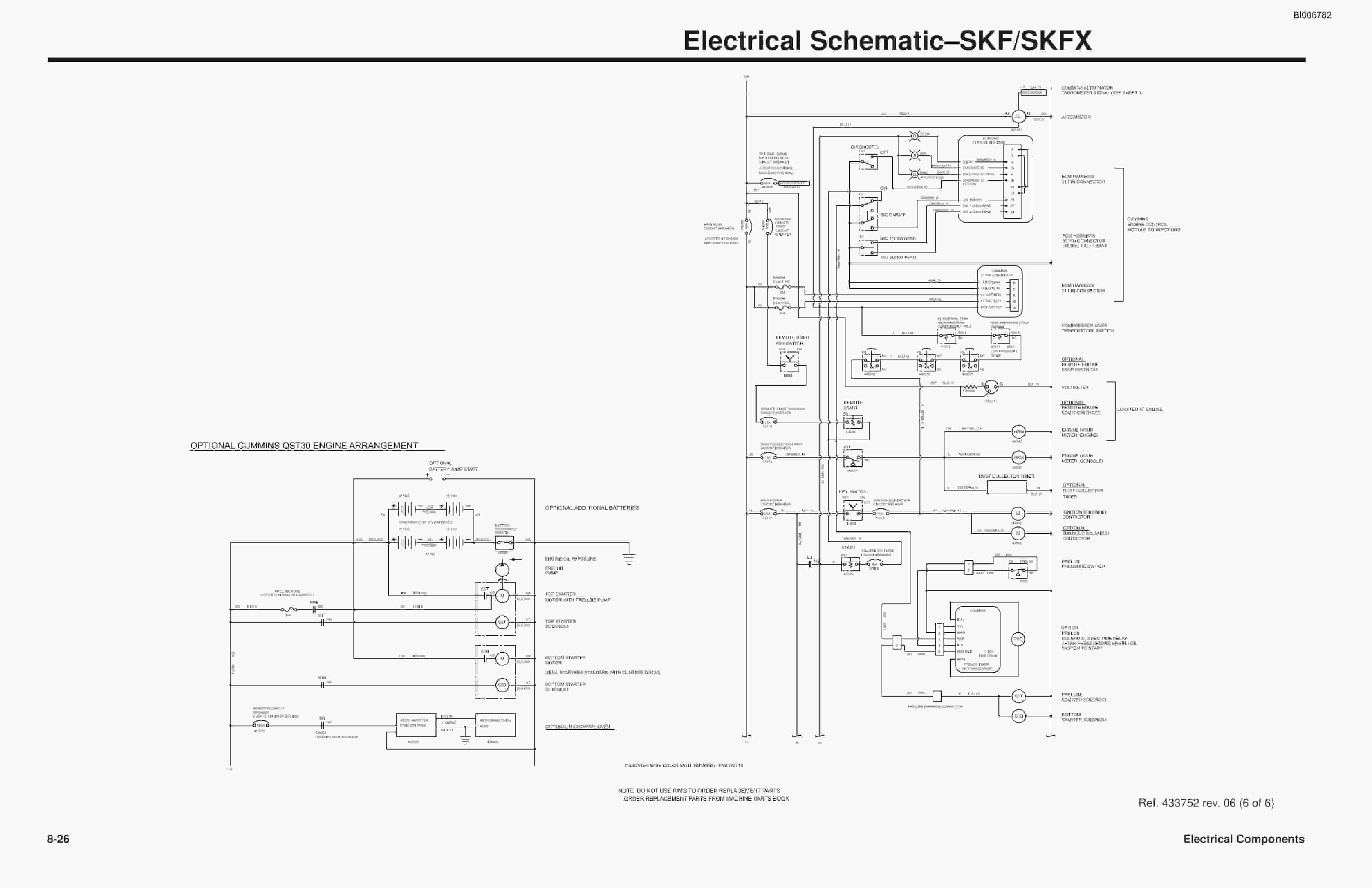
- 15.18. Electrical SchematicSKF/SKFX
- 15.19. Electrical SchematicSKF (Cat)
- 15.20. AC/Heater/Pressurizer Circuit
- 15.21. Remote Tram Installation
- 16. Section 9 – Lubrication and Preventative Maintenance
- 16.1. Service PointsMainframe
- 16.1.1. Auto Lube System
- 16.1.2. Manual Lube System
- 16.2. Service Points – General
- 16.3. LubricationGeneral
- 16.4. Lubrication and Maintenance Chart
- 16.5. Lubricant Specifications
- 16.5.1. Hydraulic System
- 16.5.2. Compressor
- 16.5.3. Final Drive Oil
- 16.5.4. Lubricating Grease
- 16.5.5. Gear Lubricant
- 16.5.6. Engine Oil (Caterpillar)
- 16.5.7. Engine Oil (Cummins)
- 16.6. Extreme Weather Lubricants
- 16.7. Preventative Maintenance
- 16.7.1. Mast Trunnion Bolt Torque
- 16.7.2. Charge and Loop Filters
- 16.7.3. Hydraulic System
- 16.7.4. Compressor Lubrication
- 16.7.5. Cat Pump Oil
- 16.7.6. Water Pump (Cat Pump)
- 16.7.7. Cooling SystemCummins
- 16.7.8. Cooling SystemCaterpillar
- 16.7.9. Air Cleaners
- 16.7.10. Mast Pivot Shaft Inspection and Repair
- 16.7.11. Weld Inspection
- 16.7.12. Bolted Joint Maintenance
- 16.7.13. SAE Recommended Torque Values
- 16.7.14. Critical Fastener ID Inspection Schedule
- 16.7.15. Electrical System
- 16.7.16. Extended Machine Shutdown
- 16.7.17. Scheduled Oil Sampling Analysis
- 16.8. Drill Stem Thread Lubricator
- 16.9. Metric Conversions
- 16.10. Torque Values for Split Flange Connections
- 16.11. Torque Values for Hydraulic Tubes Fittings
- 16.12. Maintenance Record
- 17. Section 10 – Optional Equipment
- 17.1. Auto Lube System
- 17.1.1. Lube Pump Air Motor
- 17.1.2. Auto Lube Injectors
- 17.1.3. Filter/Regulator/Lubricator
- 17.1.3.1. Filter Maintenance and Repair
- 17.1.3.2. Regulator Maintenance and Repair
- 17.1.3.3. Lubricator Maintenance and Repair
- 17.1.4. Lube Controller Manual
- 17.2. Drill Stem Thread Lubricator
- 17.2.1. Filter Assembly
- 17.2.2. Air Pressure Regulator
- 17.2.3. Lubricator Assembly
- 17.2.4. Way Air Valve
- 17.2.5. Grease Pump
- 17.3. Drilling Efficiency Indicator
Related products
-
Caterpillar 4G63, 4G64 Gasoline Engine Service Manual 99729-84120
$50.00 Add to cart -
Caterpillar 1204E Diesel Engine Operation and Maintenance Manual Service Manual 99799-64105
$50.00 Add to cart -
Caterpillar 1204F Diesel Engine Specifications Service Manual 99799-67101
$50.00 Add to cart -
Caterpillar 1204F Diesel Engine Service Manual SCEEA-AT15F-200
$50.00 Add to cart -
Caterpillar 2P3000 to 2PD7000, GP15NM-35NM Chassis and Mast Service Manual 99719-8M110
$50.00 Add to cart


