

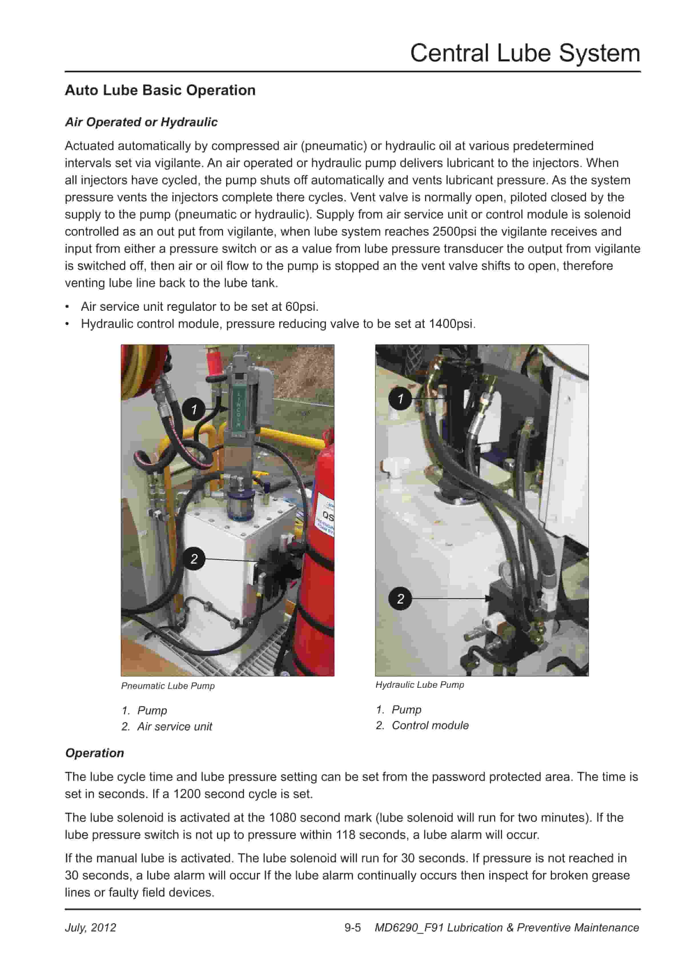
Caterpillar MD6290 Rotary Blasthole Drill Service Manual 91-A13-037
$30.00
- Type Of Manual: Service Manual
- Manual ID: 91-A13-037
- Number of Pages: 640
- Size: 147.1MB
- Format: PDF
Product details
-
Model List:
- MD6290 Rotary Blasthole Drill
- 1. MD6290 F91 Service Manual
- 1.1. Parts Ordering and Product Support
- 2. Section 1 Safety
- 2.1. Contents
- 3. Section 2 Operators Cab / Controls
- 3.1. Contents
- 3.2. Graphic Symbol Legend
- 3.3. Warning Decals
- 3.4. Operator Control and Instrument Panels
- 3.5. System Pressure Gauge Panel
- 3.6. Switch Panel
- 3.7. Switches / Diagnostic / Control Panel Circuit
- 3.8. Machine Stability
- 3.9. General Maintenance Checks While Tramming
- 3.10. New Machine Procedure
- 3.11. Roller Locations
- 3.12. Temperature and Condition Record Chart for Walking
- 3.13. Propelling the Machine
- 3.14. Stability Limits
- 3.15. SKSS Transient Stability Limits
- 3.16. Cab Heater
- 3.17. Air Conditioner
- 3.18. Section 1.0 Technical Data and Control Settings
- 3.19. Section 2.0 Installation and Commissioning
- 3.20. Section 3.0 Routine Maintenance Procedures
- 3.21. Section 4.0 Fault Diagnosis
- 3.22. Section 5.0 Reference Drawings
- 4. Section 3 Main Frame Crawlers
- 4.1. Contents
- 4.2. Main Frame Repair – General
- 4.3. Weld Inspection Schedule
- 4.4. Levelling Jacks
- 4.5. Levelling Jack Cylinders
- 4.6. Limit Switch
- 4.7. Levelling Jacks
- 4.8. Mast Elevating Cylinders
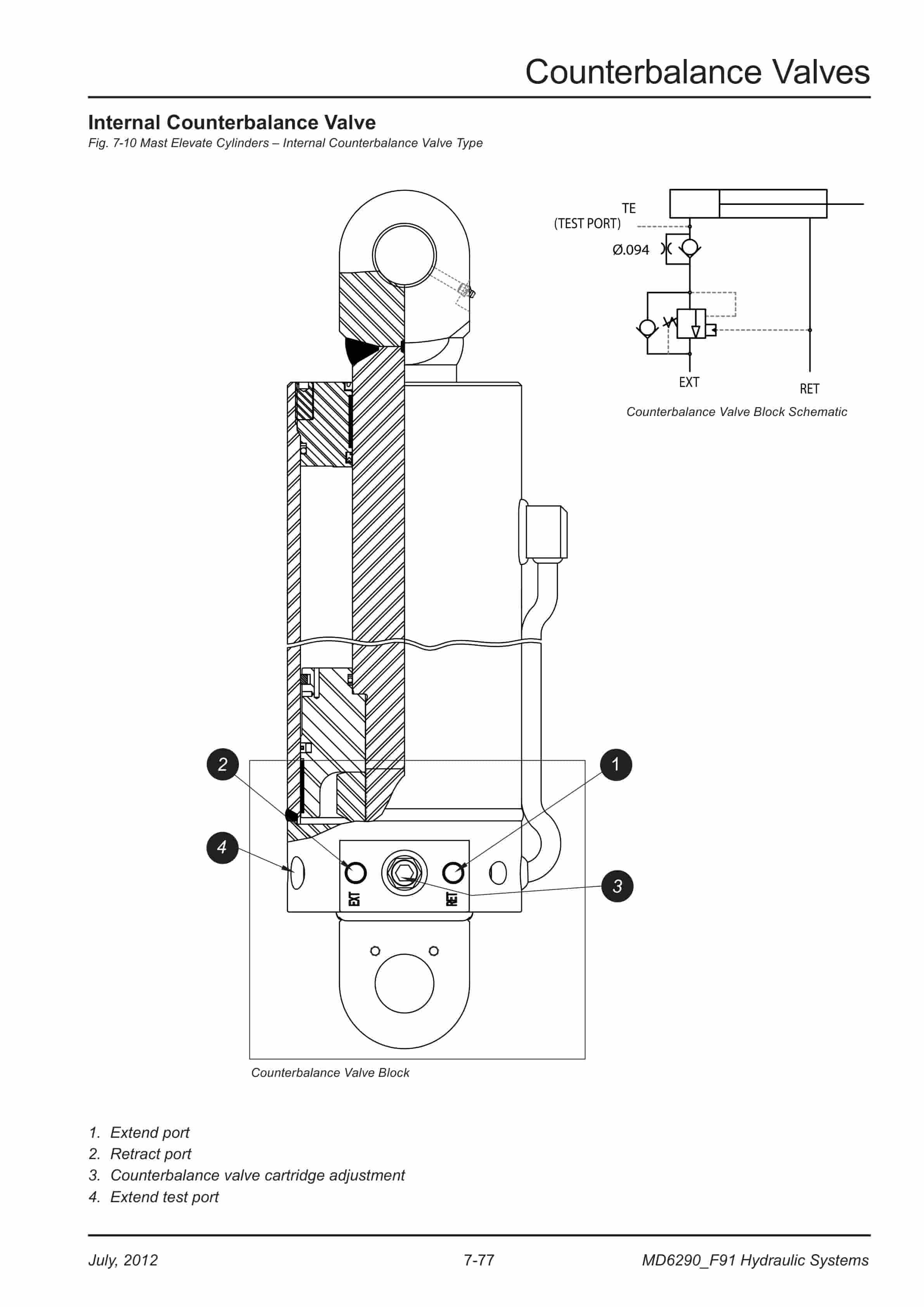
- 4.9. Internal Counterbalance Valve
- 4.10. Fuelling Valves
- 4.11. Crawler Assembly
- 4.12. Crawler Component Repair
- 4.13. Tramming
- 4.14. General Maintenance Checks While Tramming
- 4.15. New Machine Procedure
- 4.16. Roller Locations
- 4.17. Temperature and Condition Record Chart for Walking
- 4.18. Metric Bolt Torque
- 4.19. Track Maintenance
- 4.20. Track Tension
- 4.21. Track Tension Adjustment
- 4.22. Track Tension Unit
- 4.23. Track and Support Rollers
- 4.24. Support Roller Unit
- 4.25. Support Rollers
- 4.26. Track Chain
- 4.27. Track Shoes Installation
- 4.28. Track Shoe Bolt Torque (Direct Torque Method)
- 4.29. Track Shoe Bolt Torque (Torque Turn Method)
- 4.30. Track Chain and Shoe Installation
- 4.31. Final Drive Unit
- 4.32. Removal from Track Frame
- 4.33. Installation into Track Frame
- 4.34. Final Drive Maintenance
- 4.35. Final Drive Oil
- 4.36. Final Drive Assembly
- 4.37. Parking Brake Description
- 4.38. General Recommendations for Disassembly and Assembly Operations
- 4.39. General Description
- 4.40. Towing Procedure Gear Drive Disconnect
- 4.41. Final Drive Disconnect and Parking Brake
- 4.42. Parking Brake
- 4.43. Sealing Compounds and Adhesives
- 4.44. Service Schedule
- 4.45. Filling and Checks
- 4.46. Lubrication / Greasing Grades and Application Range
- 4.47. Tightening Torques
- 4.48. Special Tools
- 4.49. Troubleshooting
- 4.50. Idler Unit
- 4.51. Track and Sprocket Inspection
- 4.52. Sprocket Wear Patterns
- 4.53. Auxiliary Crane
- 4.54. Checking Bolted Connections
- 4.55. Rear Deck Crane Palfinger PC1500 Service information
- 4.56. Maintenance Chart
- 4.57. Lubrication
- 4.58. Hydraulic Fluids
- 4.59. Removal From Service and Disposal
- 4.60. Repairing Paint Damage
- 4.61. Cleaning Agents and Equipment
- 4.62. Oil Change / Oil Maintenance
- 5. Section 4 Engine / Drive Train / Compressor
- 5.1. Contents
- 5.2. Power Group Locator
- 5.3. Test Point Locator
- 5.4. Test Point Locator
- 5.5. Oil Reserve Systems
- 5.6. Adjustment of Running Oil Level
- 5.7. LED Monitor Readings
- 5.8. Oil Reserve System
- 5.9. Oil Pressure Switch
- 5.10. Wiring Diagram Oil Reserve Basic Circuit
- 5.11. Maintenance
- 5.12. Troubleshooting
- 5.13. Engine Fuel System QSK19 Tier II
- 5.14. Fuel Plumbing
- 5.15. Filtration Hardware Mounting
- 5.16. Installation and Operation Recommendations
- 5.17. Installation Requirements
- 5.18. Fuel Filter (Stage 1)
- 5.19. Fuel Filter (Stage 2)
- 5.20. Engine and Compressor Air Cleaners
- 5.21. Engine and Compressor Air Cleaner Service
- 5.22. Flexible Drive Coupling
- 5.23. Pump Drive
- 5.24. Pump Drive Gearbox Repair
- 5.25. Pump Drive Gearbox
- 5.26. Hydraulic Pumps
- 5.27. Hydraulic Pumps Removal and Replacement
- 5.28. Compressor Installation
- 5.29. Compressor Installation
- 5.30. Compressor Drive Coupling
- 5.31. Compressor Alignment
- 5.32. Mounting Instructions for Arcusaflex Flywheel Couplings
- 5.33. Tightening Torques for Arcusaflex Flywheel Couplings
- 5.34. Taper-Loc Bushing Installation Model AC-T5.SN. F2. V1. 3535
- 5.35. Compressor Shaft Seal
- 5.36. Low Pressure Compressor
- 5.37. Compressor Inlet Valve Control System
- 5.38. Inlet Valve
- 5.39. Compressor Regulation
- 5.40. Relieving Regulators
- 5.41. Reducing Regulators
- 5.42. System Blowdown Valve
- 5.43. Running Blowdown Valve
- 5.44. Compressor Air and Oil Circuits 1700cfm 100psi
- 5.45. Spiral valve
- 5.46. Compressor Air Circuit Legend
- 5.47. Compressor Air Circuit Parts List
- 5.48. Compressor Control Set-up Vented Poppet Inlet Shutdown
- 5.49. Compressor Control Set-up Vented Poppet Inlet Initial Start-up Below 50psi
- 5.50. Compressor Control Set-up Vented Poppet Inlet Initial Start-up Above 50psi
- 5.51. Compressor Control Set-up Vented Poppet Inlet Run Unloaded
- 5.52. Compressor Control Set-up Vented Poppet Inlet Drilling
- 5.53. Compressor Control Set-up Vented Poppet Inlet Shutting Down
- 5.54. Operation
- 5.55. Compressor Maintenance
- 5.56. Discharge Check Valve
- 5.57. Compressor Receiver Tank Assembly
- 5.58. Separator Elements
- 5.59. Scavenge Line
- 5.60. Compressor Discharge Temperature Gauge, Switch and Sender
- 5.61. Minimum Pressure / Check Valve Maintenance
- 5.62. Minimum Pressure Valve
- 5.63. Thermal Bypass Valve
- 5.64. Thermal Bypass Valve Maintenance
- 5.65. Troubleshooting
- 5.66. Oil stop valve
- 5.67. Changing Filter Elements
- 5.68. Compressor Fluid Filter
- 5.69. Coolers
- 5.70. Fan Speed
- 5.71. Compressor Oil Cooler
- 5.72. Engine Cooler / Radiator
- 5.73. Aluminium Tube Air to Oil Cooler
- 5.74. Removal and Replacement
- 5.75. Internal Cleaning
- 5.76. Radiator Cooler
- 5.77. Cleaning
- 5.78. Tube Removal
- 5.79. Lubricating Seals and Tube Ends
- 5.80. Seal Installation
- 5.81. Tube Installation
- 6. Section 5 Dust Control System
- 6.1. Contents
- 6.2. Dust Control System
- 6.3. Water Injection
- 6.4. Water Tanks
- 6.5. Water Injection Relief Valve
- 6.6. Water Injection Pump
- 6.7. Water Injection Control
- 6.8. Water Injection
- 6.9. Water Pump
- 6.10. Servicing the Plunger Packings
- 6.11. Servicing Instructions
- 6.12. Torque Requirements
- 6.13. Pump Specifications
- 6.14. Reassembling Valve Parts
- 6.15. Servicing the Pump Valves
- 6.16. Reassembling Plunger Packings
- 6.17. Servicing the Crossheads
- 6.18. Servicing the Crankshaft
- 6.19. Replacing Piston Cup Seals
- 6.20. Replacing Suction and Discharge Valves
- 6.21. Replacing Power End Bearings
- 6.22. Fastener Torque Requirements
- 6.23. Servicing the Wrist Pin Bearings
- 6.24. Level and Flow Transducer
- 6.25. Water Pump Drive Coupling
- 6.26. Water Pump Motor Repair
- 6.27. Recommended Lubricants
- 7. Section 6 Mast / Rotary Drive / Pipe Rack
- 7.1. Contents
- 7.2. Mast Weldment
- 7.3. Weld Inspection Schedule
- 7.4. Mast Assembly and Installation
- 7.5. Mast Pivot Caps
- 7.6. Angle Drilling
- 7.7. Mast Elevate Cylinders
- 7.8. Mast / Drill Without Mast
- 7.9. Raising the Mast
- 7.10. Mast Assembly
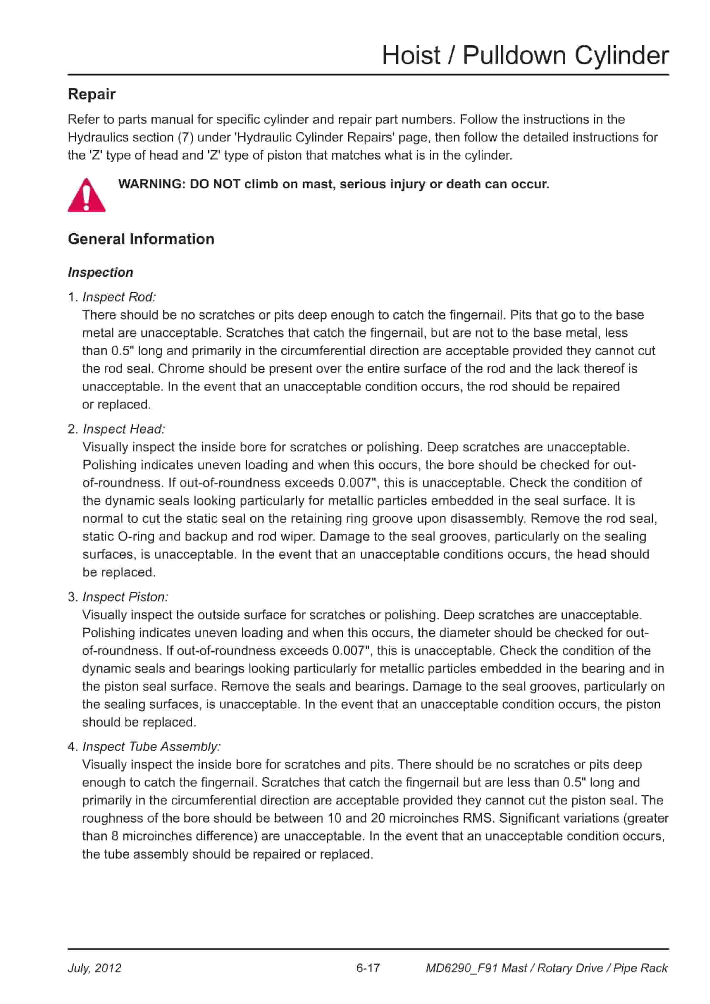
- 7.11. Hoist / Pulldown Cylinder
- 7.12. Feed Cylinder System
- 7.13. Removal
- 7.14. Installation
- 7.15. General Information
- 7.16. Hoist / Pulldown Cable
- 7.17. Hoist / Pulldown Cable Replacement
- 7.18. Wire Rope
- 7.19. Rotary Drive
- 7.20. Rotary Drive Assembly
- 7.21. Rotary Drive Installation
- 7.22. Rotary Drive Removal from Mast
- 7.23. Single Motor Rotary Drive Gearbox
- 7.24. Manufacturers Recommendations Blast Hole Drilling Consumables
- 7.25. Air Swivel (Single Seal Style)
- 7.26. Rotary Drive Motor Repair
- 7.27. Torque Limit Table Grade 8 UNC
- 7.28. Torque Limit Table Grade 8 UNF
- 7.29. Rotary Drive Motor
- 7.30. Deck Wrench
- 7.31. O Wrench
- 7.32. Tong Dies
- 7.33. Pipe Positioner
- 7.34. Carousel Pipe Rack
- 7.35. Pipe Rack Bearings Replace
- 7.36. Carousel Top Tube Bearing Replace
- 7.37. Carousel Lower Bearing Replace
- 7.38. Upper Pivot Support Bearing
- 7.39. Carousel Pivot Support Upper Bearing Replace
- 7.40. Pivot Support Pipe Lower Bushing
- 7.41. Carousel Pivot Support Lower Bearing Replace
- 7.42. Carousel Rotate Motor
- 7.43. Mid Point Carousel Pivot Support
- 7.44. Top Sub Saver (Optional)
- 8. Section 7 Hydraulic Systems
- 8.1. Contents
- 8.2. Hydraulic Symbols
- 8.3. Pressure Setting Sequence
- 8.4. Main Hydraulic Pumps
- 8.5. Hydraulic Tank
- 8.6. Hydraulic System
- 8.7. Main Return and Case Drain Filter
- 8.8. Changing Filter Elements
- 8.9. Routine Maintenance
- 8.10. Loop Filters
- 8.11. Loop Filter cross section
- 8.12. Filter Assembly Loop
- 8.13. Changing Filter Elements
- 8.14. Charge Circuit
- 8.15. Charge Circuit
- 8.16. Changing Filter Elements
- 8.17. Set Charge Pressure 350psi (24bar)
- 8.18. Charge Pressure
- 8.19. Charge Pumps
- 8.20. Main Pumps Circuit
- 8.21. Right Track / Left Track / Rotation Pumps
- 8.22. Dimensions
- 8.23. Operational Parameters
- 8.24. Controls
- 8.25. EP (24V DC) Control
- 8.26. Main Pumps
- 8.27. Hydraulic Piston Pumps Removal and Replacement
- 8.28. Main Pump Adjustments
- 8.29. Technical Data
- 8.30. Setting Linde HPV-02 Main pumps Neutral Setting
- 8.31. Setting Linde HPV-02 Main pumps Pressure Settings
- 8.32. Setting Linde HPV-02 Main pumps Pre-setup Checks
- 8.33. Main Pumps Linde HPV-02
- 8.34. Setting Procedure
- 8.35. Diverter Valve
- 8.36. Rotation Circuit
- 8.37. Rotation Circuit
- 8.38. Tram Circuit
- 8.39. Brake Test Procedure
- 8.40. Rotary Drive Gearbox Motor
- 8.41. Rotation Motor
- 8.42. Pilot Control Manifold
- 8.43. Pilot Control Manifold Assembly
- 8.44. Control Valve Assembly
- 8.45. Electro Proportional Valves
- 8.46. Auto Pulldown Card
- 8.47. Proportional Valve set-up
- 8.48. Torque Control
- 8.49. Proportional Pulldown
- 8.50. OEM Controllers / EP Levers
- 8.51. Auxiliary Pump Circuit
- 8.52. Linde HPR-02 Self-Regulating Pump
- 8.53. Feed and Auxiliary Functions Pump
- 8.54. Linde HPR-02 Self-Regulating Pump
- 8.55. Hydraulic Piston Pumps Removal and Replacement
- 8.56. Auxiliary Circuit
- 8.57. Auxiliary Valves
- 8.58. Jack Control and Mast Elevating Circuit
- 8.59. Jack Control and Mast Elevating Control Valve
- 8.60. Jack Control and Mast Elevating Circuit
- 8.61. Counterbalance Valves
- 8.62. Internal Counterbalance Valve
- 8.63. Levelling Jack Cylinders
- 8.64. Mast Elevating Cylinders
- 8.65. Hydraulic Operated Breakout Wrench
- 8.66. o Float Valve
- 8.67. Setting of H.O.B.O Sequence Valves
- 8.68. Hydraulic Feed Circuit
- 8.69. Hoist and Pulldown Control
- 8.70. Feed Valve Assembly
- 8.71. Control Valve Assembly
- 8.72. Cooler Fan Circuit
- 8.73. Hydraulic cooler Thermal valve
- 8.74. Basic Cooler Fan Circuit
- 8.75. Cooler Fan Motor
- 8.76. Hydraulic Motor
- 8.77. Water Pump Motor
- 8.78. Shaft Seal Repair
- 8.79. Hydraulic Cylinder Repair
- 8.80. General Information
- 8.81. Z Head (Two Piece)
- 8.82. Z Piston
- 8.83. Z Piston (Threaded)
- 8.84. H and K Piston
- 8.85. M Piston
- 8.86. N Piston
- 8.87. Hydraulic Systems
- 9. Section 8 Electrical Components
- 9.1. Contents
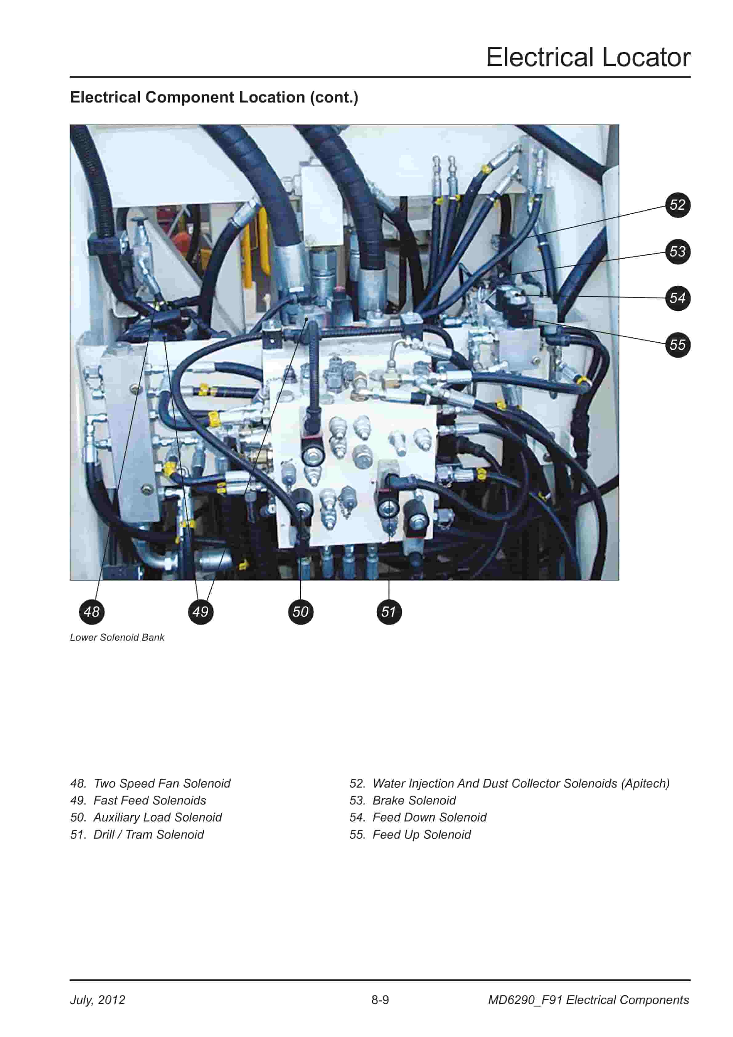
- 9.2. Electrical Locator
- 9.3. Jump Starting
- 9.4. Batteries
- 9.5. Welding Precautions
- 9.6. Electrical Components
- 9.7. EP Levers
- 9.8. Joystick Adjustments
- 9.9. Vigilante Guide
- 10. Section 9 Lubrication
- 10.1. Contents
- 10.2. Central Lube System
- 10.3. Air Service Units
- 10.4. Air Line Oiler
- 10.5. Soft Start Dump Valve
- 10.6. Air Service Unit
- 10.7. Pipe Thread Lubricator
- 10.8. Filter Locator
- 10.9. Lubrication Preventive Maintenance
- 10.10. Weld Inspection Schedule
- 10.11. Critical Fasteners
- 10.12. Critical Fastener ID and Inspection Schedule
- 10.13. Externally Threaded SAE ASTM Fasteners
- 10.14. Torque Values
- 10.15. Track and Sprocket Inspection
- 10.16. Sprocket Wear Patterns
- 10.17. Lubrication Recommendations
- 10.18. Lubrication Maintenance Chart – 250hr
- 10.19. Lubrication Maintenance Chart – 500hr
- 10.20. Lubrication Maintenance Chart – 1000hr
- 10.21. Lubrication Maintenance Chart – 2000hr
- 10.22. Lubricant Specifications
- 10.23. Compressor Lubricant Specifications
- 10.24. Compressor Lubrication
- 10.25. Scheduled Oil Sampling Analysis
- 10.26. Gear Lubricant
- 10.27. Lubricating Grease
- 10.28. Torque Values for Split Flange Connections
- 10.29. Procedure No. 1-87 Revision A
Related products
-
Caterpillar 1204E Diesel Engine Specifications Service Manual 99799-64101
$50.00 Add to cart -
Caterpillar 4G63, 4G64, 6G72 Liquefied Petroleum Gas Supplement Service Manual 99729-85100
$50.00 Add to cart -
Caterpillar 2EC15-30 Chassis and Mast Service Manual 99759-80100
$50.00 Add to cart -
Caterpillar 1204F Diesel Engine Specifications Service Manual 99799-67101
$50.00 Add to cart -
Caterpillar 1.4 Liter (4G33) to 3.0 Liter (6G72) LP Gas Supplement Service Manual SENB8531
$50.00 Add to cart


%20to%203.0%20Liter%20(6G72)%20LP%20Gas%20Supplement%20Service%20Manual%20SENB8531&url=https://ownersmanualpdf.net/docs/caterpillar-1-4-liter-4g33-to-3-0-liter-6g72-lp-gas-supplement-service-manual-senb8531/&media=https://ownersmanualpdf.net/wp-content/uploads/2025/10/caterpillar-14-liter-4g33-to-30-liter-6g72-lp-gas-supplement-service-manual-senb8531-1.jpg)