

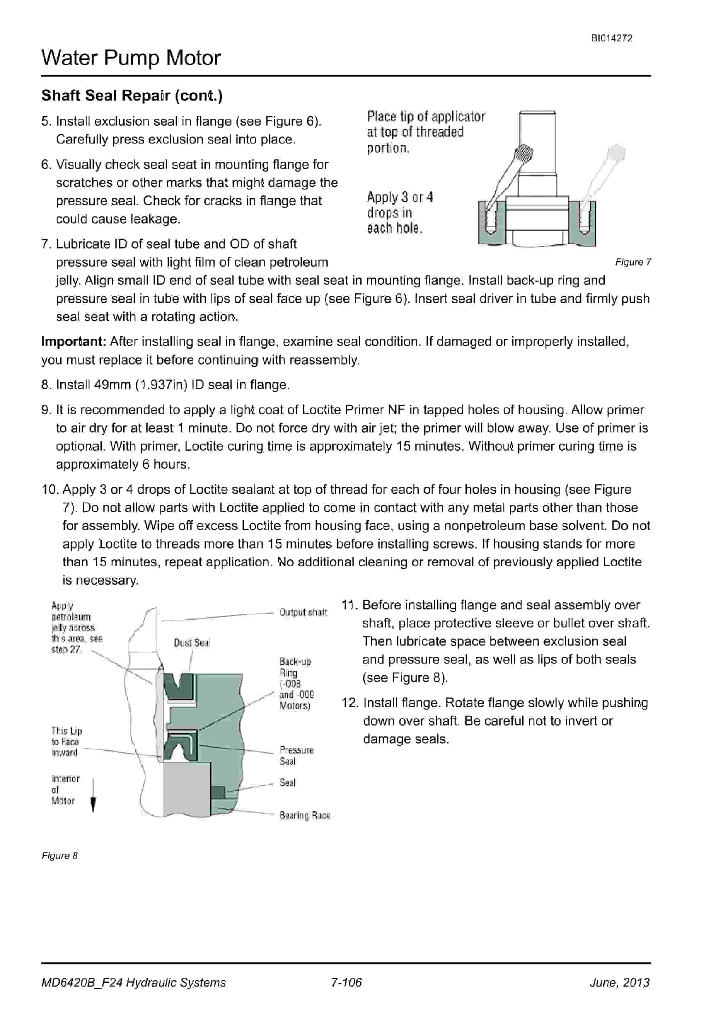
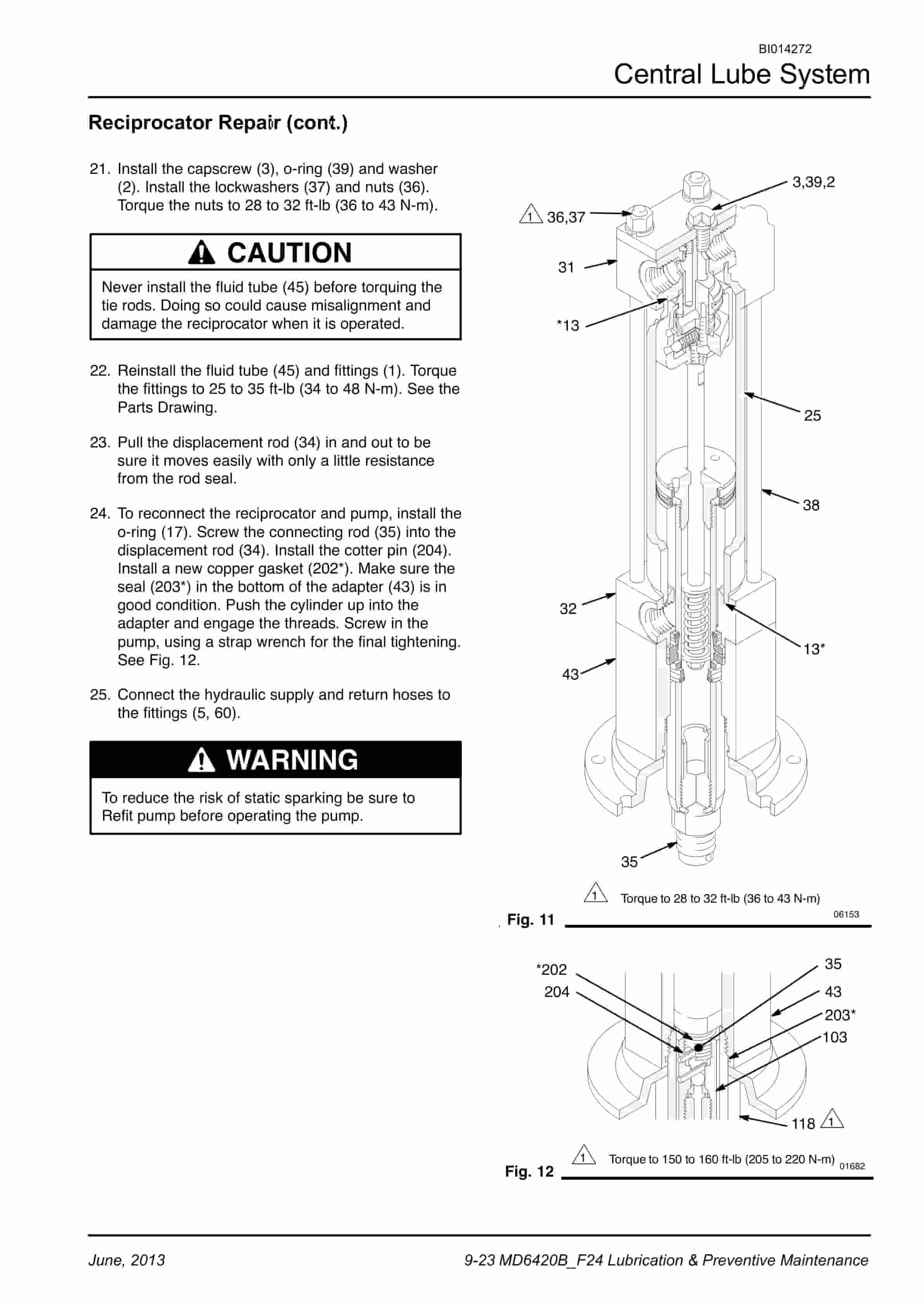

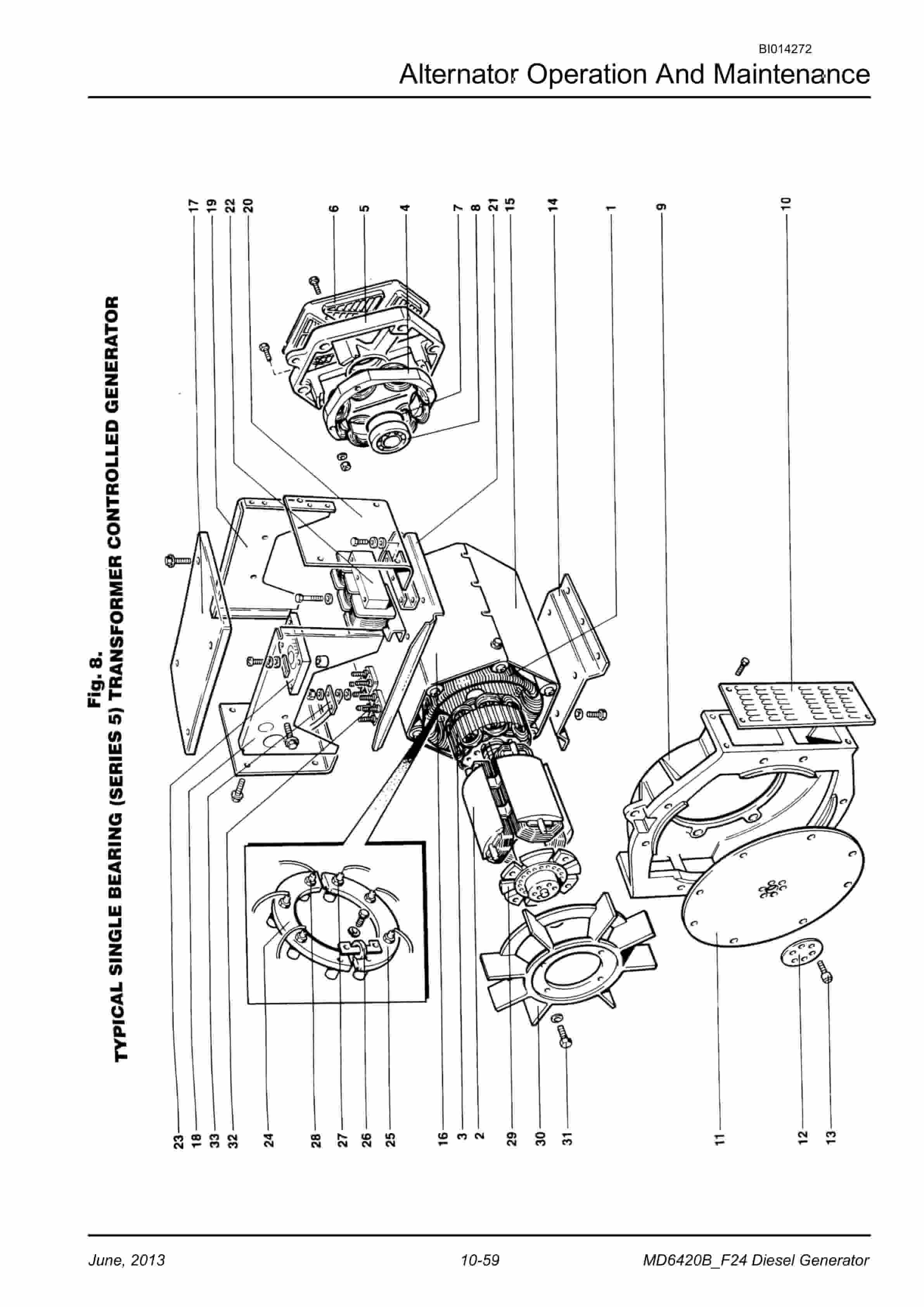
Caterpillar MD6420B Rotary Blasthole Drill Service Manual BI014272
$30.00
- Type Of Manual: Service Manual
- Manual ID: BI014272
- Number of Pages: 1068
- Size: 209.0MB
- Format: PDF
Product details
-
Model List:
- MD6420B Rotary Blasthole Drill
- 1. CAT MD6420B F24 REV.01 SERVICE MANUAL
- 1.1. Safety Information
- 1.2. Contents
- 1.3. General Locator
- 1.3.1. General Locator
- 2. CAT MD6420B F24 REV.01 SECTION ONE
- 2.1. Section 1 Contents
- 2.1.1. Overview of Potential Hazards
- 2.1.2. Personal Protective Equipment
- 2.1.3. Electrical Contact
- 2.1.4. Overhead and Buried Utilities
- 2.1.5. Clearances from Overhead High Voltage Lines
- 2.1.6. Contact with Electric Wires
- 2.1.7. Contaminated Air
- 2.1.8. Moving and Rotating Parts
- 2.1.9. High Pressure Air or Fluid
- 2.1.10. Before Operation
- 2.1.11. During Operation
- 2.1.12. Maintenance
- 2.1.13. Equipment Transfer
- 2.1.14. Safety Locator
- 3. CAT MD6420B F24 REV.01 SECTION TWO
- 3.1. Section 2 Contents
- 3.2. Graphic Symbol Legend
- 3.3. Warning Decals
- 3.4. Operating System Help Table Icons
- 3.4.1. Instrument Panel
- 3.4.2. Control Junction Box
- 3.4.3. Control Selection SW
- 3.4.4. Local – Control Panel
- 3.4.5. Pedestal Control Optional
- 3.4.6. Guide To Tablet PC
- 3.4.7. Local Remote
- 3.4.8. Using Local Remote
- 3.4.9. Login Screen
- 3.4.10. Dashboard
- 3.4.11. Login Screen
- 3.4.12. Local Remote – Main Page
- 3.4.13. Remote Mode Selection And Indication
- 3.4.14. RC Mode Selection
- 3.4.15. Auxiliary
- 3.4.16. Natural
- 3.4.17. Remote Control Screens
- 3.4.18. Remote Mode Selection And Indication
- 3.4.19. Drill Control Page Drill Mode
- 3.4.20. Digital Or Bang Bang Functions
- 3.4.21. Proportional Functions
- 3.4.22. Auxiliary Control Page Drill Mode
- 3.4.23. ABC or Auto Bit Changer
- 3.4.24. Level Control Page Tram Mode
- 3.4.25. Shutting Down And Isolation
- 3.4.26. Face Plate Features
- 3.4.27. Navigation And Keypad Functions
- 3.4.28. Basic Navigation
- 3.4.29. Operation
- 3.4.30. PowerView Menus (First Time Start Up)
- 3.4.31. Setting Up The Display
- 3.4.32. Up Display
- 3.4.33. Up Display Settings
- 3.4.34. Up Display
- 3.4.35. Main Menu Options
- 3.4.36. Selecting A Language
- 3.4.37. Stored Fault Codes
- 3.4.38. Engine Configuration Data
- 3.4.39. Service Reminders
- 3.4.40. Select Units
- 3.4.41. Backlight Adjustment
- 3.4.42. Contrast Adjustment
- 3.4.43. Utilities Menu
- 3.4.44. Gage Data
- 3.4.45. Remove All Gages
- 3.4.46. Software Version
- 3.4.47. Modbus Setup
- 3.4.48. Fault Conversion
- 3.4.49. Analog Input
- 3.4.50. OEM Menu
- 3.4.51. MODBUS Setup
- 3.4.52. CANBUS Data Rate
- 3.4.53. Select Engine ECU
- 3.5. Advanced Drill Automation System (ADAS)
- 3.5.1. Drill Monitor
- 3.5.2. Operation Controls
- 3.5.3. Function And Number Keys
- 3.5.4. LED states / Operating States
- 3.5.5. Touch Screen Operation And Care
- 3.5.6. Touch Screen Operation
- 3.5.7. Cleaning The Housing
- 3.5.8. Cleaning The Touch Screen
- 3.5.9. Login Screen
- 3.5.10. Dashboard
- 3.5.11. Login Screen
- 3.5.12. Login Screen Updates
- 3.5.13. Bit Settings
- 3.5.14. Hour Meters
- 3.5.15. Time Management
- 3.5.16. Drill Screen
- 3.5.17. Drill Screen Updates
- 3.5.18. Pull Down Gauge Operation
- 3.5.19. Depth System
- 3.5.20. Drill Status And Override Updates
- 3.5.21. Drill Status And Override
- 3.6. Machine Stability
- 3.6.1. Tramming Procedure
- 3.6.2. Requirements For Propelling The Machine
- 3.6.3. Track Adjustments
- 3.6.4. New Machine Procedure
- 3.6.5. General Maintenance Checks While Tramming
- 3.6.6. Roller Locations
- 3.6.7. Temperature And Condition Record Chart For Walking
- 3.6.8. Propelling The Machine
- 3.6.9. Propelling Through Turns
- 3.6.10. Propelling Up, Down And Across Grades
- 3.6.11. Stability Limits
- 3.6.12. md6420b – 16 Transient Stability Limits
- 4. CAT MD6420B F24 REV.01 SECTION THREE
- 4.1. Section 3 Contents
- 4.2. Main Frame Repair – General
- 4.2.1. Main Frame Repair
- 4.3. Weld Inspection Schedule
- 4.3.1. Main Frame
- 4.4. Levelling Jacks
- 4.4.1. Levelling Jack Cylinder
- 4.4.2. Limit Switch
- 4.4.3. Removal
- 4.5. Jack Cylinder Removal / Replacement
- 4.5.1. Lubricating Jack Casings
- 4.5.2. Replace Jack Cylinder
- 4.6. Mast Elevating Cylinders
- 4.7. Mast Raise Cylinders
- 4.7.1. Mast Raise Cylinder Removal
- 4.7.2. Mast Raise Cylinder Installation
- 4.8. Mast Elevating Cylinders
- 4.8.1. Internal Counterbalance Valve
- 4.9. Fuelling Valves
- 4.9.1. Fuelling Valves
- 4.9.2. Non-pressurised Fuelling System Operation
- 4.9.3. Fuelling Valves
- 4.9.4. Conventional Systems
- 4.10. Fuelling Valves
- 4.10.1. Parts List
- 4.10.2. Crawler Assembly
- 4.10.3. Parts List
- 4.10.4. Crawler Component Repair
- 4.11. Tramming
- 4.11.1. Maintenance Checks For Tramming For Caterpillar Drills
- 4.11.2. Requirements For Propelling The Machine
- 4.11.3. Track Adjustments
- 4.11.4. New Machine Procedure
- 4.11.5. General Maintenance Checks While Tramming
- 4.11.6. Roller Locations
- 4.11.7. Temperature And Condition Record Chart For Walking
- 4.12. Metric Bolt Torque Specifications
- 4.12.1. Metric Bolt Torque Specifications
- 4.13. Track Tension Adjustment
- 4.13.1. Before Operating The Machine
- 4.13.2. General Maintenance
- 4.13.3. Track Assembly
- 4.13.4. Idler Unit Description
- 4.13.5. Hydraulic Tensioner
- 4.13.6. Proper Track Tension
- 4.13.7. Nitrogen Tensioner
- 4.14. Track Chain
- 4.14.1. Track Chain
- 4.14.2. Track Link Position
- 4.14.3. Track Shoe Mounting To Track Chain
- 4.15. Track Shoes Installation
- 4.15.1. Bolt Torque KN111
- 4.16. Track Shoe Bolt Torque (Direct Torque Method)
- 4.17. Track Chain and Shoe Installation
- 4.17.1. Track Chain With Shoes
- 4.18. Final Drive Unit
- 4.18.1. General Description
- 4.18.2. Removal From Track Frame
- 4.18.3. Installation Into Track Frame
- 4.18.4. Final Drive Maintenance
- 4.18.5. Final Drive Oil
- 4.18.6. F130 Final Drive Assembly
- 4.18.7. Parts List
- 4.18.8. F130 Final Drive
- 4.18.9. Service Information
- 4.18.10. Tightening Torques
- 4.18.11. Planetary Gears F130/206-A
- 4.18.12. Disassembly
- 4.18.13. Troubleshooting
- 4.18.14. Idler Unit Assembly
- 4.18.15. Idler Unit Removal
- 4.18.16. Track Roller Assembly
- 4.18.17. General Description
- 4.18.18. Track Roller Removal And Disassembly
- 4.18.19. Support Roller Removal And Disassembly
- 4.18.20. Track And Support Roller Assembly
- 4.18.21. Track and Support Roller Test And Install
- 4.18.22. Track Inspection and Wear Limit Guide
- 4.18.23. B8 Track Inspection And Wear Limit Guide Caterpillar Series Drills
- 4.18.24. Sprocket Wear Patterns
- 4.18.25. Wear on Forward Drive Side
- 4.18.26. Causes
- 4.18.27. Effects
- 4.18.28. Remedies
- 4.18.29. Wear on Reverse Drive Side
- 4.18.30. Causes
- 4.18.31. Effects
- 4.18.32. Remedies
- 4.18.33. Root Wear
- 4.18.34. Causes
- 4.18.35. Effects
- 4.18.36. Remedies
- 4.18.37. Wear of Tooth Tip
- 4.18.38. Causes
- 4.18.39. Effects
- 4.18.40. Remedies
- 4.18.41. Tooth Tip Broken Off
- 4.18.42. Causes
- 4.18.43. Effects
- 4.18.44. Remedies
- 4.18.45. Facial Wear
- 4.18.46. Causes
- 4.18.47. Effects
- 4.18.48. Remedies
- 4.19. Palfinger Crane
- 4.19.1. Radio Remote Control For PC Cranes
- 4.19.2. Rope winch for PC cranes
- 4.19.3. Control Valve And Housing
- 4.19.4. Rope Winch
- 4.19.5. Technical Data Sheet
- 4.19.6. Further Information
- 4.20. Auxiliary Crane
- 4.20.1. Hydraulic Crane Rear Deck Crane Palfinger PC1500
- 4.20.2. Rear Deck Crane Palfinger PC1500 Service information
- 4.20.3. Maintenance Chart
- 4.20.4. After the First 50 Hours
- 4.20.5. Lubrication
- 4.20.6. Lubricant To Be Used
- 4.20.7. Care Of Extendable Cylinder Piston Rods
- 4.20.8. Hydraulic Fluids
- 4.20.9. Hydraulic Fluids (cont.)
- 4.20.10. Note The Following Disadvantages
- 4.20.11. Oil Change / Oil Maintenance
- 4.20.12. Cleaning Agents and Equipment
- 4.20.13. Cleaning Agents
- 4.20.14. Repairing Paint Damage
- 4.20.15. Removal From Service And Disposal
- 5. CAT MD6420B F24 REV.01 SECTION FOUR
- 5.1. Section 4 Contents
- 5.2. Power Group Locator
- 5.3. Cummins Engine
- 5.3.1. Engine Fuel System
- 5.3.2. QST30 Electric Fuel Supply Flow Diagram
- 5.3.3. Construction
- 5.3.4. Electric Fuel Supply Pumps
- 5.3.5. Combo Fuel Filter Head And Pump Manifold
- 5.3.6. FS1006 Fuel Filter With Water Separator
- 5.3.7. Fuel Manifold With Integrated FSO Valve
- 5.3.8. Fuel Connections
- 5.3.9. Pre – Filters
- 5.3.10. Wiring With EFS Power Relay
- 5.3.11. Pressure And Temperature Sensors
- 5.3.12. Operation
- 5.3.13. QST30 Electric Fuel Supply System Flow Diagram
- 5.3.14. QST30 Electric Fuel Supply System Detail
- 5.3.15. Oil Reserve Systems
- 5.3.16. Operation
- 5.3.17. Engine Oil Reserve System (Basic Circuit)
- 5.3.18. LED Monitor Readings
- 5.3.19. Signals
- 5.3.20. Adjustment Of Running Oil Level
- 5.3.21. Wiring Diagram – Oil Reserve Basic Circuit
- 5.3.22. Oil Pressure Switch
- 5.3.23. Oil Reserve System
- 5.3.24. Troubleshooting
- 5.3.25. Maintenance
- 5.4. Engine and Compressor Air Cleaners
- 5.4.1. Engine And Compressor Air Cleaner Service
- 5.5. Flexible Drive Coupling
- 5.5.1. Flexible Drive Coupling Service
- 5.6. Pump Drive
- 5.6.1. Pump Identification
- 5.6.2. Pump Drive Assembly Removal And Replacement
- 5.6.3. Pump Drive Gearbox
- 5.6.4. Pump Drive Gearbox Repair
- 5.6.5. Input Shaft Assembly
- 5.7. Hydraulic Pumps
- 5.7.1. Hydraulic Pumps Removal And Replacement
- 5.8. Compressor Assembly
- 5.8.1. Drill Compressor Model 20/12 1475cfm 500psi
- 5.8.2. Compressor Drive Coupling
- 5.9. Compressor Installation
- 5.9.1. Compressor Drive Coupling Removal And Replacement
- 5.9.2. Compressor Unit Removal
- 5.10. Compressor Shaft Seal
- 5.10.1. Main Drive Shaft Seal Replacement
- 5.10.2. Inspection and Preparation For Seal Assembly
- 5.11. High Pressure Compressor
- 5.12. Compressor Oil Circuit
- 5.12.1. Compressor Oil Circuit – 1475cfm 500psi
- 5.13. Compressor Condensation Table
- 5.14. Compressor Air Circuit
- 5.14.1. Compressor Air Circuits 1475cfm 500psi
- 5.15. Compressor Functional Description
- 5.15.1. Compressor Air Circuit
- 5.15.2. Compressor Gauge
- 5.15.3. Compressor Control Valve
- 5.15.4. Compressor Run Valve
- 5.15.5. Compressor Run
- 5.15.6. Compressor Control Pressure Reducing Regulator
- 5.15.7. Compressor Air Circuit
- 5.16. Compressor Operation
- 5.16.1. Operation
- 5.16.2. Purpose Of Controls
- 5.17. Compressor Maintenance
- 5.17.1. General Maintenance
- 5.17.2. Interstage Tube
- 5.17.3. Flexible Pipe Coupling Maintenance
- 5.17.4. Discharge Check Valve
- 5.17.5. Separator / Receiver Tank
- 5.17.6. Scavenge Line
- 5.17.7. Compressor Discharge Temperature Switches, Senders And Gauges
- 5.17.8. Minimum Pressure / Check Valve
- 5.17.9. Minimum Pressure / Check Valve Maintenance
- 5.17.10. Thermal / Bypass Valve
- 5.17.11. Compressor Fluid Filter
- 5.17.12. Fluid Stop Valve
- 5.17.13. Inlet Valve
- 5.17.14. Reducing Regulator
- 5.17.15. System Blowdown Valve
- 5.17.16. Running Blowdown Valve
- 5.17.17. Running Blowdown Maintenance
- 5.17.18. Moisture Separator Maintenance
- 5.17.19. Auxiliary Regulator
- 5.17.20. Auxiliary Regulator Maintenance
- 5.17.21. Coolers Locator
- 5.17.22. Compressor Oil Cooler
- 5.18. Compressor / Hydraulic Oil Cooler Service Manual
- 6. CAT MD6420B F24 REV.01 SECTION FIVE
- 6.1. Section 5 Contents
- 6.2. Dust Control System
- 6.3. Water Injection
- 6.3.1. Water Tanks
- 6.3.2. Water Injection
- 6.3.3. Water Injection Relief Valve
- 6.4. Water Pump
- 6.4.1. Pump Specifications
- 6.4.2. Servicing Instructions
- 6.4.3. General Care Of The Pump
- 6.4.4. Care In Freezing Weather
- 6.4.5. Parts List
- 6.4.6. Replacing Piston Cup Seals
- 6.4.7. Replacing Suction And Discharge Valves
- 6.4.8. Replacing Power End Bearings
- 6.4.9. Servicing The Wrist Pin Bearings
- 6.4.10. Fastener Torque Requirements
- 6.4.11. Recommended Lubricants
- 6.4.12. Water Pump Motor Repair
- 6.4.13. Water Injection Hydraulic Control Valve Repair
- 6.4.14. Water Pump Drive Coupling
- 6.4.15. Level and Flow Transducer
- 6.5. High Pressure Cleaner
- 6.5.1. High Pressure Washdown (Motor And Pump)
- 6.5.2. SAFETY WARNINGS
- 6.5.3. Safety Operation
- 6.5.4. Battery
- 6.5.5. Pre-Start Checks
- 6.5.6. Starting And Operation
- 6.5.7. Maintenance (Refer To Periodic Service When To Maintenance.)
- 6.5.8. Precautions At Recoil Starting
- 6.5.9. Pump Assembly
- 6.6. Foam System (Optional)
- 6.6.1. Foam Pump
- 7. CAT MD6420B F24 REV.01 SECTION SIX
- 7.1. Section 6 Contents
- 7.2. Mast Weldment
- 7.3. Weld Inspection Schedule
- 7.3.1. Mast Inspection
- 7.4. Mast Assembly and Installation
- 7.4.1. Mast Assembly 16m
- 7.4.2. Mast / Drill Without Mast
- 7.4.3. Mast Assembly
Related products
-
Caterpillar 1204F Diesel Engine Troubleshooting Service Manual 99799-67104
$50.00 Add to cart -
Caterpillar 4G15, 4G63, 4G64, 6G72 Engine Service Manual 99719-34130
$50.00 Add to cart -
Caterpillar 4G63, 4G64, 6G72 Liquefied Petroleum Gas Supplement Service Manual 99719-84130
$50.00 Add to cart -

Caterpillar 2EC15 to 2EC30 MicroCommand II Control Service Manual SENB8609
$50.00 Add to cart -
Caterpillar 1204F Diesel Engine Service Manual SCEEA-AT15F-200
$50.00 Add to cart


