

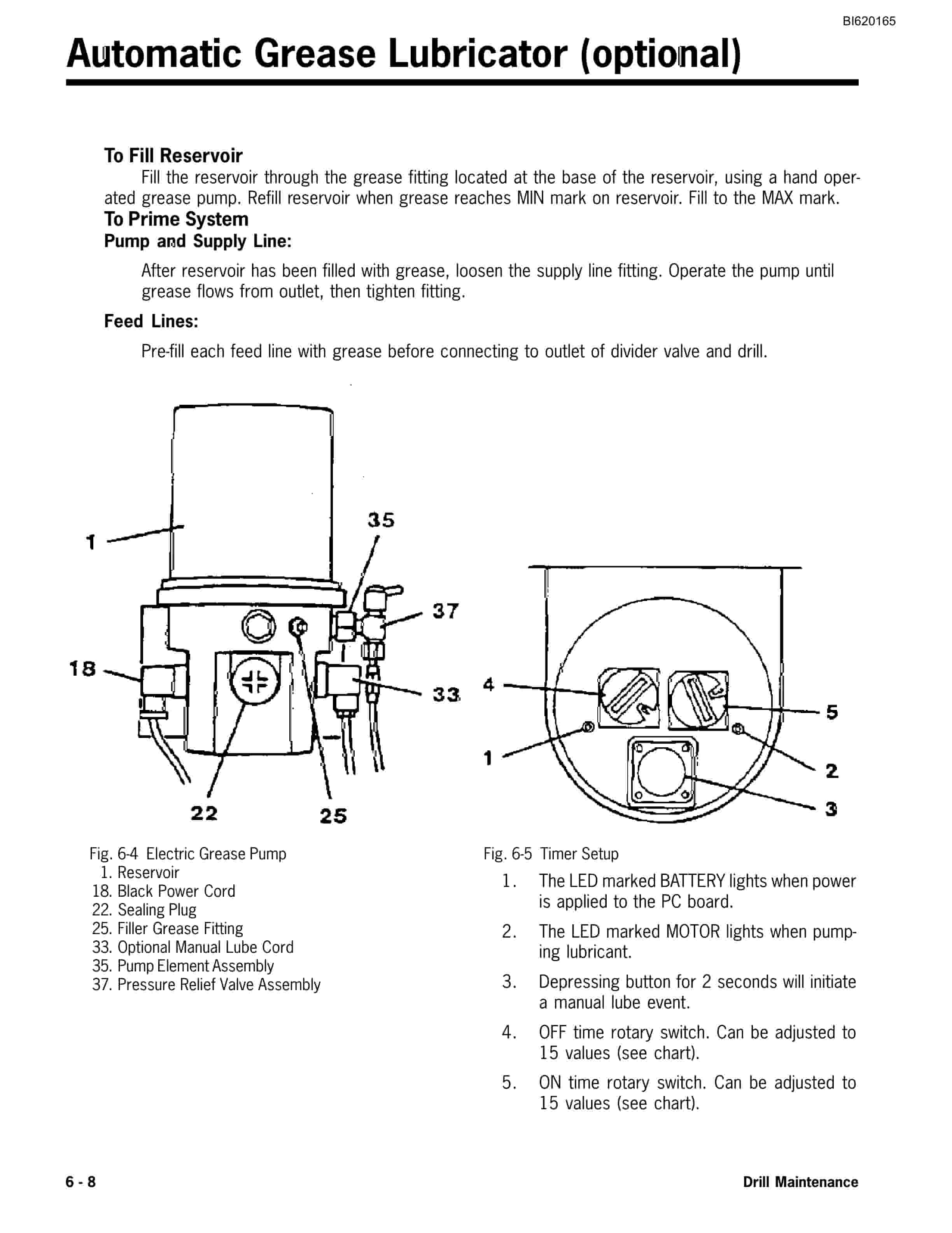
Bucyrus SCH5000 Hydra-Trac Hydraulic Track Drill Technical Manual BI620165
$30.00
- Type Of Manual: Technical Manual
- Manual ID: BI620165
- Number of Pages: 143
- Size: 7.9MB
- Format: PDF
Product details
-
Model List:
- SCH5000 Hydra-Trac Hydraulic Track Drill
- 1. SCH5000 Operator 3rd Ed.pdf
- 1.1. Parts Ordering Product Support
- 1.2. Introduction
- 1.2.1. General Information
- 1.2.2. Table of Contents
- 1.3. Section 1 SAFETY
- 1.3.1. Overview of Potential Hazards
- 1.3.2. Safety Instructions
- 1.4. Section 2 Operator Controls
- 1.4.1. Tram/Drill Positioning Controls
- 1.4.2. Instrument Panel – Non-Cab with 3306 Engine
- 1.4.3. Instrument Panel – Non-Cab with C-10/11 Engine
- 1.4.4. Drilling Controls – Non-Cab Machine
- 1.4.5. Instrument Panel – Cab Machine
- 1.4.6. Drilling Controls – Cab Machine
- 1.4.7. Tramming Controls – Cab Machine
- 1.4.8. Drill Positioning Controls – Cab Machine
- 1.4.9. Air Ride Seat
- 1.5. Section 3 Operating Procedures
- 1.5.1. Personal Safety
- 1.5.2. Walk-Around Checks
- 1.5.3. Pre-Start Checklist
- 1.5.3.1. Engine and Gearcases
- 1.5.3.2. Pneumatic System
- 1.5.3.3. Feed Table Pivot Pin
- 1.5.3.4. Boom, Feed and Drill
- 1.5.3.5. Drill Accumulators
- 1.5.4. Daily Maintenance
- 1.5.5. Mounting Dismounting Machine
- 1.5.6. Start-Up Procedure
- 1.5.6.1. Cold Weather Starting
- 1.5.7. Tramming-Preliminary Checks and Warnings
- 1.5.8. Tramming from Operators Cab
- 1.5.9. Tramming from Tram Station
- 1.5.10. Shutdown Procedure
- 1.6. Section 4 Drilling Procedures
- 1.6.1. Loading Drill Steel
- 1.6.2. Drill Positioning Procedure
- 1.6.3. Drilling Procedure
- 1.6.3.1. Collaring The Hole
- 1.6.3.2. Collaring Circuit
- 1.6.3.3. Normal Drilling
- 1.6.4. Drilling Practices
- 1.6.4.1. Collaring
- 1.6.4.2. Hole Deviation
- 1.6.4.3. Feed Pressure
- 1.6.4.4. Drill Pressures
- 1.6.4.5. Adjusting Drill Pressure and Monitoring the Machine
- 1.6.4.6. Plugged Bit and Stuck Drill Steel
- 1.6.5. Anti-Jam System (optional)
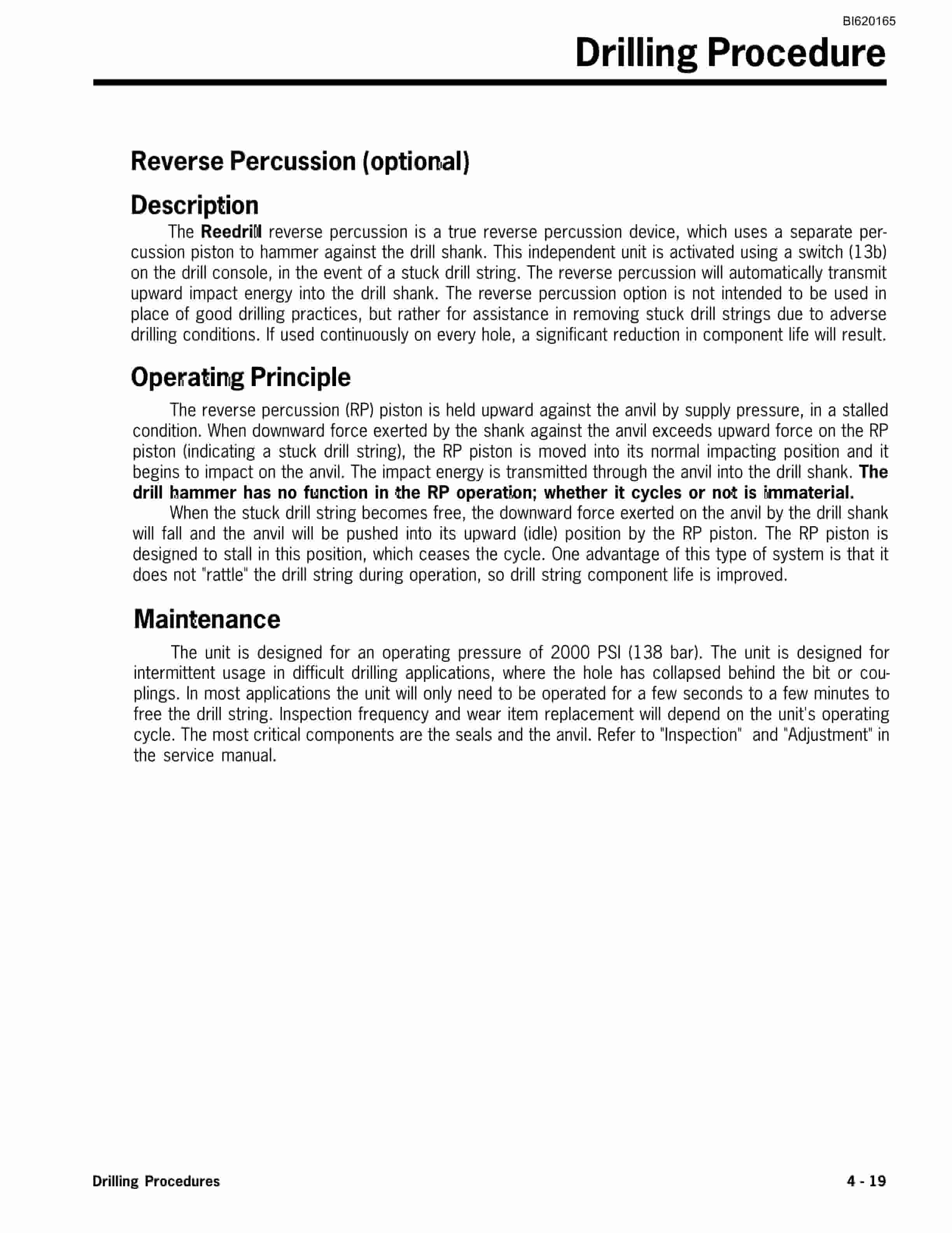
- 1.6.6. Reverse Percussion (optional)
- 1.6.7. Adding and Removing Drill Steel
- 1.6.7.1. Adding Drill Steel
- 1.6.7.2. Removing Drill Steel
- 1.6.8. HPR2 Drill Shank Replacement
- 1.6.9. Indexing the Swing Cylinder
- 1.7. Section 5 Preventive Maintenance
- 1.7.1. Hydraulic Oils for Percussion Drills
- 1.7.2. Lubrication and Inspection
- 1.7.2.1. Engine Oil
- 1.7.3. Bolt Maintenance
- 1.7.4. Bolt Torque Specifications
- 1.7.5. Preventive Maintenance Chart
- 1.7.6. SCH5000 Grease Points
- 1.7.6.1. Drill Centralizer Grease Points
- 1.7.6.2. Feed Feed Drive Grease Points
- 1.7.6.3. Lower Rod Rack Rod Wrench Grease Points
- 1.7.6.4. Rod Rack Driveline Grease Points
- 1.7.6.5. Upper Rod Rack Hose Reel Grease Points
- 1.7.6.6. Feed Table Grease Points
- 1.7.6.7. Positioner (12 Ft. Feed) Grease Points
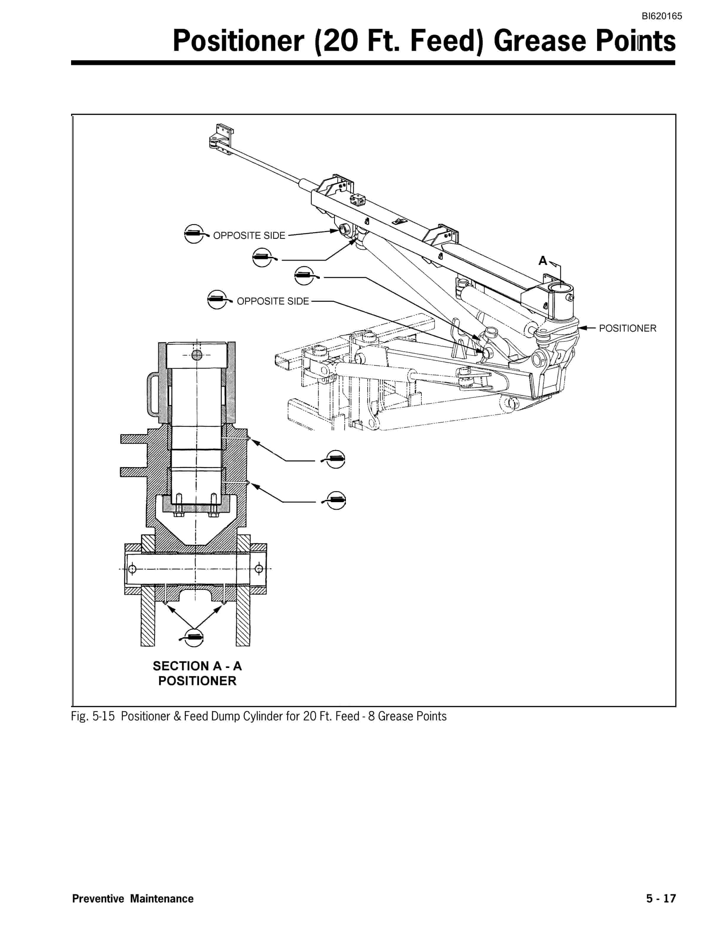
- 1.7.6.8. Positioner (20 Ft. Feed) Grease Points
- 1.7.6.9. Boom Assembly Grease Points
- 1.7.6.10. Drill Console Boom (non-cab) Grease Points
- 1.7.6.11. Cab Mounting Grease Points
- 1.7.6.12. Track Assembly Grease Points
- 1.7.6.13. Ft. Feed Headrest Grease Points
- 1.7.6.14. C-10 C11 Engine Fan Drive Grease Point
- 1.7.7. Maintenance Record
- 1.8. Section 6 Drill Maintenance
- 1.8.1. Charging the Accumulators
- 1.8.1.1. Requirements
- 1.8.1.2. Procedure
- 1.8.2. Checking the Accumulator Charge Pressure
- 1.8.3. Accumulator Charge Kit
- 1.8.4. Lubrication
- 1.8.4.1. Grease Lubrication with a Hand Grease Gun
- 1.8.4.2. Automatic Lubrication
- 1.8.5. Automatic Grease Lubricator (optional)
- 1.9. Section 7 Dust Control
- 1.9.1. WARNING HEALTH HAZARD
- 1.9.2. Dust Collector Assembly
- 1.9.3. Function of Dust Collector
- 1.9.4. Detailed Function of Components
- 1.9.5. Dust Collector Setup
- 1.9.5.1. Initial Start-up and Tuning
- 1.9.5.2. Dust Collector Valve – Adjustment (non-electronic engine)
- 1.9.5.3. Dust Collector Valve – Adjustment (electronic engine)
- 1.9.5.4. Air Pressure Regulator – Adjustment
- 1.9.5.5. Timer – Adjustment
- 1.9.6. Filter Elements
- 1.9.7. Dust Collector Efficiency
- 1.9.8. Operational Variables
- 1.9.9. Fine Tuning
- 1.9.10. Manometer Setup Instructions
- 1.9.11. Timer Installation
- 1.9.12. Control Circuit
- 1.9.13. Fan Removal and Installation
- 1.9.14. Troubleshooting Hints
- 1.9.15. Detergent System
- 1.9.15.1. Description
- 1.9.15.2. Operation
- 1.9.16. Filling The Tank
- 1.9.17. Servicing the Y Strainer
- 1.9.18. Detergent System Freeze Protection
- 1.9.19. Detergent System Piping
- 1.10. Section 8 Glossary
Related products
-
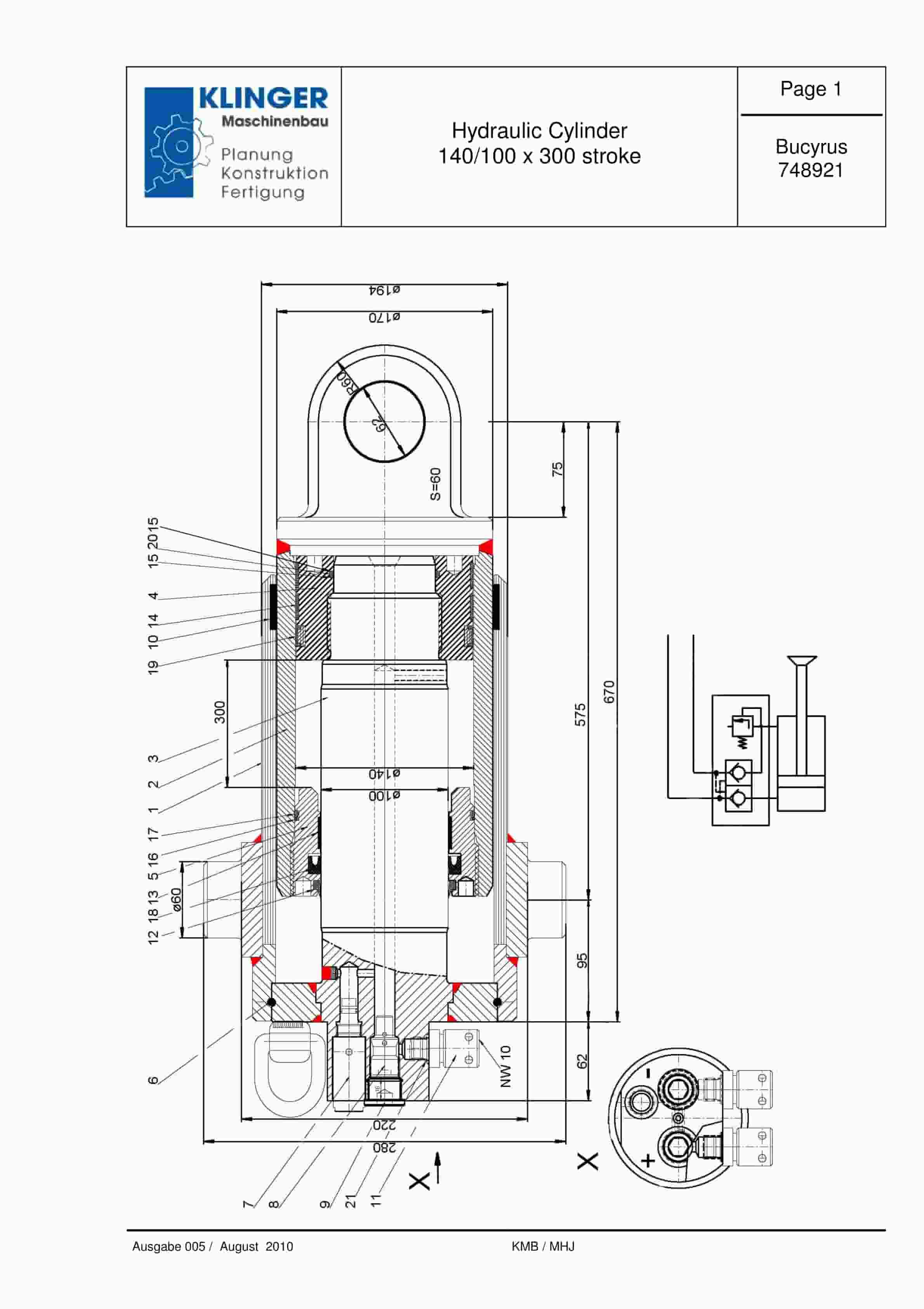
Bucyrus Hydraulic Cylinder 140-100 x 300 Stroke Service Parts List 748921
$30.00 Add to cart -
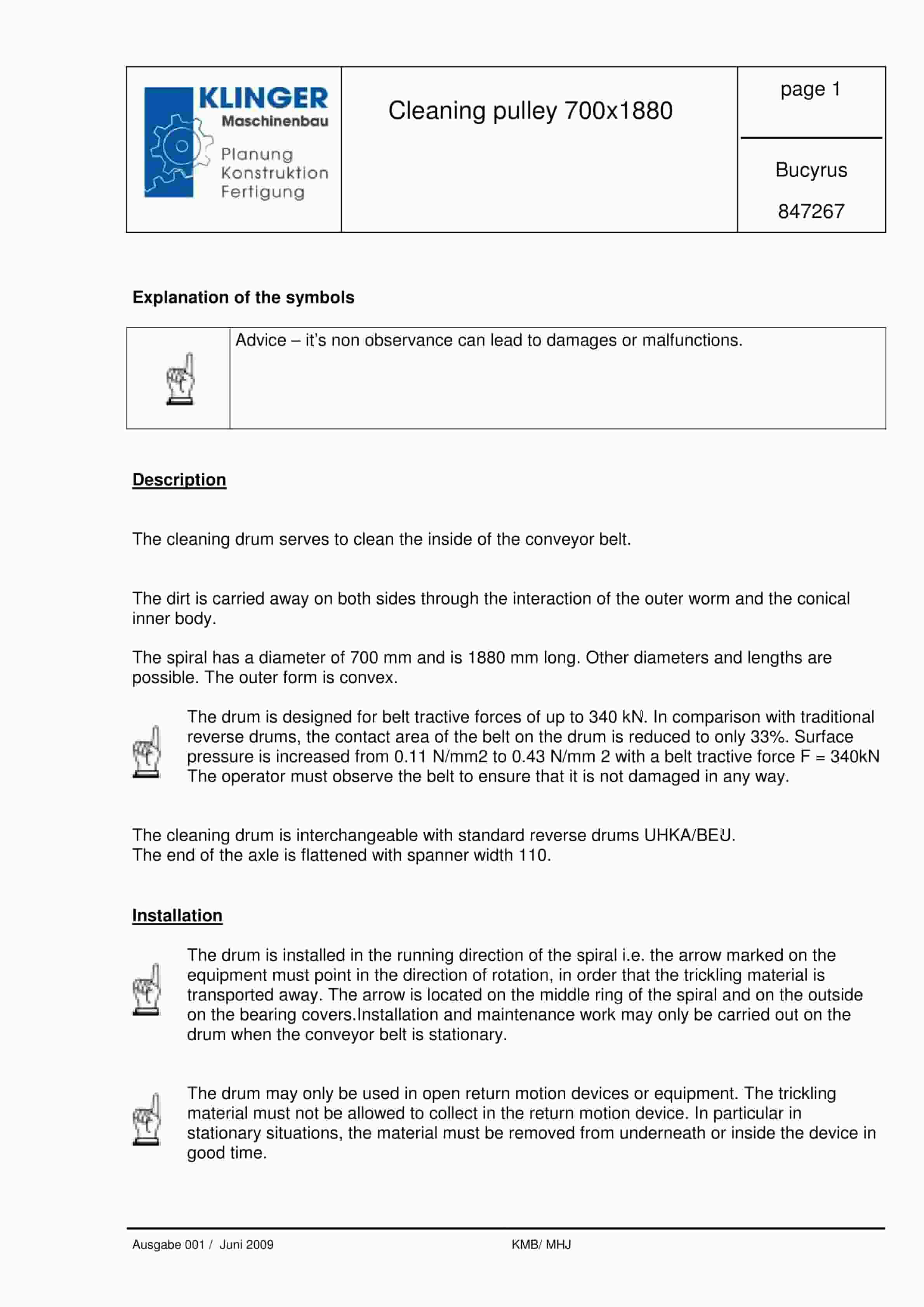
Bucyrus Cleaning Pulley 700 x 1880 Service Parts List 847267
$30.00 Add to cart -
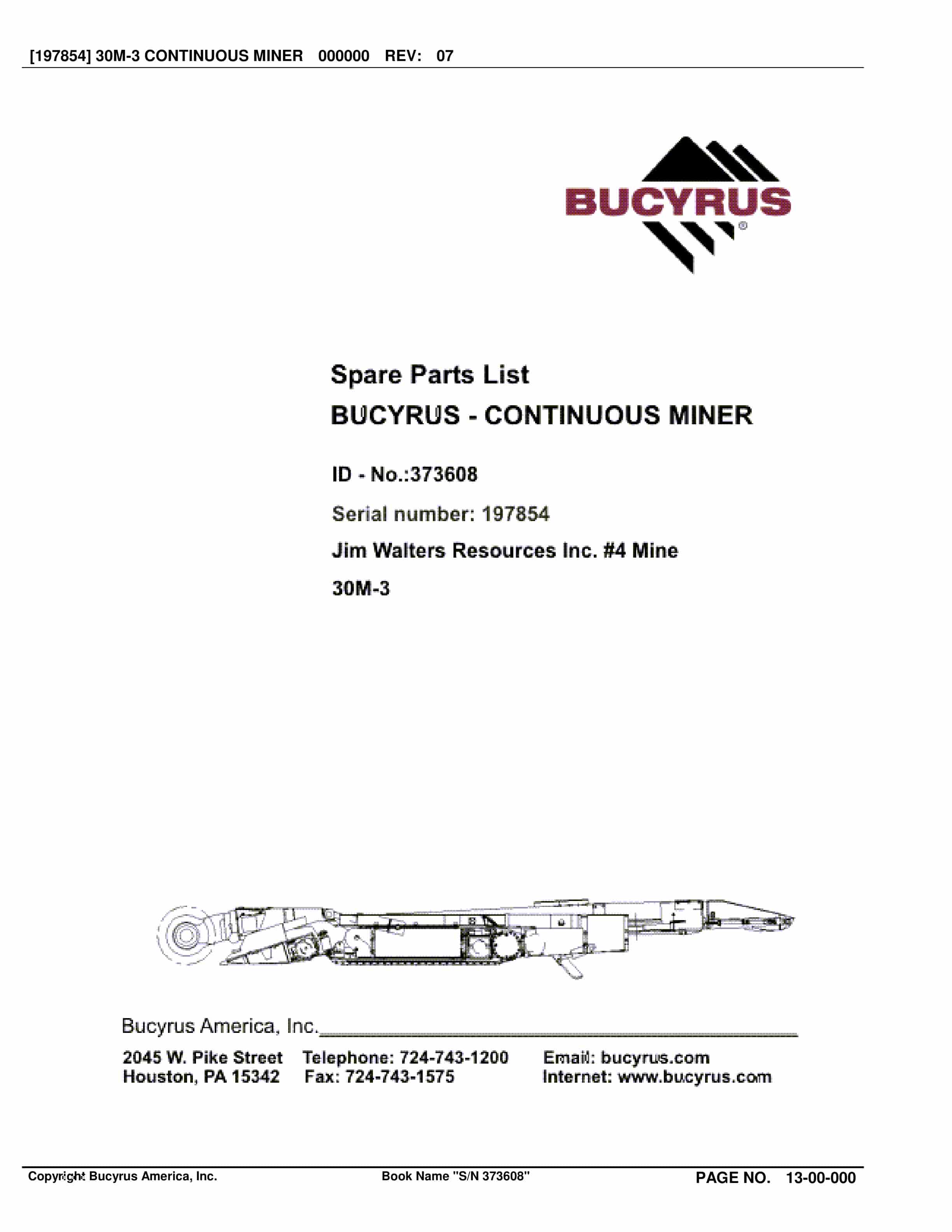
Bucyrus Continuous Miner Spare Parts List 373608
$30.00 Add to cart -
Bucyrus Belt System Spare Parts List 203106
$30.00 Add to cart -
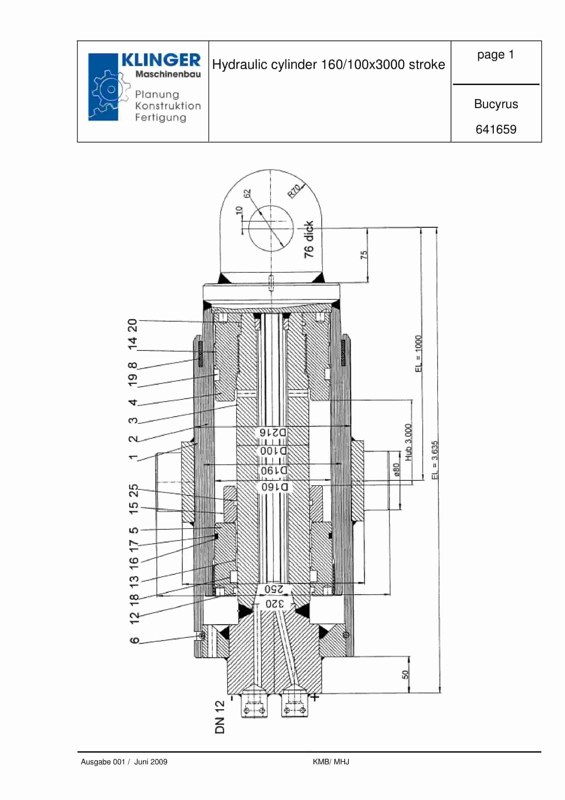
Bucyrus Hydraulic Cylinder 160-100 x 3000 Stroke Service Parts List 641659
$30.00 Add to cart


