

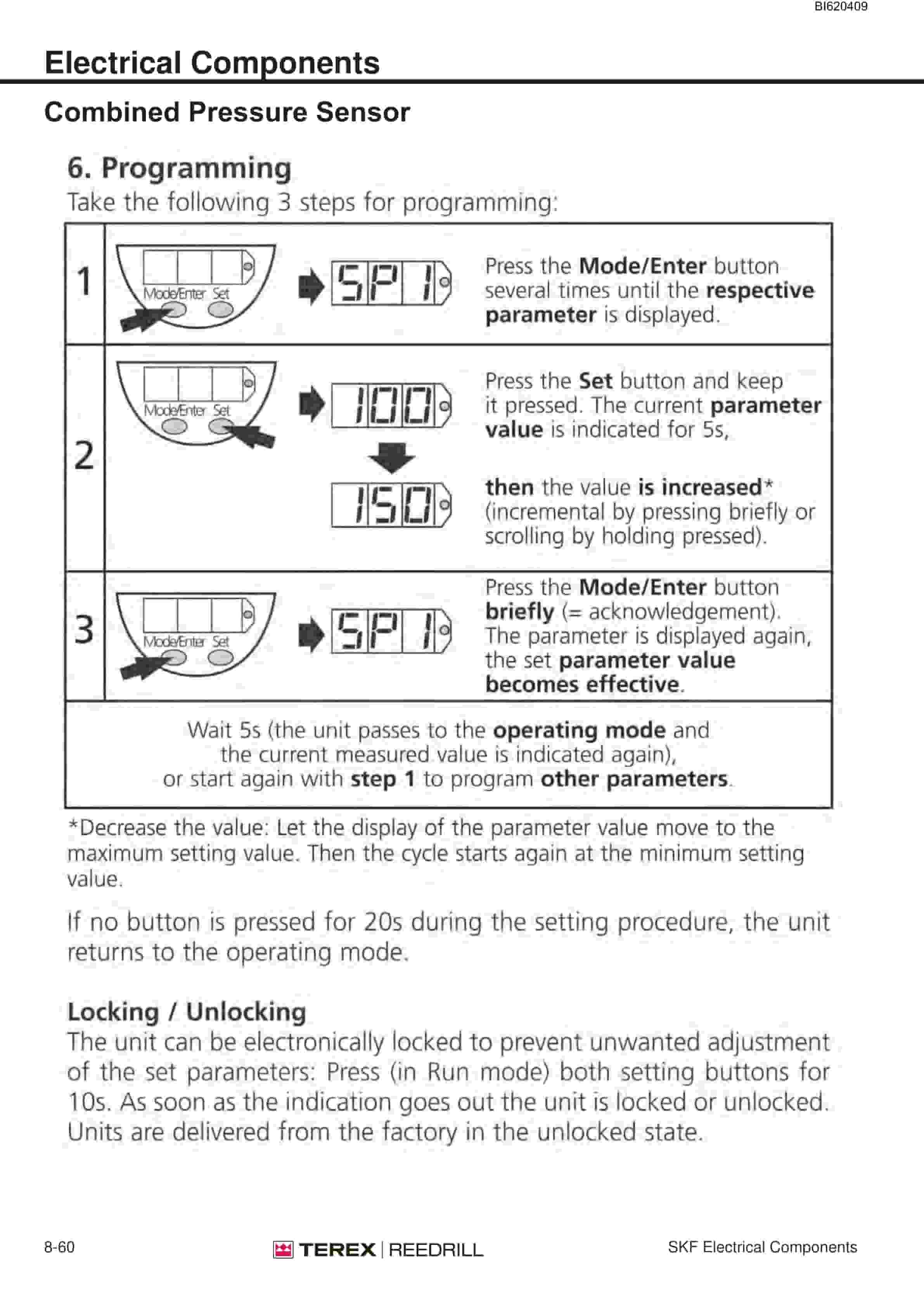
Bucyrus SKF-12 Infinity Blasthole Drill Technical Manual BI620409
$30.00
- Type Of Manual: Technical Manual
- Manual ID: BI620409
- Number of Pages: 795
- Size: 51.0MB
- Format: PDF
Product details
-
Model List:
- SKF-12 Infinity Blasthole Drill
- 1. SKF-12_1D68E74_ServiceManual.pdf
- 1.1. ServiceManual
- 1.1.1. Parts Ordering and Product Support
- 1.1.2. Safety Information
- 1.1.3. Product Description
- 1.1.4. SKF-12 Component Locator
- 1.1.5. Table of Contents
- 1.1.6. Section 1 – Safety
- 1.1.6.1. Personal Protective Equipment
- 1.1.6.2. Electrical Contact
- 1.1.6.3. Overhead and Buried Utilities
- 1.1.6.4. Clearances from OverheadHigh Voltage Lines
- 1.1.6.5. Contaminated Air
- 1.1.6.6. Machine Stability
- 1.1.6.7. Moving and Rotating Parts
- 1.1.6.8. High Pressure Air or Fluid
- 1.1.6.9. Before Operation
- 1.1.6.10. During Operation
- 1.1.6.11. Maintenance
- 1.1.6.12. General Locator
- 1.1.7. Section 2 – Operators Cab/Controls
- 1.1.7.1. Graphic Symbol Legend
- 1.1.7.2. Warning Decals
- 1.1.7.3. Operator Control Panel
- 1.1.7.4. System Pressure Guage Panel
- 1.1.7.5. Switch Panel
- 1.1.7.6. Switches / Diagnostic Control Panel
- 1.1.7.7. Cab Heater
- 1.1.7.7.1. Cab Heater Fault Isolation
- 1.1.7.8. AC/ Heater/Pressurizer Unit
- 1.1.8. Section 3 – Main Frame/Crawlers
- 1.1.8.1. Leveling Jacks
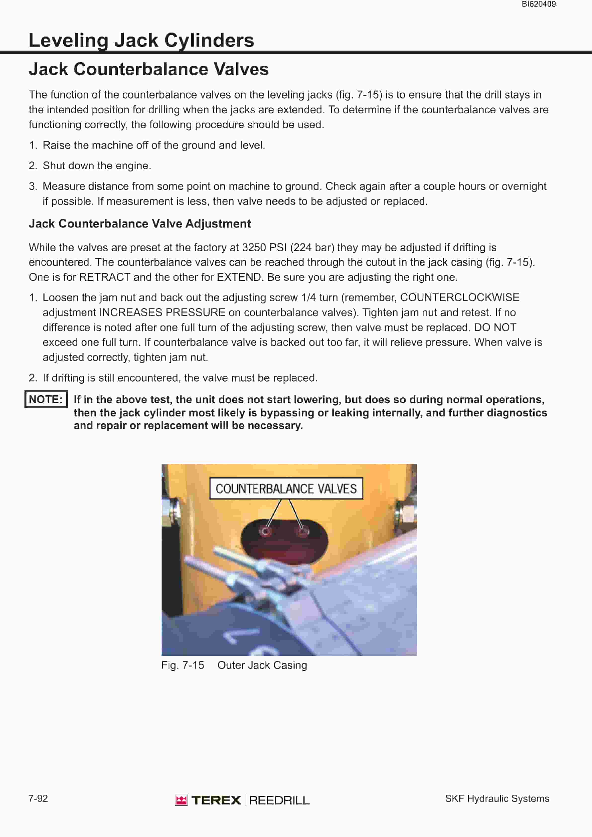
- 1.1.8.1.1. Leveling Jack Cylinders
- 1.1.8.1.2. Lubricating Jack Casings
- 1.1.8.2. Mast Elevating Cylinders
- 1.1.8.2.1. Removal
- 1.1.8.2.2. Replace
- 1.1.8.3. Crawler Assembly
- 1.1.8.4. Crawler Component Repair
- 1.1.8.5. Metric Bolt Torque Specifications
- 1.1.8.6. Track Maintenance
- 1.1.8.6.1. Before Operating the Machine
- 1.1.8.6.2. General Maintenance
- 1.1.8.7. Track Tension Adjustment
- 1.1.8.8. Track Chain
- 1.1.8.8.1. Separate Track Chain Assembly
- 1.1.8.8.2. Track Link – Repair Replace
- 1.1.8.8.3. Track Link – Description
- 1.1.8.9. Track Shoes
- 1.1.8.9.1. Track Link Position
- 1.1.8.9.2. Track Shoe – Mounting to Track Chain
- 1.1.8.10. Track Shoe Bolt Torque (Direct Torque Method)
- 1.1.8.11. Track Shoe Bolt Torque (Torque Turn Method)
- 1.1.8.12. Track Assembly
- 1.1.8.12.1. Track Chain with Shoes
- 1.1.8.12.2. Track Chain Shoe – Assembly Installation
- 1.1.8.13. Final Drive
- 1.1.8.13.1. Final Drive – General Description
- 1.1.8.13.2. Removal from Track Frame
- 1.1.8.13.3. Installation into Track Frame
- 1.1.8.13.4. Oil Check / Change
- 1.1.8.14. Final Drive Oil
- 1.1.8.14.1. Specifications
- 1.1.8.14.2. Recommended Oils
- 1.1.8.15. Final Drive Assembly
- 1.1.8.15.1. Parking Brake – Description
- 1.1.8.15.2. Parking Brake – Removal Installation
- 1.1.8.15.3. Towing Procedure – Gear Drive Disconnect
- 1.1.8.15.4. OK Sevice Manual
- 1.1.8.16. Idler Unit
- 1.1.8.16.1. General Description
- 1.1.8.16.2. Removal and Disassembly
- 1.1.8.16.3. Assembly and Installation
- 1.1.8.17. Track Tension Unit
- 1.1.8.17.1. Installation
- 1.1.8.18. Track Rollers
- 1.1.8.18.1. General Description
- 1.1.8.18.2. Removal Disassembly
- 1.1.8.18.3. Track Roller – Assembly
- 1.1.8.18.4. Track Roller – Test and Install
- 1.1.8.19. Support Rollers
- 1.1.8.19.1. General Description
- 1.1.8.19.2. Support Roller Assembly
- 1.1.8.19.3. Removal Disassembly
- 1.1.8.19.4. Support Roller – Assembly
- 1.1.9. Section 4 – Engine/Drive Train/Compressor
- 1.1.9.1. Engine and Drive Train Service Procedures
- 1.1.9.1.1. Power Train
- 1.1.9.1.2. Engine Service Procedures
- 1.1.9.1.3. Caterpillar 3412E Engine
- 1.1.9.1.4. Engine and Compressor Air Cleaner Service
- 1.1.9.2. Flexible Drive Coupling
- 1.1.9.2.1. Flexible Drive Coupling Service
- 1.1.9.2.2. Removal
- 1.1.9.2.3. Installation
- 1.1.9.3. Pump Drive
- 1.1.9.3.1. Pump Drive Assembly – Removal and Replacement
- 1.1.9.3.2. Pump Drive Gearbox – Repair
- 1.1.9.4. Hydraulic Pumps
- 1.1.9.4.1. Hydraulic Pump Identification – SKF-12
- 1.1.9.5. Compressor Service Procedures
- 1.1.9.5.1. Compressor Drive Coupling – Removal and Replacement
- 1.1.9.5.2. Taper-Loc Bushing Installation
- 1.1.9.5.3. Before Installation Start-Up of New or Rebuilt Compressor
- 1.1.9.5.4. Compressor Unit – Installation
- 1.1.9.6. High Pressure Compressor
- 1.1.9.6.1. Section 1 Safety
- 1.1.9.6.2. Section 2 Description
- 1.1.9.7. Compressor Fluid Circuit
- 1.1.9.8. Compressor Condensation Table
- 1.1.9.8.1. H Relative Humidity
- 1.1.9.9. Compressor Functional Description
- 1.1.9.9.1. Start Mode – 0 to 160 psig
- 1.1.9.9.2. Normal Operation – 160 to 350 psig
- 1.1.9.9.3. Modulating mode – 350 to 360 psig
- 1.1.9.9.4. Unload mode – Above 360 psig
- 1.1.9.9.5. Shutdown Mode
- 1.1.9.9.6. Section 3 Operation
- 1.1.9.10. Compressor Operation
- 1.1.9.10.1. Compressor Air Circuits
- 1.1.9.10.2. Regulator Set Up
- 1.1.9.10.3. Section 4 General Maintenance
- 1.1.9.11. Conpressor Maintanence
- 1.1.9.11.1. Inspection and Preparation For Seal Assembly
- 1.1.9.11.2. Installation Of The Seal Seat
- 1.1.9.11.3. Installation Of The Seal Assembly
- 1.1.9.11.4. Installation of Dust Shield, Gasket and V-Rings
- 1.1.9.11.5. Interstage Tube
- 1.1.9.11.6. Discharge Check Valve
- 1.1.9.11.7. Separator/Receiver Tank
- 1.1.9.11.8. Minimum pressure / check valve
- 1.1.9.11.9. Scavenge Line
- 1.1.9.11.10. Return line strainer
- 1.1.9.11.11. Separator fluid return line sight glass
- 1.1.9.11.12. Scavenge Line Orifice
- 1.1.9.11.13. Compressor Discharge Temperature Switches, Senders andGauges
- 1.1.9.11.14. Thermal/Bypass Valve
- 1.1.9.11.15. Thermal Bypass valve maintenance
- 1.1.9.11.16. Compressor Fluid Filter
- 1.1.9.11.17. Changing Filter Elements
- 1.1.9.11.18. Fluid Stop Valve
- 1.1.9.11.19. Inlet Valve
- 1.1.9.11.20. Relieving Regulators
- 1.1.9.11.21. High and Low Pressure Relieving Regulator Maintenance
- 1.1.9.11.22. Reducing Regulators
- 1.1.9.11.23. Reducing Regulator Maintenance
- 1.1.9.11.24. System Blowdown Valve
- 1.1.9.11.25. System Blowdown Maintenance
- 1.1.9.11.26. Running Blowdown Valve
- 1.1.9.11.27. Running Blowdown Maintenance
- 1.1.9.11.28. Moisture Separator Maintenance
- 1.1.9.11.29. Troubleshooting
- 1.1.9.11.30. Spare Parts List
- 1.1.9.12. Fan / Oil Cooler Piping
- 1.1.9.13. Fan and Motor Installation
- 1.1.9.14. Radiator / Oil Cooler Repair
- 1.1.9.15. Section 5 – Dust Control Systems
- 1.1.9.15.1. Dust Control System Functions
- 1.1.9.15.2. Water Injection Circuit
- 1.1.9.15.3. Dust Collector/Water Injection Circuit
- 1.1.9.15.4. Water Pump
- 1.1.9.15.5. Water Pump Motor
- 1.1.9.16. Section 6 – Mast/Rotary Drive/Pipe Rack
- 1.1.9.16.1. Meter Mast Assembly
- 1.1.9.16.2. Cable Tensioning Assembly
- 1.1.9.16.3. Feed Cylinder – Removal and Installation
- 1.1.9.16.4. SKF-12 Feed Cylinder
- 1.1.9.16.5. Hoist/Pulldown Cable Adjustment
- 1.1.9.16.6. Hoist/Pulldown Cable Replacement
- 1.1.9.16.7. Rotary Head Guide Alignment
- 1.1.9.16.8. Rotary Drive Assembly
- 1.1.9.16.9. Rotary Drive Motor
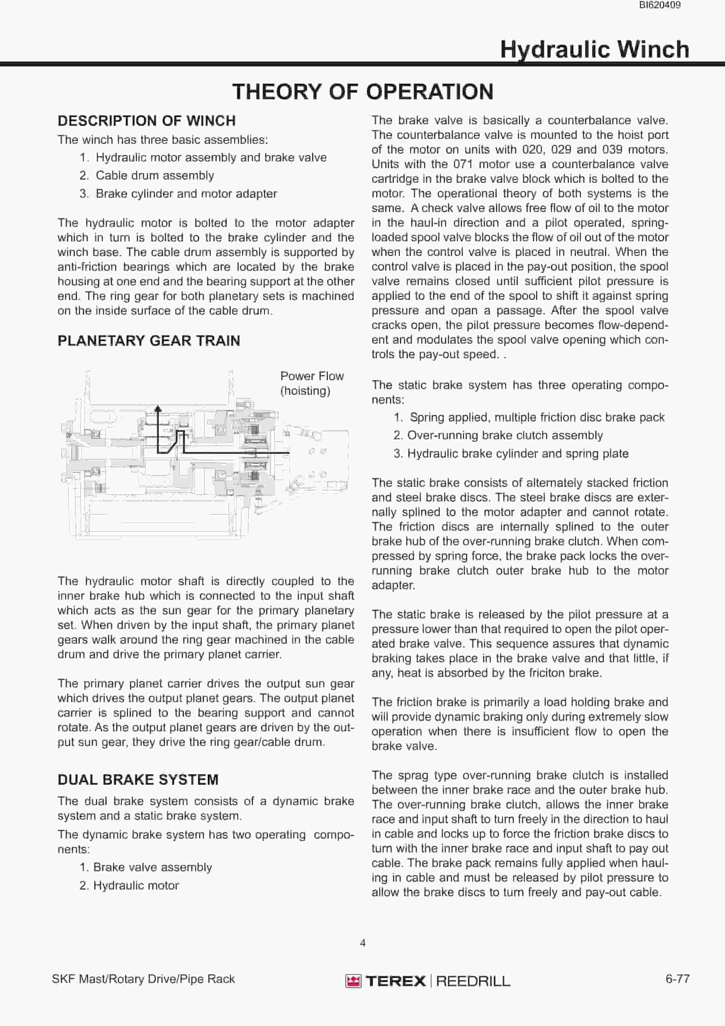
- 1.1.9.16.10. Winch Assembly
- 1.1.9.16.11. Hydraulic Winch
- 1.1.9.16.12. Deck Wrench
- 1.1.9.16.13. HOBO Wrench
- 1.1.9.16.14. Pipe Positioner
- 1.1.9.16.15. Carousel Pipe Rack
- 1.1.9.17. Section 7 – Hydraulic Systems
- 1.1.9.17.1. Hydraulic Symbols
- 1.1.9.17.2. Hydraulic Tank
- 1.1.9.17.3. Hydraulic System
- 1.1.9.17.4. Pressure Setting Sequence
- 1.1.9.17.5. Main Return and Case Drain Filter
- 1.1.9.17.6. Main Hydraulic Pumps
- 1.1.9.17.7. Right Track, Left Track/Rotation Pumps
- 1.1.9.17.8. Hydraulic Piston Pumps – Maintenance
- 1.1.9.17.9. Hydraulic Piston Pumps – Troubleshooting
- 1.1.9.17.10. Charge Circuit
- 1.1.9.17.11. Loop Filters
- 1.1.9.17.12. Diverter Valve
- 1.1.9.17.13. Hydraulic Feed and Rotation Circuits
- 1.1.9.17.14. Drill/Tram Control Circuit
- 1.1.9.17.15. Rotary Drive Gearbox Motor
- 1.1.9.17.16. Fan and Auxiliary Pump Circuit
- 1.1.9.17.17. Hydraulic Pumps
- 1.1.9.17.18. New or Rebuilt Hydraulic Pump – Start-Up
- 1.1.9.17.19. Auxiliary Functions/Fan Circuit
- 1.1.9.17.20. Cooler Fan Circuit
- 1.1.9.17.21. Cooler Fan Motor
- 1.1.9.17.22. Jack and Mast Elevate Circuit
- 1.1.9.17.23. Mast Elevating Cylinders
- 1.1.9.17.24. Leveling Jack Cylinders
- 1.1.9.17.25. Auxiliary Functions/6 Bank Valve
- 1.1.9.17.26. Hydraulic Operated Breakout Wrench (HOBO)
- 1.1.9.17.27. Carousel Rotate Motor
- 1.1.9.17.28. Pilot Control Manifold
- 1.1.9.17.29. Hydraulic Gear Pumps
- 1.1.9.17.30. Dust Collector/Water Injection Circuit
- 1.1.9.17.31. Hydraulic Cylinder Repair
- 1.1.9.18. Section 8 – Electrical Components
- 1.1.9.18.1. Electrical Symbols
- 1.1.9.18.2. Welding Precautions
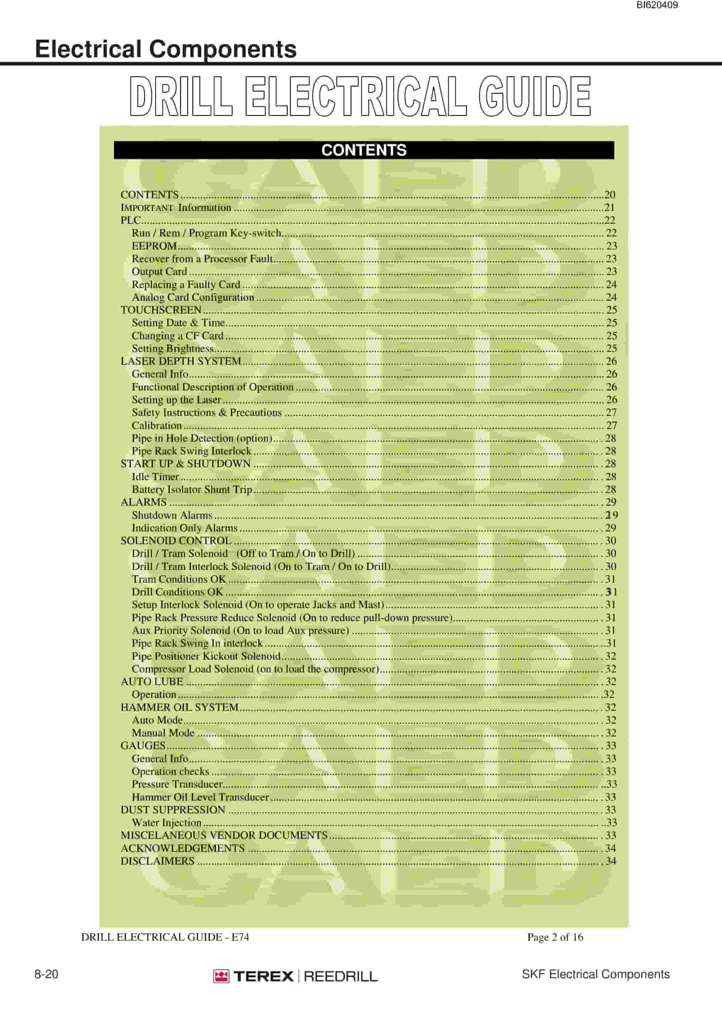
- 1.1.9.18.3. Electrical Components
- 1.1.9.19. Section 9 – Lubrication and Preventative Maintenance
- 1.1.9.19.1. General Locator – SKF-12
- 1.1.9.19.2. Lubrication And Preventative Maintenance
- 1.1.9.19.3. Lubrication And Maintenance Chart
- 1.1.9.19.4. Lubricant Specifi cations
- 1.1.9.19.5. Preventive Maintenance
- 1.1.9.19.6. Torque Values for Standard Fasteners
- 1.1.9.19.7. Torque Values for Split Flange Connections
- 1.1.9.19.8. Torque Values for Hydraulic Tubes Fittings
- 1.1.9.19.9. Section 10 – Optional Equipment
Related products
-
Bucyrus Continuous Miner Spare Parts List 907783
$30.00 Add to cart -
Bucyrus Continuous Miner Spare Parts List 907782
$30.00 Add to cart -
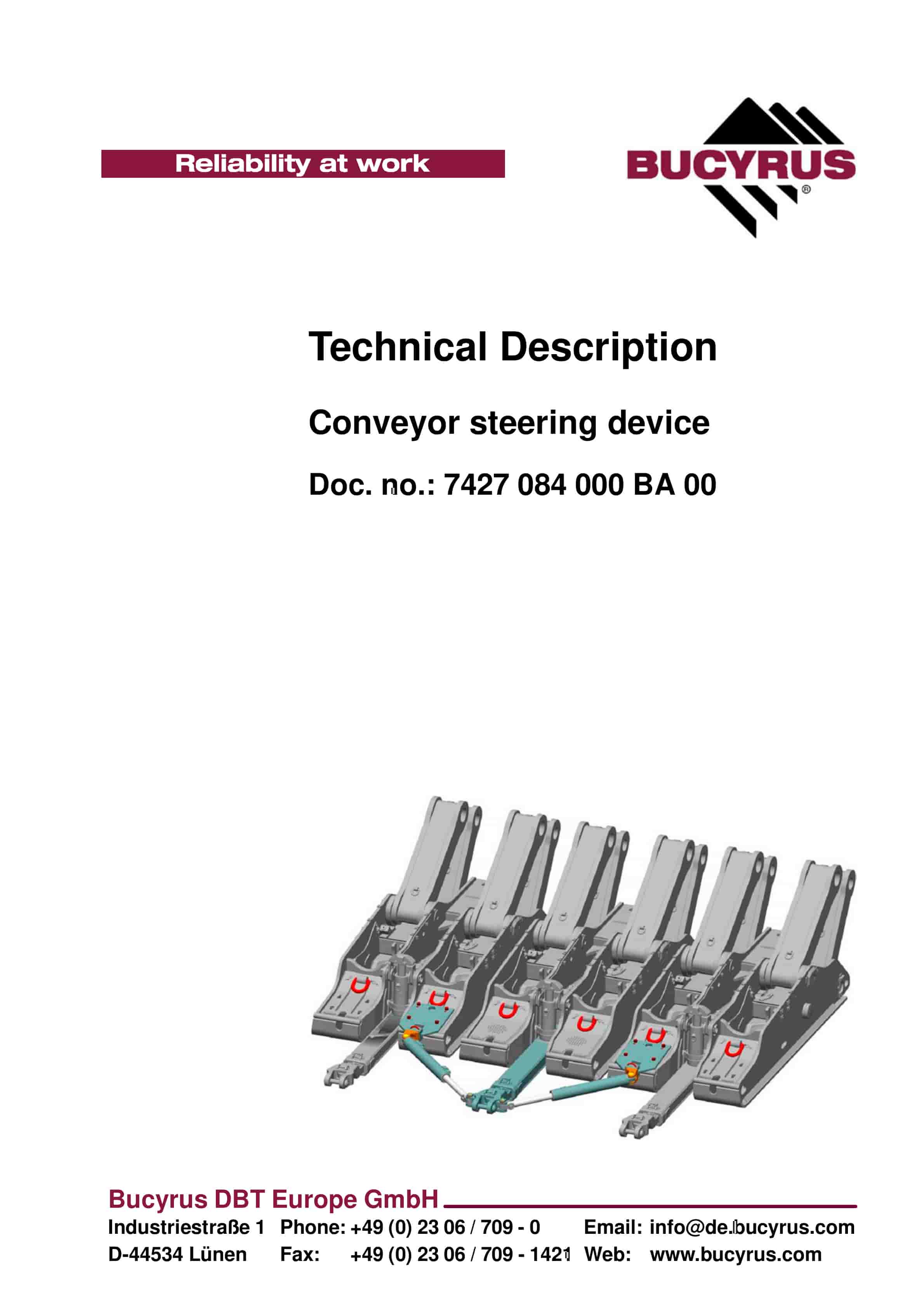
Bucyrus Conveyor Steering Device Technical Description 7427 084 000 BA 00
$30.00 Add to cart -
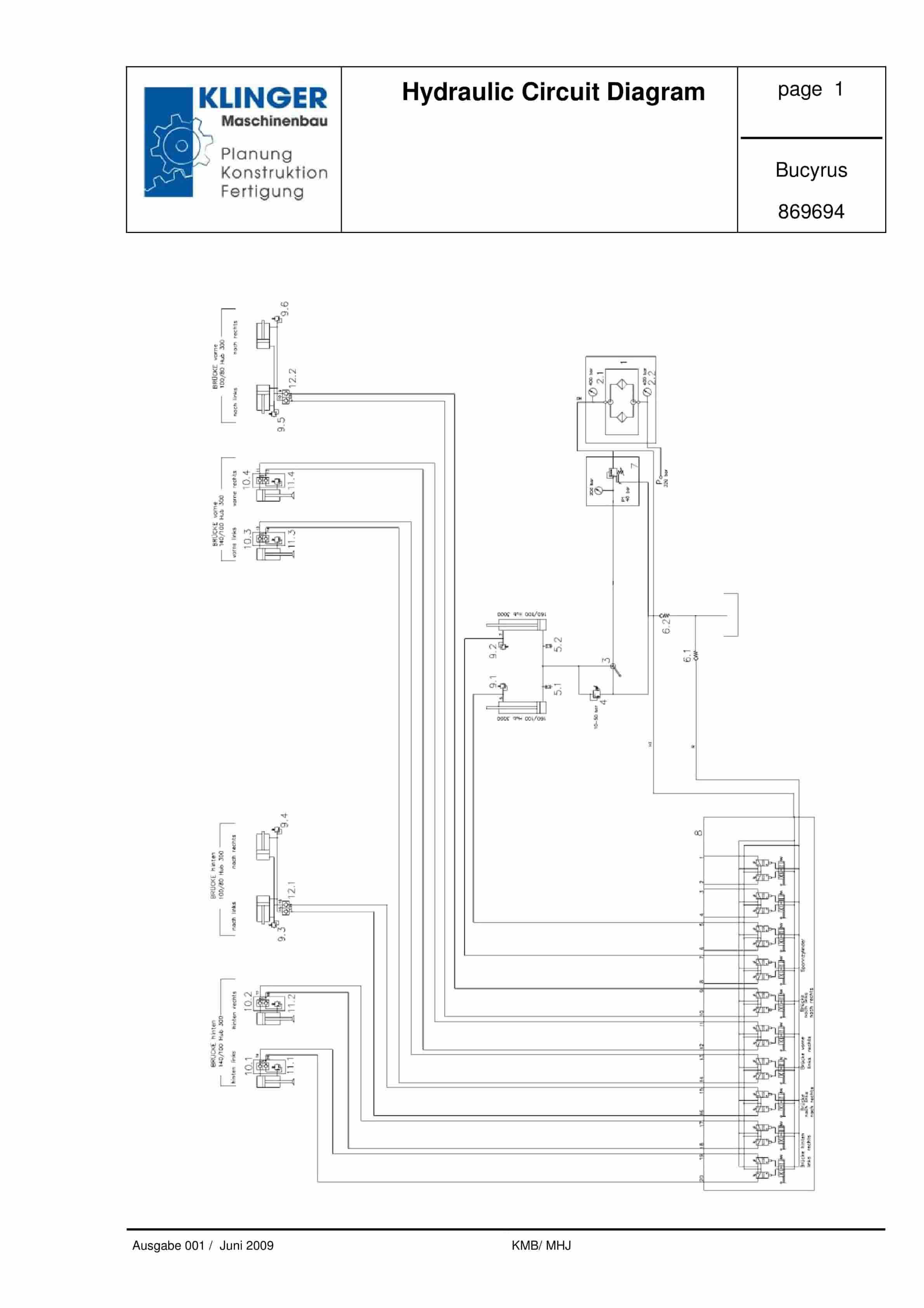
Bucyrus Hydraulic Circuit Diagram Service Parts List 869694
$30.00 Add to cart -
Bucyrus Conveyor Steering Device Technical Description 7427 078 000 BA 00
$30.00 Add to cart


