

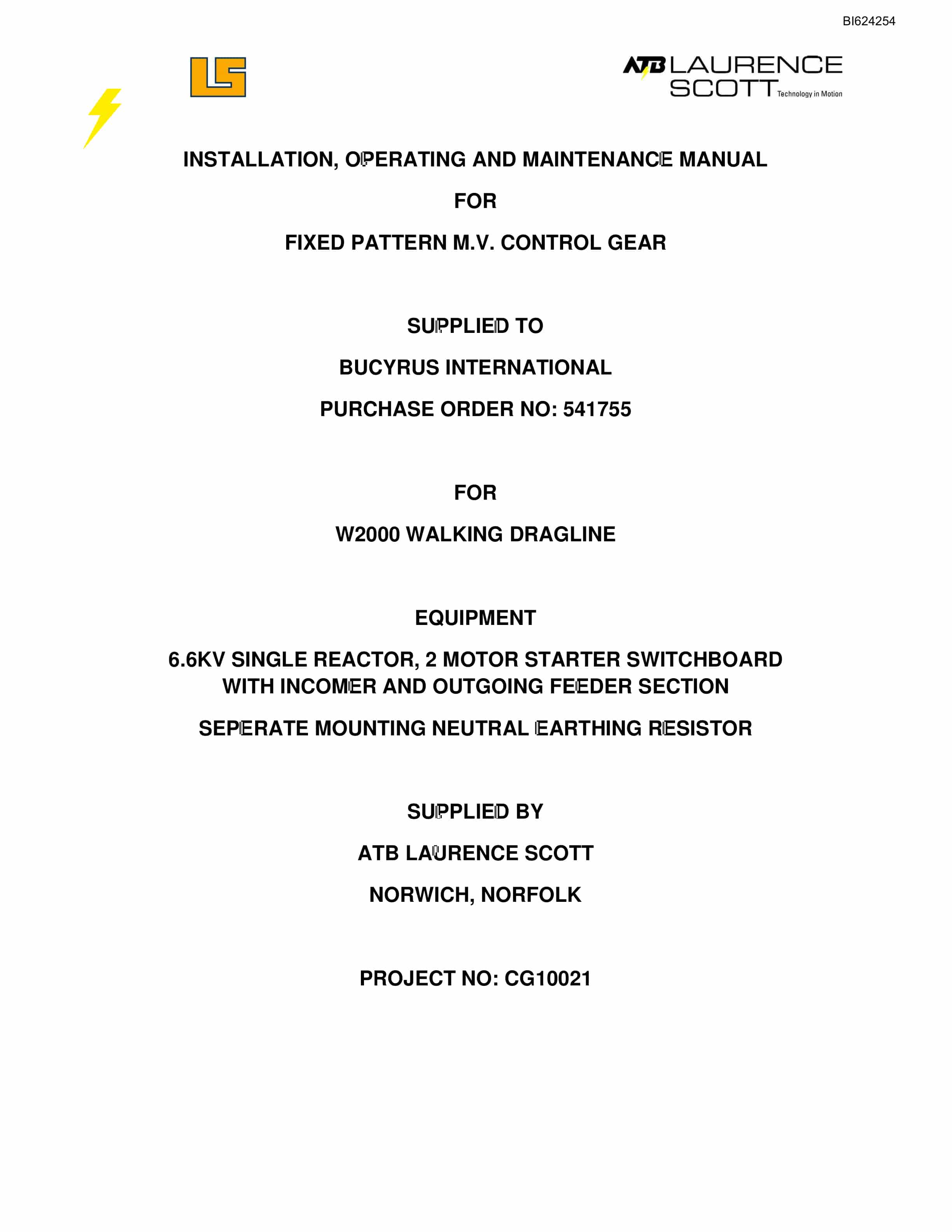
Bucyrus W2000 Walking Dragline Installation, Operating And Maintenance Manual BI624254
$30.00
- Type Of Manual: Installation, Operating And Maintenance Manual
- Manual ID: BI624254
- Number of Pages: 479
- Size: 19.6MB
- Format: PDF
Product details
-
Model List:
- W2000 Walking Dragline
- 1. Section 2.pdf
- 1.1. Model D.pdf
- 1.1.1. TeSys control relays
- 1.1.1.1. Model d control relays
- 1.1.1.1.1. Characteristics
- 1.1.1.1.2. References
- 1.1.1.1.3. Dimensions,mounting
- 1.1.1.1.4. Schemes
- 1.2. an-bu.pdf
- 1.2.1. Introduction
- 1.2.1.1. Ordering
- 1.2.1.1.1. General Overview
- 1.2.1.1.2. Ordering
- 1.2.1.1.3. Accessories
- 1.2.1.1.4. Firmware History
- 1.2.1.1.5. PC Program (Software) History
- 1.2.1.1.6. Relay Functional Summary
- 1.2.1.1.7. Relay Label Definition
- 1.2.2. Product Description
- 1.2.2.1. Overview
- 1.2.2.1.1. Guideform Specifications
- 1.2.2.1.2. Metered Quantities
- 1.2.2.1.3. Protection Features
- 1.2.2.1.4. Additional Features
- 1.2.2.2. Specifications
- 1.2.2.2.1. Inputs
- 1.2.2.2.2. Outputs
- 1.2.2.2.3. Metering
- 1.2.2.2.4. Communications
- 1.2.2.2.5. Protection Elements
- 1.2.2.2.6. Monitoring Elements
- 1.2.2.2.7. Control Elements
- 1.2.2.2.8. Environmental Specifications
- 1.2.2.2.9. Long-term storage
- 1.2.2.2.10. Approvals/Certification
- 1.2.2.2.11. Type Test Standards
- 1.2.2.2.12. Production Tests
- 1.2.3. Installation
- 1.2.3.1. Mechanical Installation
- 1.2.3.1.1. Mechanical Installation
- 1.2.3.2. Terminal Identification
- 1.2.3.2.1. Relay Terminal List
- 1.2.3.2.2. to 369 Relay Conversion Terminal List
- 1.2.3.2.3. MTM-369 Relay Conversion Terminal List
- 1.2.3.2.4. MPM-369 Relay Conversion Terminal List
- 1.2.3.2.5. Terminal Layout
- 1.2.3.3. Electrical Installation
- 1.2.3.3.1. Typical Wiring Diagram
- 1.2.3.3.2. Typical Wiring
- 1.2.3.3.3. Control Power
- 1.2.3.3.4. Phase Current (CT) Inputs
- 1.2.3.3.5. Ground Current Inputs
- 1.2.3.3.6. Zero Sequence Ground CT Placement
- 1.2.3.3.7. Phase Voltage (VT/PT) Inputs
- 1.2.3.3.8. Backspin Voltage Inputs
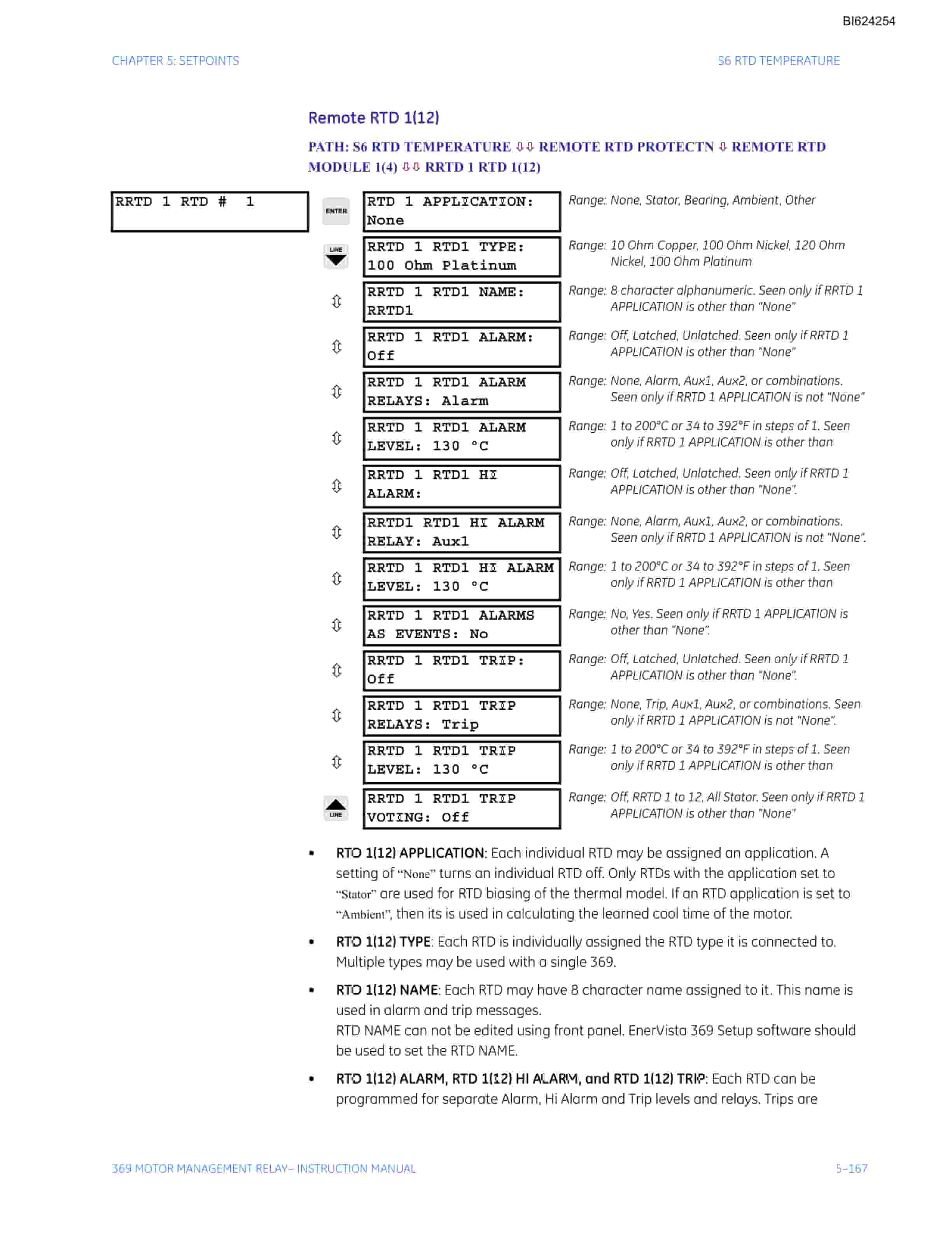
- 1.2.3.3.9. RTD Inputs
- 1.2.3.3.10. Digital Inputs
- 1.2.3.3.11. Analog Outputs
- 1.2.3.3.12. Remote Display
- 1.2.3.3.13. Output Relays
- 1.2.3.3.14. RS485 Communications
- 1.2.3.3.15. Typical Two-Speed (Low Speed/High Speed) Motor Wiring
- 1.2.3.3.16. Typical Motor Forward/Reverse Wiring
- 1.2.3.4. Remote RTD Module (RRTD)
- 1.2.3.4.1. Mechanical Installation
- 1.2.3.4.2. Electrical Installation
- 1.2.3.5. CT Installation
- 1.2.3.5.1. Phase CT Installation
- 1.2.3.5.2. Amp Ground CT Installation
- 1.2.3.5.3. HGF (500.025) Ground CT Installation
- 1.2.4. User Interfaces
- 1.2.4.1. Faceplate Interface
- 1.2.4.1.1. Display
- 1.2.4.1.2. LED Indicators
- 1.2.4.1.3. RS232 Program Port
- 1.2.4.1.4. Keypad
- 1.2.4.1.5. Setpoint Entry
- 1.2.4.2. EnerVista 369 Setup Interface
- 1.2.4.2.1. Hardware and Software Requirements
- 1.2.4.2.2. Installing EnerVista 369 Setup
- 1.2.4.3. Connecting EnerVista 369 Setup to the Relay
- 1.2.4.3.1. Configuring Serial Communications
- 1.2.4.3.2. Using the Quick Connect Feature
- 1.2.4.3.3. Configuring Ethernet Communications
- 1.2.4.3.4. Connecting to the Relay
- 1.2.4.4. Working with Setpoints and Setpoint Files
- 1.2.4.4.1. Engaging a Device
- 1.2.4.4.2. Entering Setpoints
- 1.2.4.4.3. File Support
- 1.2.4.4.4. Using Setpoints Files
- 1.2.4.5. Upgrading Relay Firmware
- 1.2.4.5.1. Description
- 1.2.4.5.2. Saving Setpoints to a File
- 1.2.4.5.3. Loading New Firmware
- 1.2.4.6. Advanced EnerVista 369 Setup Features
- 1.2.4.6.1. Triggered Events
- 1.2.4.6.2. Trending
- 1.2.4.6.3. Waveform Capture (Trace Memory)
- 1.2.4.6.4. Motor Start Data Logger
- 1.2.4.6.5. Data Logger
- 1.2.4.6.6. Motor Health Report
- 1.2.4.6.7. Phasors
- 1.2.4.6.8. Event Recorder
- 1.2.4.6.9. Modbus User Map
- 1.2.4.6.10. Viewing Actual Values
- 1.2.4.7. Using EnerVista Viewpoint with the 369 Relay
- 1.2.4.7.1. Plug and Play Example
- 1.2.5. Setpoints
- 1.2.5.1. Overview
- 1.2.5.1.1. Setpoints Main Menu
- 1.2.5.2. S1 369 Setup
- 1.2.5.2.1. Setpoint Access
- 1.2.5.2.2. Display Preferences
- 1.2.5.2.3. Communications
- 1.2.5.2.4. Real Time Clock
- 1.2.5.2.5. Waveform Capture
- 1.2.5.2.6. Data Logger
- 1.2.5.2.7. Event Records
- 1.2.5.2.8. Message Scratchpad
- 1.2.5.2.9. Default Messages
- 1.2.5.2.10. Clear/Preset Data
- 1.2.5.2.11. Modify Options
- 1.2.5.2.12. Factory Service
- 1.2.5.3. S2 System Setup
- 1.2.5.3.1. Description
- 1.2.5.3.2. CT/VT Setup
- 1.2.5.3.3. Monitoring Setup
- 1.2.5.3.4. Block Functions
- 1.2.5.3.5. Output Relay Setup
- 1.2.5.3.6. Control Functions
- 1.2.5.4. S3 Overload Protection
- 1.2.5.4.1. Description
- 1.2.5.4.2. Thermal Model
- 1.2.5.4.3. Overload Curves
- 1.2.5.4.4. Overload Alarm
- 1.2.5.5. S4 Current Elements
- 1.2.5.5.1. Description
- 1.2.5.5.2. Short Circuit
- 1.2.5.5.3. Mechanical Jam
- 1.2.5.5.4. Undercurrent
- 1.2.5.5.5. Current Unbalance
- 1.2.5.5.6. Ground Fault
- 1.2.5.6. S5 Motor Start/Inhibits
- 1.2.5.6.1. Description
- 1.2.5.6.2. Acceleration Trip
- 1.2.5.6.3. Start Inhibits
- 1.2.5.6.4. Backspin Detection
- 1.2.5.7. S6 RTD Temperature
- 1.2.5.7.1. Description
- 1.2.5.7.2. Local RTD Protection
- 1.2.5.7.3. Remote RTD Protection
- 1.2.5.7.4. Open RTD Alarm
- 1.2.5.7.5. Short/Low Temp RTD Alarm
- 1.2.5.7.6. Loss of RRTD Comms Alarm
- 1.2.5.8. S7 Voltage Elements
- 1.2.5.8.1. Description
- 1.2.5.8.2. Undervoltage
- 1.2.5.8.3. Overvoltage
- 1.2.5.8.4. Phase Reversal
- 1.2.5.8.5. Underfrequency
- 1.2.5.8.6. Overfrequency
- 1.2.5.9. S8 Power Elements
- 1.2.5.9.1. Description
- 1.2.5.9.2. Lead Power Factor
- 1.2.5.9.3. Lag Power Factor
- 1.2.5.9.4. Positive Reactive Power
- 1.2.5.9.5. Negative Reactive Power
- 1.2.5.9.6. Underpower
- 1.2.5.9.7. Reverse Power
- 1.2.5.10. S9 Digital Inputs
- 1.2.5.10.1. Digital Input Functions
- 1.2.5.10.2. Spare Switch
- 1.2.5.10.3. Emergency Restart
- 1.2.5.10.4. Differential Switch
- 1.2.5.10.5. Speed Switch
- 1.2.5.10.6. Remote Reset
- 1.2.5.11. S10 Analog Outputs
- 1.2.5.11.1. Analog Outputs
- 1.2.5.12. S11 369 Testing
- 1.2.5.12.1. Test Output Relays
- 1.2.5.12.2. Test Analog Outputs
- 1.2.5.13. S12 Two-speed Motor
- 1.2.5.13.1. Description
- 1.2.5.13.2. Speed 2 Overload Curves
- 1.2.5.13.3. Speed 2 Undercurrent
- 1.2.5.13.4. Speed 2 Acceleration
- 1.2.6. Actual Values
- 1.2.6.1. Overview
- 1.2.6.1.1. Actual Values Main Menu
- 1.2.6.2. A1 Status
- 1.2.6.2.1. Motor Status
- 1.2.6.2.2. Last Trip Data
- 1.2.6.2.3. Data Logger
- 1.2.6.2.4. Diagnostic Messages
- 1.2.6.2.5. Start Block Status
- 1.2.6.2.6. Digital Input Status
- 1.2.6.2.7. Output Relay Status
- 1.2.6.2.8. Real Time Clock
- 1.2.6.2.9. FieldBus Specification Status
- 1.2.6.3. A2 Metering Data
- 1.2.6.3.1. Current Metering
- 1.2.6.3.2. Voltage Metering
- 1.2.6.3.3. Power Metering
- 1.2.6.3.4. Backspin Metering
- 1.2.6.3.5. Local RTD
- 1.2.6.3.6. Remote RTD
- 1.2.6.3.7. Overall Stator RTD
- 1.2.6.3.8. Demand Metering
- 1.2.6.3.9. Phasors
- 1.2.6.4. A3 Learned Data
- 1.2.6.4.1. Description
- 1.2.6.4.2. Motor Data
- 1.2.6.4.3. Local RTD Maximums
- 1.2.6.4.4. Remote RTD Maximums
- 1.2.6.5. A4 Statistical Data
- 1.2.6.5.1. Trip Counters
- 1.2.6.5.2. Motor Statistics
- 1.2.6.6. A5 Event Record
- 1.2.6.6.1. Event Records
- 1.2.6.6.2. Model Information
- 1.2.6.6.3. Firmware Version
- 1.2.7. Applications
- 1.2.7.1. Comparison
- 1.2.7.1.1. and 269plus Comparison
- 1.2.7.2. FAQs
- 1.2.7.2.1. Frequently Asked Questions (FAQs)
- 1.2.7.3. Dos and Donts
- 1.2.7.3.1. Dos and Donts
- 1.2.7.4. CT Specification and Selection
- 1.2.7.4.1. CT Specification
- 1.2.7.4.2. CT Selection
- 1.2.7.5. Programming Example
- 1.2.7.5.1. Programming Example
- 1.2.7.6. Applications
- 1.2.7.6.1. Motor Status Detection
- 1.2.7.6.2. Selection of Cool Time Constants
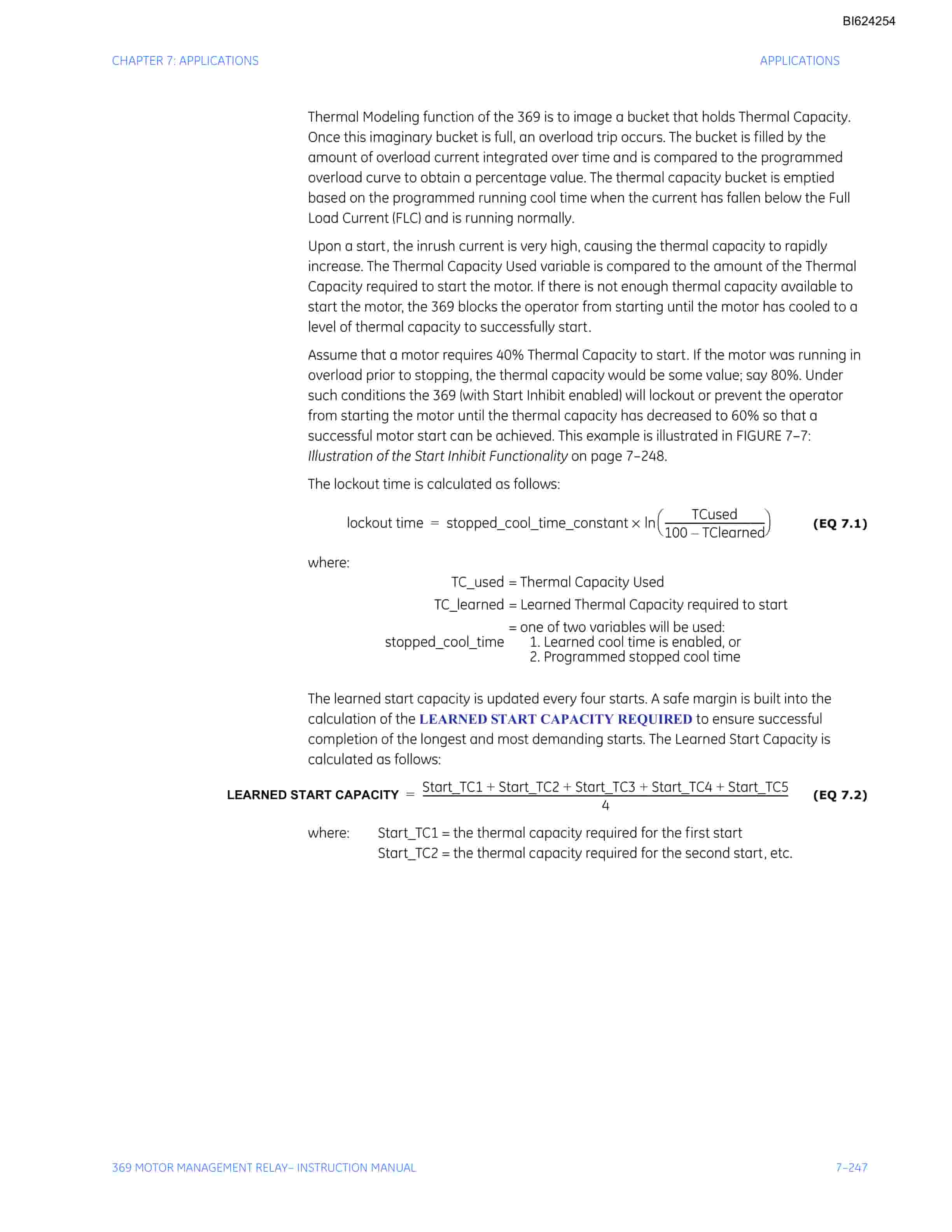
- 1.2.7.6.3. Thermal Model
- 1.2.7.6.4. RTD Bias Feature
- 1.2.7.6.5. Thermal Capacity Used Calculation
- 1.2.7.6.6. Start Inhibit
- 1.2.7.6.7. Two-Phase CT Configuration
- 1.2.7.6.8. Ground Fault Detection on Ungrounded Systems
- 1.2.7.6.9. RTD Circuitry
- 1.2.7.6.10. Reduced RTD Lead Number Application
- 1.2.7.6.11. Two Wire RTD Lead Compensation
- 1.2.7.6.12. Auto Transformer Starter Wiring
- 1.2.8. Testing
- 1.2.8.1. Test Setup
- 1.2.8.1.1. Introduction
- 1.2.8.1.2. Secondary Injection Test Setup
- 1.2.8.2. Hardware Functional Testing
- 1.2.8.2.1. Phase Current Accuracy Test
- 1.2.8.2.2. Voltage Input Accuracy Test
- 1.2.8.2.3. Ground (1 A / 5 A) Accuracy Test
- 1.2.8.2.4. 0.025 Ground Accuracy Test
- 1.2.8.2.5. RTD Accuracy Test
- 1.2.8.2.6. Digital Inputs
- 1.2.8.2.7. Analog Inputs and Outputs
- 1.2.8.2.8. Output Relays
- 1.2.8.3. Additional Functional Testing
- 1.2.8.3.1. Overload Curve Test
- 1.2.8.3.2. Power Measurement Test
- 1.2.8.3.3. Voltage Phase Reversal Test
- 1.2.8.3.4. Short Circuit Test
- 1.2.9. Revisions
- 1.2.9.1. Change Notes
- 1.2.9.1.1. Revision History
- 1.2.9.2. Warranty
- 1.2.9.2.1. Warranty Information
- 1.2.9.3. Numerics
- 1.2.10. TeSys control relays
- 1.2.10.1. Model d control relays
- 1.2.10.1.1. Characteristics
- 1.2.10.1.2. References
- 1.2.10.1.3. Dimensions,mounting
- 1.2.10.1.4. Schemes
- 1.3. an-bu.pdf
- 1.3.1. Introduction
- 1.3.1.1. Ordering
- 1.3.1.1.1. General Overview
- 1.3.1.1.2. Ordering
- 1.3.1.1.3. Accessories
- 1.3.1.1.4. Firmware History
- 1.3.1.1.5. PC Program (Software) History
- 1.3.1.1.6. Relay Functional Summary
- 1.3.1.1.7. Relay Label Definition
- 1.3.2. Product Description
- 1.3.2.1. Overview
- 1.3.2.1.1. Guideform Specifications
- 1.3.2.1.2. Metered Quantities
- 1.3.2.1.3. Protection Features
- 1.3.2.1.4. Additional Features
- 1.3.2.2. Specifications
- 1.3.2.2.1. Inputs
- 1.3.2.2.2. Outputs
- 1.3.2.2.3. Metering
- 1.3.2.2.4. Communications
- 1.3.2.2.5. Protection Elements
- 1.3.2.2.6. Monitoring Elements
- 1.3.2.2.7. Control Elements
- 1.3.2.2.8. Environmental Specifications
- 1.3.2.2.9. Long-term storage
- 1.3.2.2.10. Approvals/Certification
- 1.3.2.2.11. Type Test Standards
- 1.3.2.2.12. Production Tests
- 1.3.3. Installation
- 1.3.3.1. Mechanical Installation
- 1.3.3.1.1. Mechanical Installation
- 1.3.3.2. Terminal Identification
- 1.3.3.2.1. Relay Terminal List
- 1.3.3.2.2. to 369 Relay Conversion Terminal List
- 1.3.3.2.3. MTM-369 Relay Conversion Terminal List
- 1.3.3.2.4. MPM-369 Relay Conversion Terminal List
- 1.3.3.2.5. Terminal Layout
- 1.3.3.3. Electrical Installation
- 1.3.3.3.1. Typical Wiring Diagram
- 1.3.3.3.2. Typical Wiring
- 1.3.3.3.3. Control Power
- 1.3.3.3.4. Phase Current (CT) Inputs
- 1.3.3.3.5. Ground Current Inputs
- 1.3.3.3.6. Zero Sequence Ground CT Placement
- 1.3.3.3.7. Phase Voltage (VT/PT) Inputs
- 1.3.3.3.8. Backspin Voltage Inputs
- 1.3.3.3.9. RTD Inputs
- 1.3.3.3.10. Digital Inputs
- 1.3.3.3.11. Analog Outputs
- 1.3.3.3.12. Remote Display
- 1.3.3.3.13. Output Relays
- 1.3.3.3.14. RS485 Communications
- 1.3.3.3.15. Typical Two-Speed (Low Speed/High Speed) Motor Wiring
- 1.3.3.3.16. Typical Motor Forward/Reverse Wiring
- 1.3.3.4. Remote RTD Module (RRTD)
- 1.3.3.4.1. Mechanical Installation
- 1.3.3.4.2. Electrical Installation
- 1.3.3.5. CT Installation
- 1.3.3.5.1. Phase CT Installation
- 1.3.3.5.2. Amp Ground CT Installation
- 1.3.3.5.3. HGF (500.025) Ground CT Installation
- 1.3.4. User Interfaces
- 1.3.4.1. Faceplate Interface
- 1.3.4.1.1. Display
- 1.3.4.1.2. LED Indicators
- 1.3.4.1.3. RS232 Program Port
- 1.3.4.1.4. Keypad
- 1.3.4.1.5. Setpoint Entry
- 1.3.4.2. EnerVista 369 Setup Interface
- 1.3.4.2.1. Hardware and Software Requirements
- 1.3.4.2.2. Installing EnerVista 369 Setup
- 1.3.4.3. Connecting EnerVista 369 Setup to the Relay
- 1.3.4.3.1. Configuring Serial Communications
- 1.3.4.3.2. Using the Quick Connect Feature
- 1.3.4.3.3. Configuring Ethernet Communications
- 1.3.4.3.4. Connecting to the Relay
- 1.3.4.4. Working with Setpoints and Setpoint Files
- 1.3.4.4.1. Engaging a Device
- 1.3.4.4.2. Entering Setpoints
- 1.3.4.4.3. File Support
- 1.3.4.4.4. Using Setpoints Files
- 1.3.4.5. Upgrading Relay Firmware
- 1.3.4.5.1. Description
- 1.3.4.5.2. Saving Setpoints to a File
- 1.3.4.5.3. Loading New Firmware
- 1.3.4.6. Advanced EnerVista 369 Setup Features
- 1.3.4.6.1. Triggered Events
- 1.3.4.6.2. Trending
- 1.3.4.6.3. Waveform Capture (Trace Memory)
- 1.3.4.6.4. Motor Start Data Logger
- 1.3.4.6.5. Data Logger
- 1.3.4.6.6. Motor Health Report
- 1.3.4.6.7. Phasors
- 1.3.4.6.8. Event Recorder
- 1.3.4.6.9. Modbus User Map
- 1.3.4.6.10. Viewing Actual Values
- 1.3.4.7. Using EnerVista Viewpoint with the 369 Relay
- 1.3.4.7.1. Plug and Play Example
- 1.3.5. Setpoints
- 1.3.5.1. Overview
- 1.3.5.1.1. Setpoints Main Menu
- 1.3.5.2. S1 369 Setup
- 1.3.5.2.1. Setpoint Access
- 1.3.5.2.2. Display Preferences
- 1.3.5.2.3. Communications
- 1.3.5.2.4. Real Time Clock
Related products
-

Bucyrus 1370W Walking Dragline Technical Manual BI005556
$30.00 Add to cart -

Bucyrus 1260-W Walking Dragline Technical Manual BI005074
$30.00 Add to cart -

Bucyrus 151-M Shovel And Dragline Technical Manual BI005702
$30.00 Add to cart -

Bucyrus 151-M Shovel And Dragline Technical Manual BI006283
$30.00 Add to cart -

Bucyrus 1028 Miner Technical Manual BI000466
$30.00 Add to cart


