

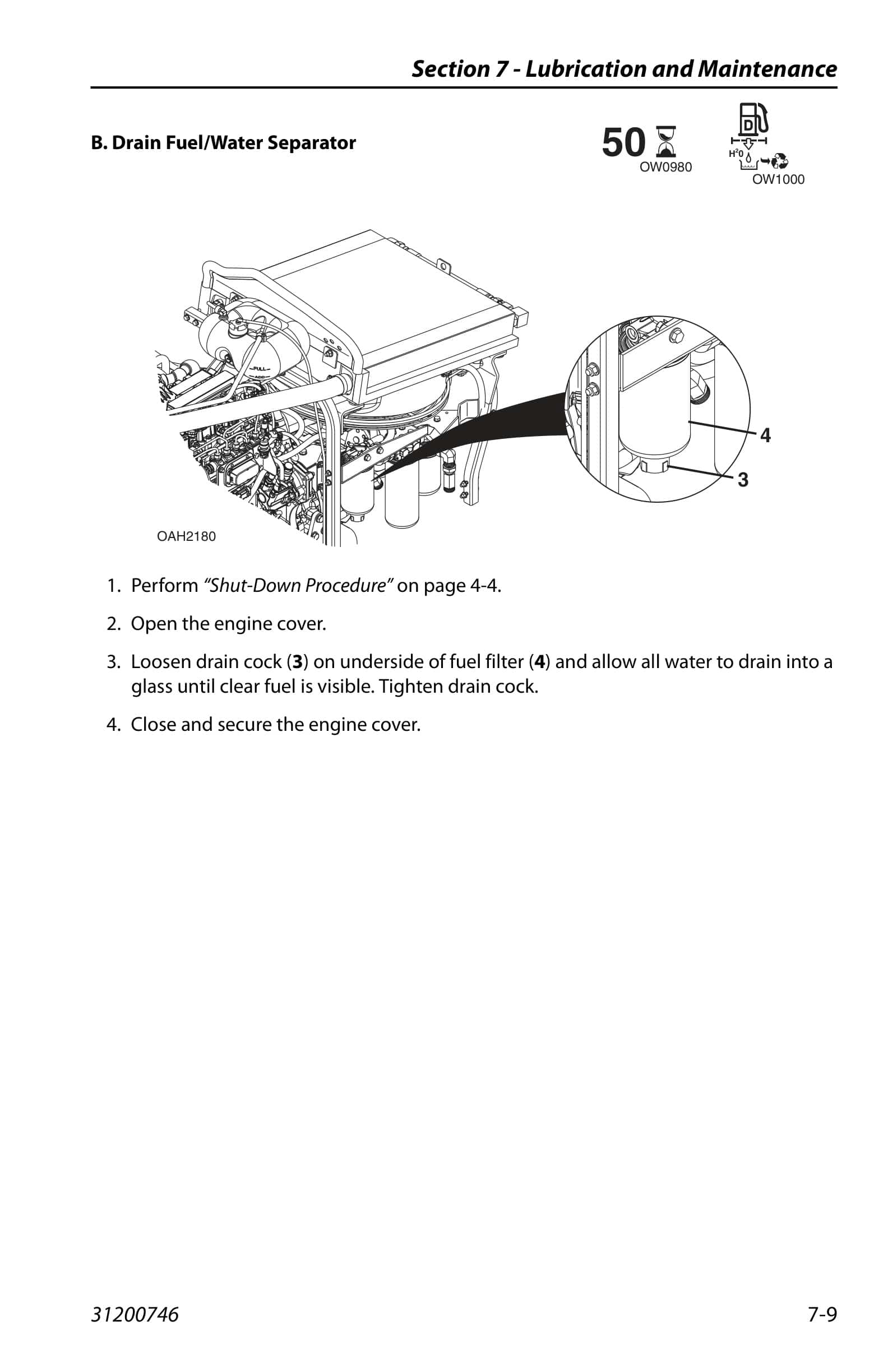
Caterpillar TH255C Operation And Maintenance Manual 31200746
$30.00
- Type Of Manual: Operation And Maintenance Manual
- Manual ID: 31200746
- Number of Pages: 166
- Size: 11.7MB
- Format: PDF
Product details
-
Model List:
- TH255C
- 1. _D _TH255C_CAT_Operation_English
- 1.1. Revision Log
- 1.2. Read This First
- 1.3. Table of Contents
- 1.3.1. Section 1 – General Safety Practices
- 1.3.2. Section 2 – Pre-Operation and Inspection
- 1.3.3. Section 3 – Controls and Indicators
- 1.3.4. Section 4 – Operation
- 1.3.5. Section 5 – Attachments and Hitches
- 1.3.6. Section 6 – Emergency Procedures
- 1.3.7. Section 7 – Lubrication and Maintenance
- 1.3.8. Section 8 – Additional Checks
- 1.3.9. Section 9 – Specifications
- 1.4. Section 1 – General Safety Practices
- 1.4.1. Hazard Classification System
- 1.4.1.1. Safety Alert System and Safety Signal Words
- 1.4.2. General Precautions
- 1.4.3. Operation Safety
- 1.4.3.1. Electrical Hazards
- 1.4.3.2. Tip Over Hazard
- 1.4.3.3. Travel Hazard
- 1.4.3.4. Load Falling Hazard
- 1.4.3.5. Lifting Personnel
- 1.4.3.6. Driving Hazards on Slopes
- 1.4.3.7. Pinch Points and Crush Hazards
- 1.4.3.8. Fall Hazard
- 1.4.3.9. Chemical Hazards
- 1.4.4. Product Link (if equipped)
- 1.4.4.1. Federal Communications Commission (FCC) Information for Users
- 1.5. Section 2 – Pre-Operation and Inspection
- 1.5.1. Preparation, Inspection and Maintenance
- 1.5.2. Pre-Operation Check and Inspection
- 1.5.3. Safety Decals
- 1.5.3.1. ANSI (if equipped)
- 1.5.3.2. ISO (CE AUS) (ANSI, if equipped)
- 1.5.4. Walk-Around Inspection
- 1.5.5. Warm-Up and Operational Checks
- 1.5.5.1. Warm-Up Check
- 1.5.5.2. Operational Check
- 1.5.6. Operator Cab
- 1.5.7. Windows
- 1.5.7.1. Cab Door Window (if equipped)
- 1.5.7.2. Rear Window
- 1.6. Section 3 – Controls and Indicators
- 1.6.1. General
- 1.6.2. Controls
- 1.6.2.1. Park Brake
- 1.6.2.2. Parking Procedure
- 1.6.2.3. Ignition
- 1.6.2.4. Transmission Control Lever
- 1.6.2.5. Load Stability Indicator – LSI (CE AUS)
- 1.6.2.6. LSI Override Switch (CE AUS)
- 1.6.2.7. Steering Column Adjuster (if equipped)
- 1.6.2.8. Instrument Panel
- 1.6.2.9. Joystick
- 1.6.2.10. Right Hand Console
- 1.6.2.11. Accessory Control Lever (if equipped)
- 1.6.2.12. Reversing Fan (if equipped)
- 1.6.3. Steer Modes
- 1.6.3.1. Steer Mode Change
- 1.6.4. Operator Seat
- 1.6.4.1. Operator Presence (CE AUS)
- 1.6.4.2. Adjustments
- 1.6.4.3. Seat Belt
- 1.6.5. Boom Angle and Extension Indicators
- 1.6.6. Reverse Sensing System
- 1.7. Section 4 – Operation
- 1.7.1. Engine
- 1.7.1.1. Starting the Engine
- 1.7.1.2. Cold Weather Starting
- 1.7.1.3. Battery Boosted Starting
- 1.7.1.4. Normal Engine Operation
- 1.7.1.5. Shut-Down Procedure
- 1.7.2. Operating with a Non-Suspended Load
- 1.7.2.1. Lift Load Safely
- 1.7.2.2. Before Picking Up a Load
- 1.7.2.3. Transporting a Load
- 1.7.2.4. Leveling Procedure
- 1.7.2.5. Placing a Load
- 1.7.2.6. Disengaging a Load
- 1.7.3. Operating with a Suspended Load (ANSI CE)
- 1.7.3.1. Lift Load Safely
- 1.7.3.2. Picking Up a Suspended Load
- 1.7.3.3. Transporting a Suspended Load
- 1.7.3.4. Leveling Procedure
- 1.7.3.5. Placing a Suspended Load
- 1.7.3.6. Disengaging a Suspended Load
- 1.7.4. Road Operation (CE)
- 1.7.5. Loading and Securing for Transport
- 1.7.5.1. Tiedown
- 1.7.5.2. Lifting
- 1.8. Section 5 – Attachments and Hitches
- 1.8.1. Approved Attachments
- 1.8.2. Unapproved Attachments
- 1.8.3. JLG Supplied Attachments
- 1.8.4. Telehandler/Attachment/Fork Capacity
- 1.8.5. Use of the Load Chart
- 1.8.5.1. Capacity Indicator Locations
- 1.8.5.2. Sample Load Chart (ANSI CE)
- 1.8.5.3. Sample Load Chart (AUS)
- 1.8.5.4. Example
- 1.8.6. Attachment Installation
- 1.8.6.1. Standard Quick Coupler
- 1.8.6.2. Universal Quick Coupler (UQC)
- 1.8.7. Hydraulic Operated Attachment
- 1.8.8. Adjusting/Moving Forks
- 1.8.9. Attachment Operation
- 1.8.9.1. Carriage with Forks
- 1.8.9.2. Fork Mounted Hook (ANSI CE)
- 1.8.9.3. Rotate/Side Tilt Carriage
- 1.8.9.4. Side Shift Carriage
- 1.8.9.5. Multipurpose Bucket
- 1.8.9.6. Grapple Bucket and Muck Fork Grapple
- 1.8.9.7. Material Handling Arm (ANSI CE)
- 1.8.9.8. Coupler Mounted Hook
- 1.8.10. Hitches
- 1.8.10.1. Retrieval Hitch
- 1.8.10.2. Adjustable Auto Hitch
- 1.8.10.3. Pin Hitch – CUNA C
- 1.8.10.4. EEC Manual Pin Hitch
- 1.9. Section 6 – Emergency Procedures
- 1.9.1. Towing a Disabled Product
- 1.9.1.1. Moving Short Distances
- 1.9.1.2. Moving Longer Distances
- 1.9.2. Emergency Lowering of Boom
- 1.9.3. Emergency Exit from Enclosed Cab
- 1.9.3.1. Inside Cab
- 1.9.3.2. Outside Cab (if equipped)
- 1.10. Section 7 – Lubrication and Maintenance
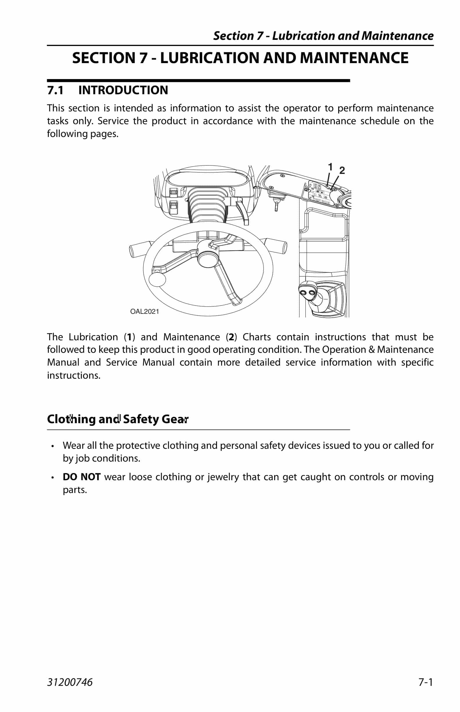
- 1.10.1. Introduction
- 1.10.1.1. Clothing and Safety Gear
- 1.10.2. General Maintenance Instructions
- 1.10.3. Service and Maintenance Schedule
- 1.10.3.1. 1st 50 50 Hour Maintenance Schedule
- 1.10.3.2. t 250, 250 500 Hour Maintenance Schedule
- 1.10.3.3. 1500 Hour Maintenance Schedule
- 1.10.4. Lubrication Schedules
- 1.10.4.1. Hour Lubrication Schedule
- 1.10.5. Operator Maintenance Instructions
- 1.10.5.1. Fuel System
- 1.10.5.2. Engine Oil
- 1.10.5.3. Hydraulic Oil
- 1.10.5.4. Air Intake System
- 1.10.5.5. Engine Cooling System
- 1.10.5.6. Battery
- 1.10.5.7. Brake System
- 1.10.5.8. Windshield Washer System (if equipped)
- 1.11. Section 8 – Additional Checks
- 1.11.1. General
- 1.11.2. Load Stability Indicator System (CE AUS)
- 1.11.3. Reverse Sensing System (if equipped)
- 1.12. Section 9 – Specifications
- 1.12.1. Product Specifications
- 1.12.1.1. Capacities
- 1.12.1.2. Performance
- 1.12.1.3. Dimensions
- 1.12.1.4. Declaration of Vibration (CE)
- 1.12.1.5. Noise Emission Level (CE)
- 1.12.1.6. Machine Towing Capacity
Related products
-
Caterpillar BUC-SCR 120 Series Battery Charger Operation And Maintenance Manual BI001952
$30.00 Add to cart -
Caterpillar Cervis Control System Operation Manual BI001580
$30.00 Add to cart -
Caterpillar CM345-N Continuous Miner Operation And Maintenance Manual BI001588
$30.00 Add to cart -
Caterpillar CM345 Continuous Miner Operation And Maintenance Manual BI001593-02
$30.00 Add to cart -
Caterpillar CM235 Continuous Miner Operation And Maintenance Manual A6474X454
$30.00 Add to cart


