

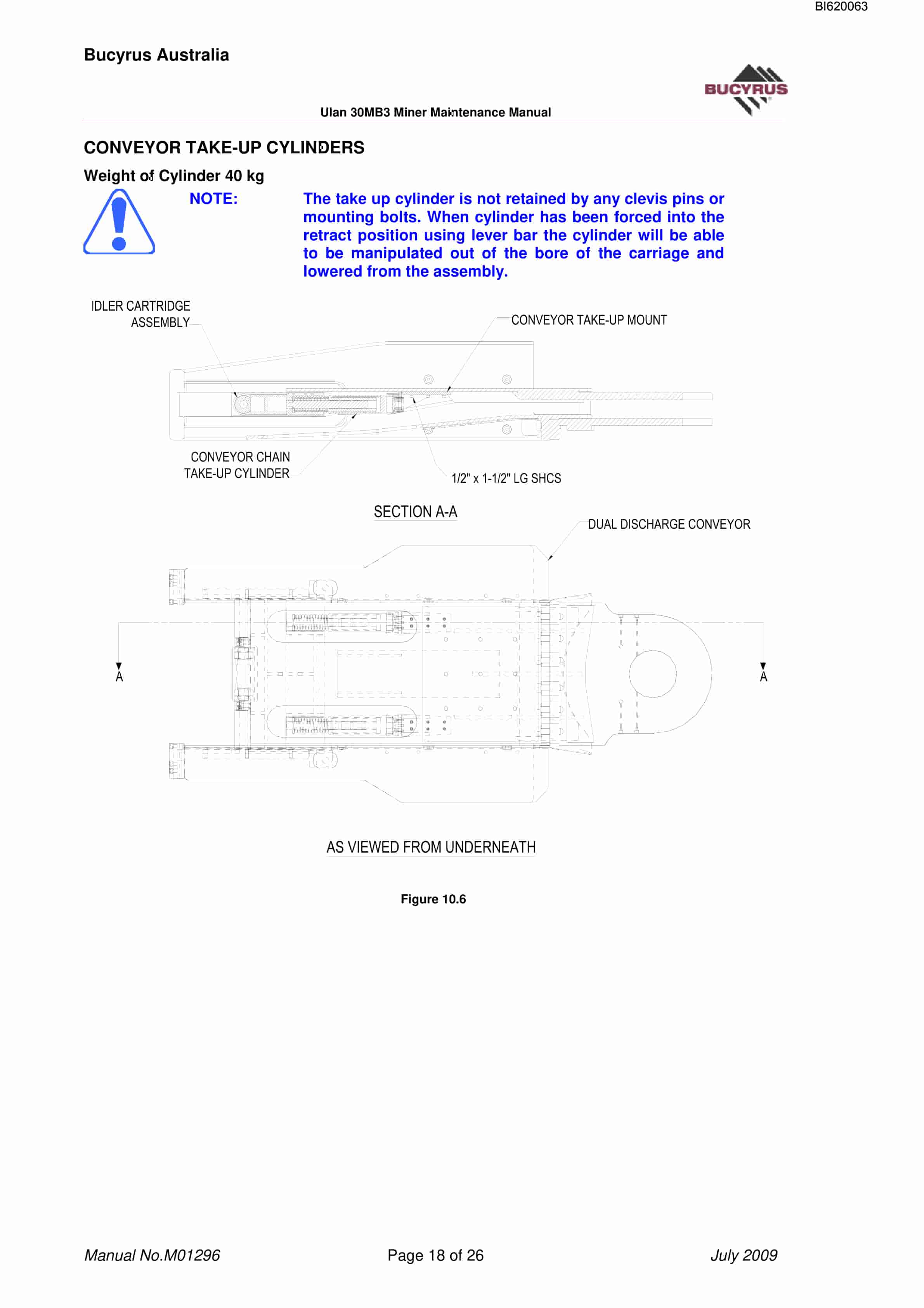
Bucyrus 30MB3 Technical Manual BI620063
$30.00
- Type Of Manual: Technical Manual
- Manual ID: BI620063
- Number of Pages: 257
- Size: 11.6MB
- Format: PDF
Product details
-
Model List:
- 30MB3
- 1. M01296.pdf
- 1.1. Maintenance Manual Contents
- 1.1.1. Section 1 Machine Description
- 1.1.2. Section 9 Mainframe
- 1.2. Section 01 Machine Description.
- 1.3. Section 2 Operating instructions
- 1.4. Section 3 Defects, Hazards and Safety
- 1.5. Section 4 General Maintenance
- 1.5.1. General Maintenance
- 1.5.1.1. MAINTENANCE AND THE CONTINUOUS MINER
- 1.5.1.2. TORQUES
- 1.5.1.3. DUO-CONE SEALS
- 1.5.1.4. MAINTENANCE GUIDELINES
- 1.5.1.5. BEARING AND GEARS
- 1.5.1.5.1. Bearing General
- 1.5.1.5.2. Bearing Assembly Methods
- 1.5.1.5.3. Assembly Methods
- 1.5.1.5.4. Heating Bearings
- 1.5.1.5.5. Freezing/Shrinking Bearing Cups
- 1.5.1.5.6. Tapered Roller Bearing Adjustment
- 1.5.1.5.7. Bevel Gear Adjustment
- 1.5.1.5.8. Bearings General
- 1.5.1.5.9. Bearing Assembly Methods
- 1.5.1.5.10. Assembly Methods
- 1.5.1.5.11. Heating Bearings
- 1.5.1.5.12. Freezing/Shrinking Bearing Cups
- 1.5.1.5.13. Tapered rolling Bearing Adjustment
- 1.5.1.5.14. Bevel Gear Adjustment
- 1.5.1.6. LOCKWIRING FASTENERS
- 1.5.1.6.1. Single Wire
- 1.5.1.6.2. Wired in Pairs
- 1.5.1.7. SPECIAL FASTENERS
- 1.5.1.8. SELF-LOCKING SCREWS
- 1.5.1.8.1. Installation Recommendations
- 1.5.1.9. LOCKNUTS
- 1.5.1.9.1. Installation Recommendations
- 1.5.1.10. COMPONENT SUBSTITUTION
- 1.5.1.11. SAFETY IN MAINTENANCE
- 1.6. Section 5 Cutting Head Assy
- 1.6.1. GENERAL DESCRIPTION
- 1.6.2. REMOVAL OF PULL IN ASSEMBLY COMPLETE
- 1.6.3. REMOVAL OF CUTTING DRUMS
- 1.6.3.1. Pull in Drum Assembly
- 1.6.3.2. Drive Drum Removal
- 1.6.3.3. Drive Drum Assembly
- 1.6.4. Intermediate Drum Removal
- 1.6.4.1. Intermediate Drum Removal LH
- 1.6.4.2. Intermediate Drum Assembly Right Hand and Left Hand
- 1.6.4.3. Install complete in pull Assembly
- 1.6.4.4. Centre Drum Removal
- 1.6.4.5. Centre Drum Assembly
- 1.6.4.6. Clutch Assembly
- 1.6.4.7. Removal of the Cutting Head Gear Case Complete With Pull in Assemblies
- 1.6.4.8. Reinstall Cutter Head Gear case Complete with Pull in Assemblies
- 1.6.4.9. Removal of Cutter Head Motor (LH and RH)
- 1.6.4.10. Installation of Cutter head Motor
- 1.6.4.11. Removal of the Cutting Head Input Gearcase
- 1.6.4.12. Installation of Cutter Head Input Gear case
- 1.6.5. REMOVAL OF THE CUTTING HEAD SUPPORT FROM THE MAINFRAME
- 1.6.6. INSTALLATION OF CUTTING HEAD ASSEMBLY TO THE MAIN FRAME
- 1.7. Section 6 Gathering Head Assy
- 1.7.1. GENERAL DESCRIPTION
- 1.7.2. REMOVAL AND REPLACING GATHERING HEAD SHEAR SHAFT
- 1.7.3. CONVEYOR CHAIN DISASSEMBLY
- 1.7.4. REMOVAL OF FOOT SHAFT AND CLAs
- 1.7.4.1. Removing the CLAs
- 1.7.4.2. Refitting the CLAs
- 1.7.5. REMOVAL OF DRIVE MOTOR INPUT GEAR CASE AND C.L.A POT
- 1.7.6. REASSEMBLY OF GATHERING HEAD GEARCASES
- 1.7.7. REMOVAL OF THE GATHERING HEAD FROM THE MAIN FRAME
- 1.7.8. INSTALLATION OF THE GATHERING HEAD
- 1.8. Section 7 Conveyor Assy
- 1.8.1. GENERAL DESCRIPTION
- 1.8.2. CONVEYOR CHAIN REMOVAL
- 1.8.3. CONVEYOR CHAIN INSTALLATION
- 1.8.4. REMOVAL OF THE CONVEYOR ASSEMBLY FROM THE MINER
- 1.8.5. INSTALLATION OF THE CONVEYOR ASSEMBLY
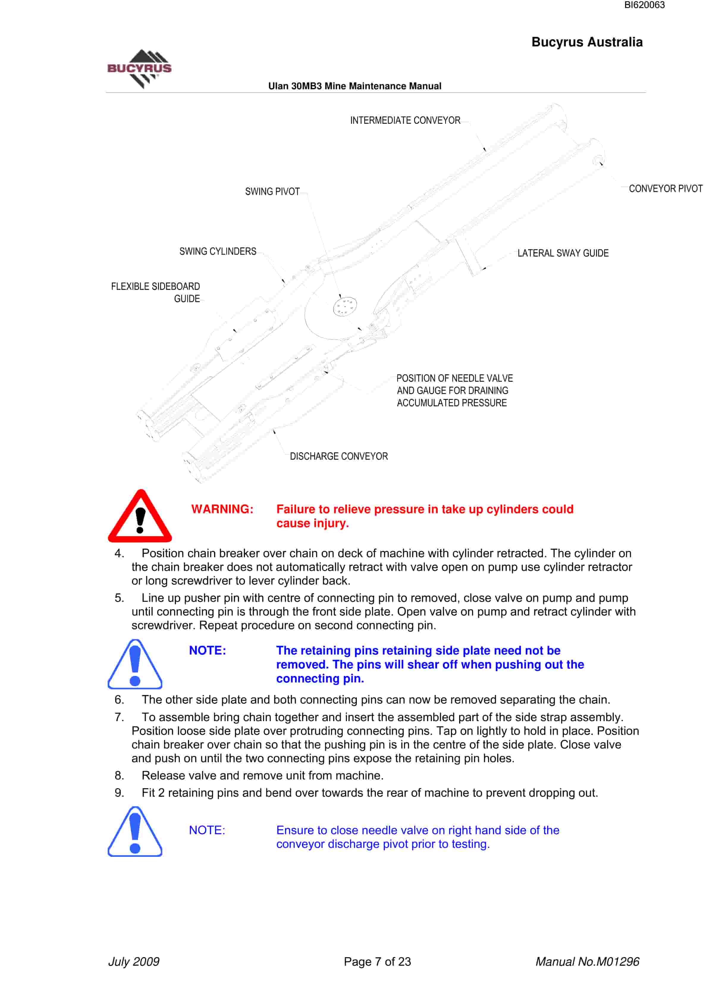
- 1.8.6. REMOVAL OF DISCHARGE CONVEYOR
- 1.8.7. REMOVAL OF TAIL ROLLER
- 1.9. Section 8 Traction System
- 1.9.1. GENERAL DESCRIPTION
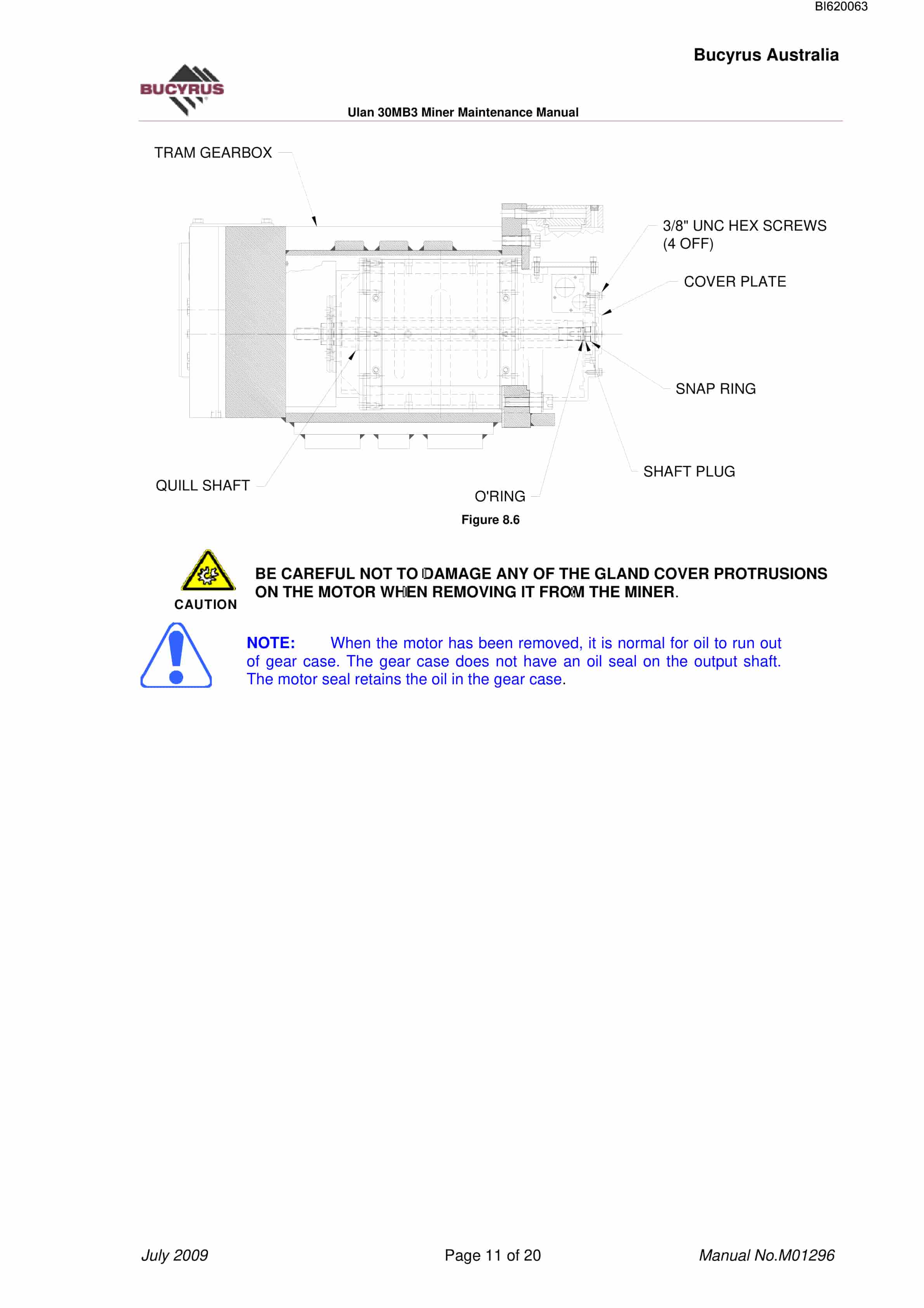
- 1.9.2. REMOVAL OF THE TRAM DRIVE GEAR CASE ASSEMBLYCOMPLETE WITH DRIVE MOTOR
- 1.9.3. INSTALLATION OF THE TRAM DRIVE GEAR CASE ASSEMBLY
- 1.9.4. INSTALLATION OF A TRAM MOTOR
- 1.9.5. CRAWLER CHAIN REMOVAL
- 1.9.6. CRAWLER CHAIN INSTALLATION
- 1.9.7. CRAWLER TAKE-UP ROLLER REMOVAL
- 1.9.8. CRAWLER TAKE-UP ROLLER INSTALLATION
- 1.10. Section 9 Mainframe
- 1.10.1. STABLISING SHOE ASSEMBLY
- 1.10.1.1. Stabiliser Cylinder Removal
- 1.10.1.2. Cylinder Installation
- 1.10.2. STABILISER SHOE REMOVAL
- 1.10.3. SHOE INSTALLATION
- 1.11. Section 10 Cylinder Servicing
- 1.11.1. CYLINDER REMOVAL AND INSTALLATION
- 1.11.2. CUTTERHEAD RAISE AND LOWER CYLINDER
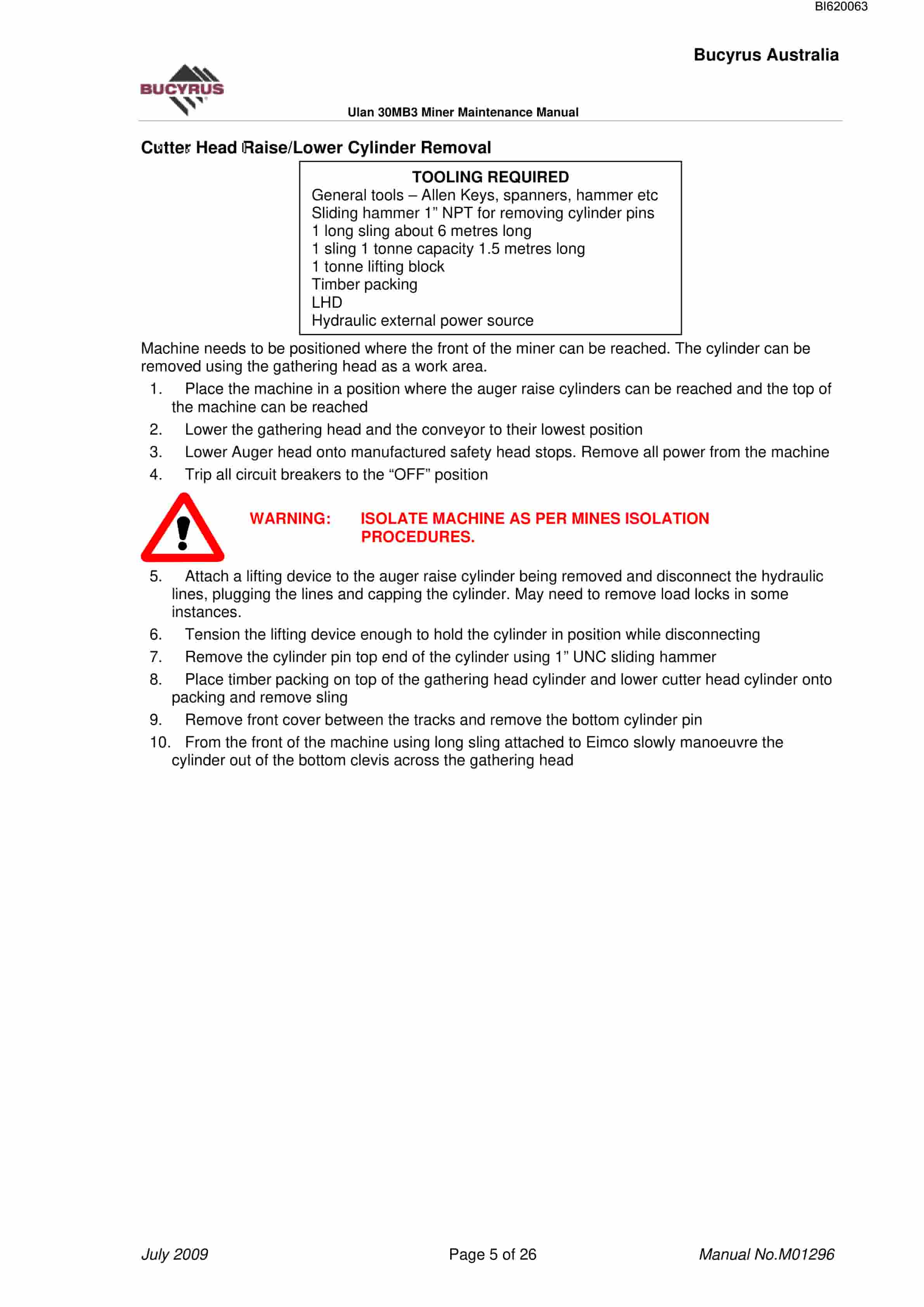
- 1.11.2.1. Cutter Head Raise/Lower Cylinder Removal
- 1.11.2.2. Cutter Head Raise/Lower Cylinder Installation
- 1.11.3. GATHERING HEAD RAISE AND LOWER CYLINDER
- 1.11.3.1. Gathering Head Raise/Lower Cylinder Removal
- 1.11.3.2. Gathering Head Raise/Lower Cylinder Installation
- 1.11.4. CONVEYOR RAISE AND LOWER CYLINDER
- 1.11.4.1. Conveyor Raise/Lower Cylinder Removal
- 1.11.4.2. Conveyor Raise/Lower Cylinder Installation
- 1.11.5. CONVEYOR SWING CYLINDER
- 1.11.5.1. Conveyor Swing Cylinder Removal
- 1.11.5.2. Conveyor Swing Cylinder Installation
- 1.11.6. PLOW CYLINDERS
- 1.11.6.1. Plow Cylinder Removal
- 1.11.6.2. Plow Cylinder Installation
- 1.11.7. CONVEYOR TAKE-UP CYLINDERS
- 1.11.7.1. Conveyor Take-up Cylinder Removal
- 1.11.7.2. Conveyor Take-up Cylinder Installation
- 1.11.8. HYDRAULIC PUMP INSTALLATION
- 1.11.9. REMOVAL AND REPLACEMENT OF PUMP DRIVE MOTOR
- 1.11.9.1. Pump Drive Motor Removal
- 1.11.9.2. Pump Drive Motor Installation
- 1.12. Section 11 Operator Servicing And Maintenance
- 1.12.1. OPERATOR / TRADESMAN SERVICING AND MAINTENANCE
- 1.12.2. TOP VIEW LUBRICATION
- 1.12.3. LEFT HAND SIDE LUBRICATION
- 1.12.4. LUBRICATION CHART
- 1.12.5. LUBRICATION GEAR OIL
- 1.12.5.1. Tram Gear cases
- 1.12.5.2. Cutter Head Gear Cases
- 1.12.5.3. Cutter Head Input Gear Cases
- 1.12.5.4. Gathering Head (POT) Gear Cases
- 1.12.5.5. Gathering Head Input Gear Cases
- 1.12.5.6. Traction Idler Roller
- 1.12.6. GREASING
- 1.12.7. TRAM BRAKES
- 1.12.8. FILTERS
- 1.12.8.1. Right Hand Filters
- 1.12.9. CHAIN ADJUSTMENTS
- 1.12.9.1. Crawler Track Chain Adjustment
- 1.12.10. MAINTENANCE MODE
- 1.12.10.1. Check and Fill Hydraulic Oil Reservoir
- 1.12.10.2. Hydraulic Oil Power Fill
- 1.12.10.3. Gear Case Oil Power Fill
- 1.12.11. REPAIR OR REPLACE WATERSPRAYS
- 1.12.12. MACHINE CUTTING PICKS
- 1.13. Section 12 Hydraulic components assembly
- 1.13.1. DESCRIPTION
- 1.13.2. MECHANICAL
- 1.13.3. HYDRAULICS
- 1.13.4. HYDRAULIC PUMP
- 1.13.4.1. Power Cut Off Control D
- 1.13.4.2. Load Sensing Control S
- 1.13.5. PUMP ADJUSTMENT
- 1.13.5.1. Power Controller LR
- 1.13.6. VALVE BANK INFORMATION
- 1.13.7. ADJUSTMENTS
- 1.13.7.1. Conveyor Tension and Tramming Brake Coolant
- 1.14. Section 13 Water General
- 1.14.1. Water Reticulation
- 1.14.1.1. GENERAL
- 1.14.1.1.1. Circuit 1 (Right Side)
- 1.14.1.1.2. Circuit 2 (Left Side)
- 1.14.1.1.3. Tramming
- 1.14.1.1.4. Water Sprays
- 1.15. Section 14 Maintenance Matrix
Related products
-
Bucyrus General Data Technical Handbook 2804198
$30.00 Add to cart -
Bucyrus Continuous Miner Spare Parts List 907782
$30.00 Add to cart -
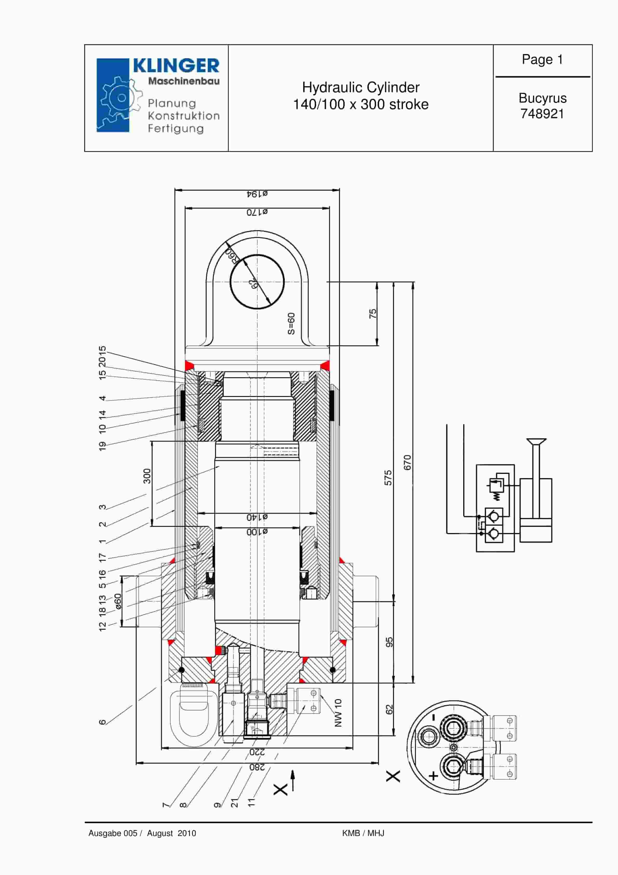
Bucyrus Hydraulic Cylinder 140-100 x 300 Stroke Service Parts List 748921
$30.00 Add to cart -
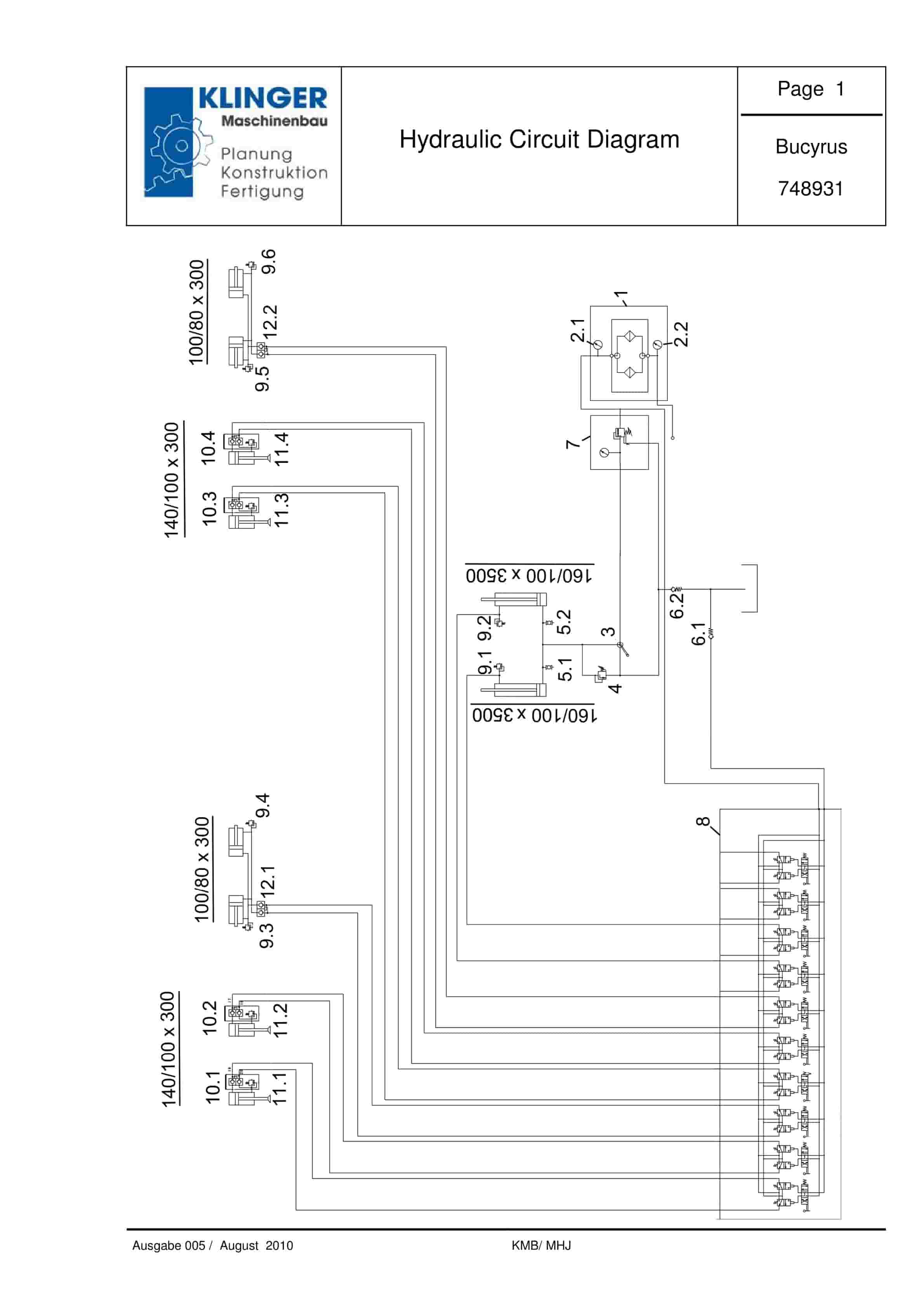
Bucyrus Hydraulic Circuit Diagram Service Parts List 748931
$30.00 Add to cart -
Bucyrus Gleithobel Plow Outrigger Steering System Technical Description 1999 001 031 BA 00
$30.00 Add to cart


