

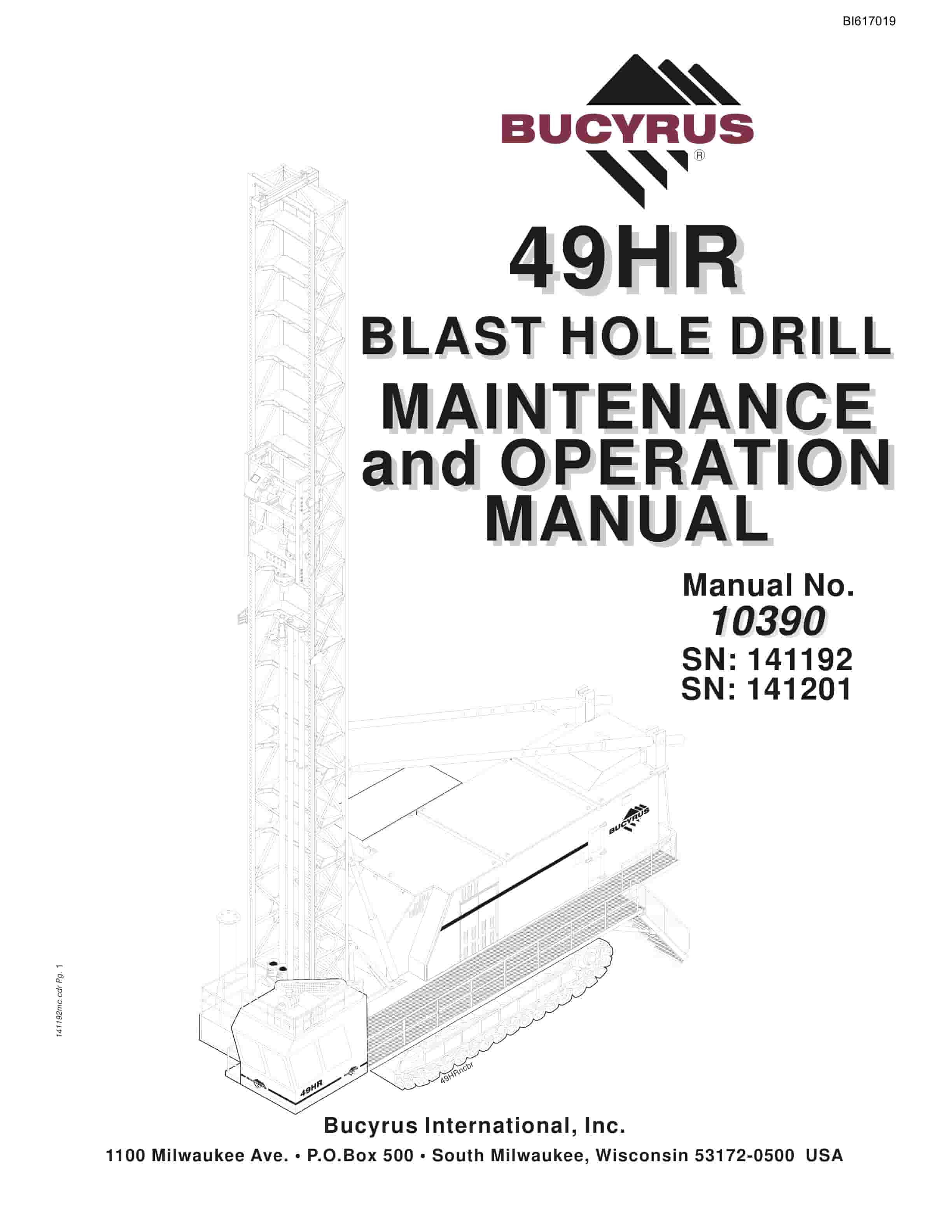
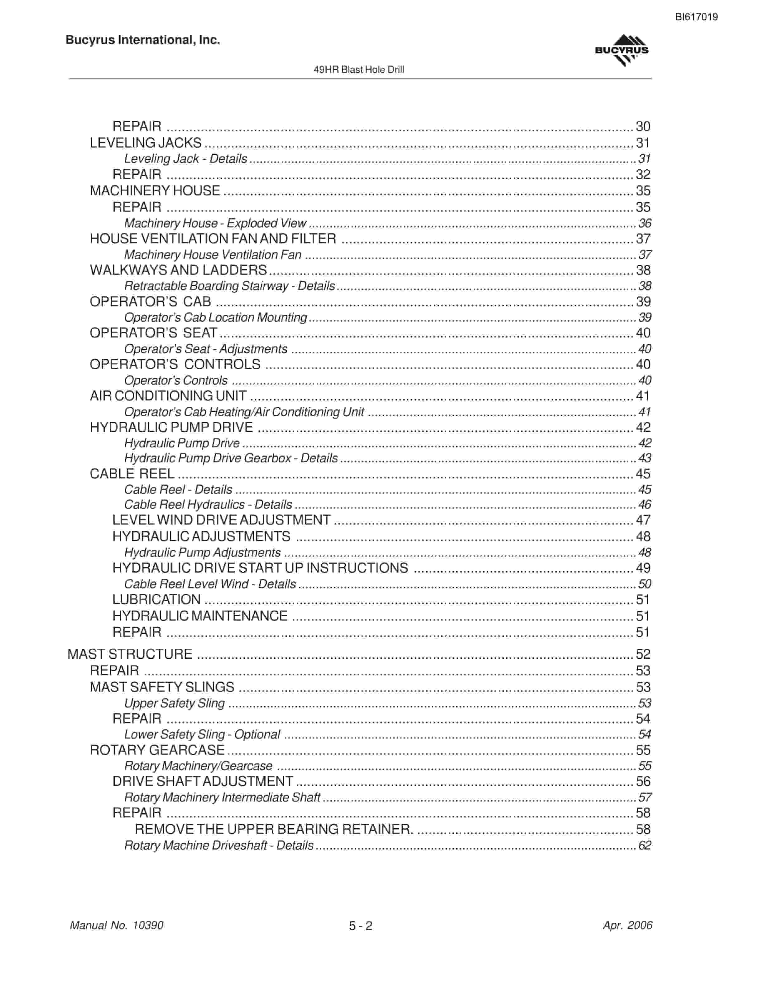
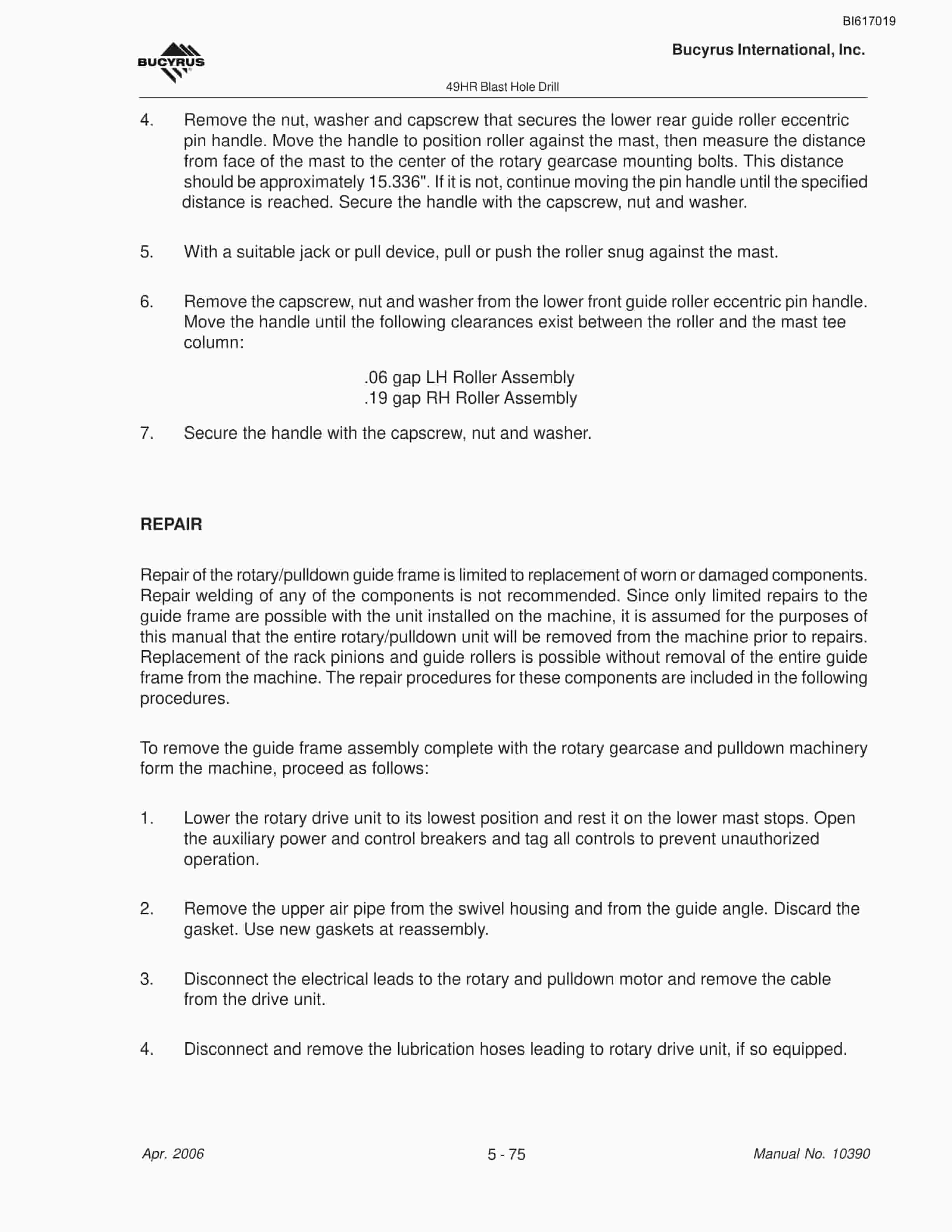
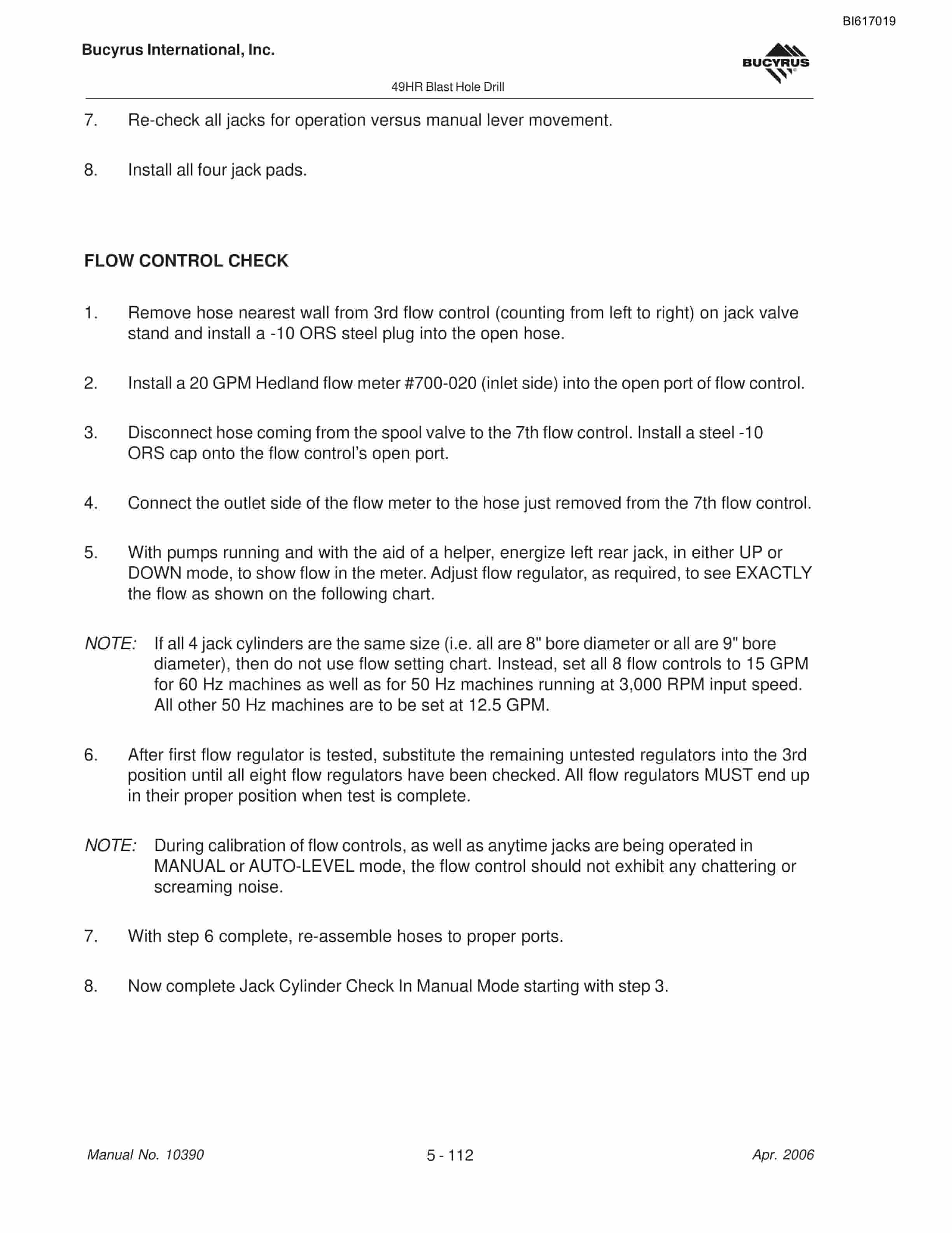
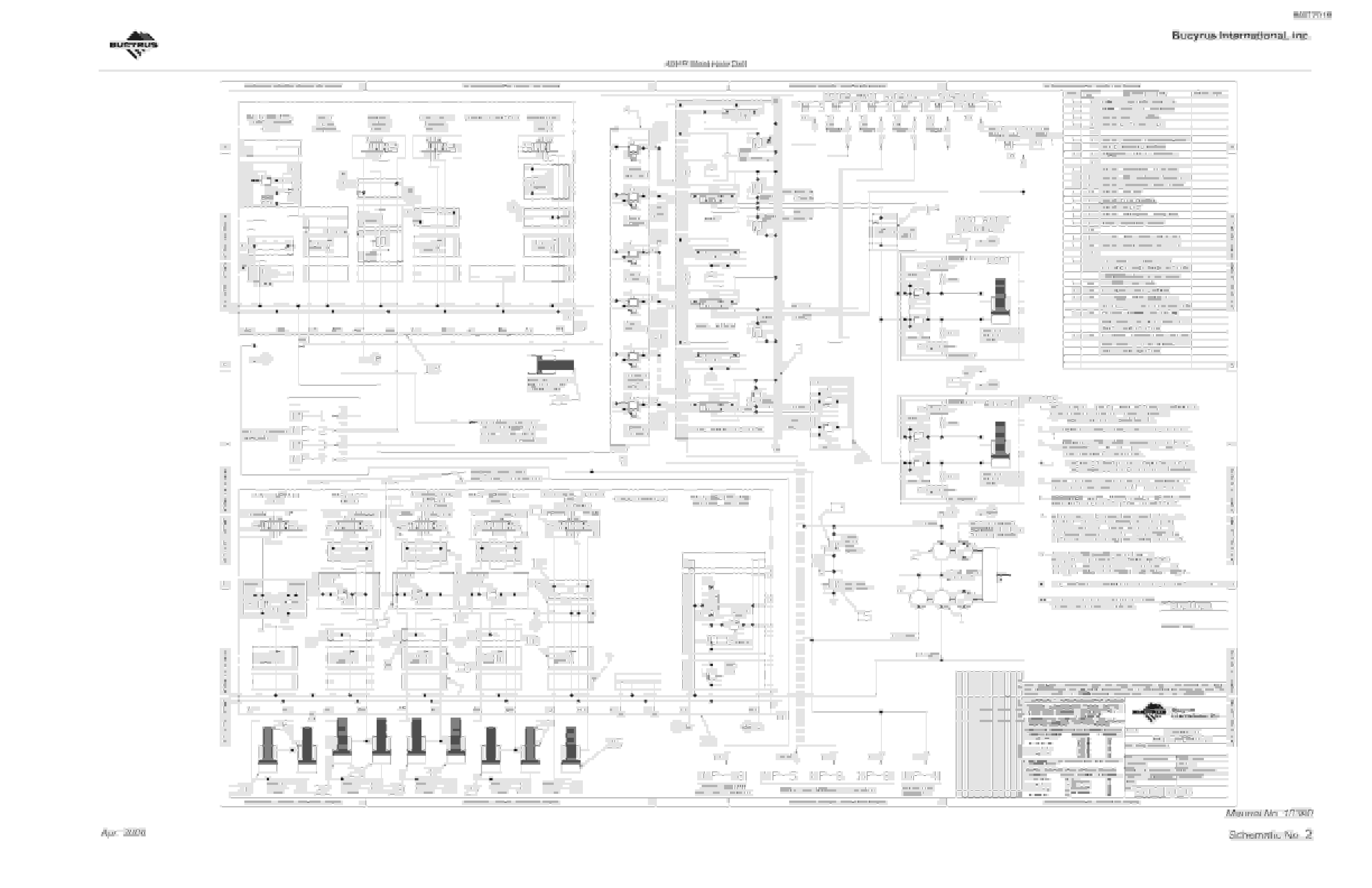
Bucyrus 49HR Blast Hole Drill Maintenance And Operation Manual BI617019
$30.00
- Type Of Manual: Maintenance And Operation Manual
- Manual ID: BI617019
- Number of Pages: 440
- Size: 9.3MB
- Format: PDF
Product details
-
Model List:
- 49HR Blast Hole Drill
- 1. _1.pdf
- 1.1. _1.pdf
- 1.1.1. Table of Contents
- 2. _2.pdf
- 2.1. Table of Contents
- 2.1.1. GENERAL INFORMATION
- 2.1.2. OPERATION NEAR ELECTRICAL TRANSMISSION LINES
- 2.1.3. CONTROLS – LOCATION AND FUNCTION
- 2.1.4. OPERATORS CONTROL console
- 2.1.5. OPERATORS CONTROL CONSOLE – OVERVIEW
- 2.1.6. Main Control Panel
- 2.1.7. MAIN CONTROL PANEL – OVERVIEW
- 2.1.8. Hoist/Pulldown Rheostat
- 2.1.9. Rotary Rheostat
- 2.1.10. Drill/Propel Controls ON and OFF Push-button
- 2.1.11. Hoist/Pulldown Speed Selector Switch
- 2.1.12. Rotary Speed Selector Switch
- 2.1.13. Hoist Brake Switch
- 2.1.14. Pipe Rack Selector Switch
- 2.1.15. Pipe Rack Joystick (Left Crawler Propel)
- 2.1.16. Winch/Mast Selector Switch
- 2.1.17. Mast/Winch Joystick (Right Crawler Propel)
- 2.1.18. Tool Wrench Switch
- 2.1.19. Dust Curtain Switch
- 2.1.20. Bit View Hatch Switch
- 2.1.21. Propel Control Panel
- 2.1.22. PROPEL CONTROL PANEL – OVERVIEW
- 2.1.23. Emergency Stop Push-button (Optional)
- 2.1.24. Propel Speed Selector Switch
- 2.1.25. Compressor Stop Push-button
- 2.1.26. Compressor Vent/Drill Switch
- 2.1.27. Heater/Vent/Air Conditioner Controls
- 2.1.28. Operating Mode Selector Switch
- 2.1.29. Propel Joysticks
- 2.1.30. Selector Switch Panel
- 2.1.31. SELECTOR SWITCH PANEL – OVERVIEW
- 2.1.32. Breakout Wrench Switch
- 2.1.33. Pipe Positioner Switch (Optional)
- 2.1.34. Dust Seal Switch (Optional)
- 2.1.35. A-Frame Lock Switch (Optional)
- 2.1.36. Mast Brace Lock Switch
- 2.1.37. Mast Lock Switch
- 2.1.38. Boarding Stairs Switch
- 2.1.39. Pedestal Heater Switch (Optional)
- 2.1.40. Fire Suppression System Indicators (Optional)
- 2.1.41. RADIO (Optional)
- 2.1.42. Leveling Control Panel
- 2.1.43. LEVELING CONTROL PANEL
- 2.1.44. Manual Leveling Joysticks
- 2.1.45. Automatic Leveling Switch
- 2.1.46. Water Injection On/Off Switch (Optional)
- 2.1.47. Water Injection Flow Control (Optional)
- 2.1.48. Horn Push-button
- 2.1.49. Depth Indicator Reset Push-button
- 2.1.50. Programmed Drill Control Switch
- 2.1.51. Emergency Stop Push-button (optional)
- 2.1.52. Operators Display Terminal
- 2.1.53. OPERATORS DISPLAY PANEL
- 2.1.54. Machinery House Controls
- 2.1.55. Lighting Load Center
- 2.1.56. LIGHTING LOAD CENTER
- 2.1.57. Controls Located On Low Voltage Start Cabinet
- 2.1.58. TYPICAL LOW VOLTAGE START CABINET
- 2.1.59. Controls Located On Low Voltage Cabinet
- 2.1.60. TYPICAL LOW VOLTAGE CABINET
- 2.1.61. Control Located On Programmable Controller Cabinet
- 2.1.62. TYPICAL PROGRAMMABLE CONTROL CABINET
- 2.1.63. Hoist/Pulldown and Rotary Drive Control CABINETS
- 2.1.64. TYPICAL HOIST/PULLDOWN AND ROTARY DRIVE CONTROL CABINETS
- 2.1.65. Miscellaneous Controls
- 2.1.66. Portable Remote Propel Station (Optional)
- 2.1.67. PORTABLE REMOTE PROPEL STATION
- 2.1.68. Hydraulic Reservoir Remote Fill Control Panel
- 2.1.69. HYDRAULIC RESERVOIR REMOTE FILL CONTROL PANEL
- 2.1.70. Lube Control Panel
- 2.1.71. LUBE CONTROL PANEL
- 2.1.72. Prestart Checks
- 2.1.73. EXTERNAL Inspection
- 2.1.74. Onboard Inspection
- 2.1.75. Prestart Lubrication
- 2.1.76. START-UP
- 2.1.77. Machine Start Up
- 2.1.78. Machinery Check
- 2.1.79. Break-In of New Components
- 2.1.80. Rotary Drive unit Break-In
- 2.1.81. Hoist/Pulldown Gearcase Break-In
- 2.1.82. Electric Motor Break-In
- 2.1.83. OPERATION
- 2.1.84. Propelling
- 2.1.85. Definitions
- 2.1.86. PROPEL Procedure
- 2.1.87. PROPEL CONTROLS – OVERVIEW
- 2.1.88. STRAIGHT PROPEL
- 2.1.89. GRADUAL RIGHT HAND TURN
- 2.1.90. GRADUAL LEFT HAND TURN
- 2.1.91. COUNTER-ROTATION LEFT HAND TURN
- 2.1.92. ENSURE GRADUAL TURNS ARE MADE – 15O INCREMENTS
- 2.1.93. Towing PROCEDURE
- 2.1.94. TOWING PROCEDURE
- 2.1.95. Cable Reel Operation
- 2.1.96. CABLE REEL
- 2.1.97. Leveling
- 2.1.98. LEVELING CONTROLS
- 2.1.99. Mast Raising and Lowering
- 2.1.100. Mast Raising
- 2.1.101. MAST RAISING/LOWERING CONTROLS
- 2.1.102. Mast Lowering
- 2.1.103. MAST CONTROLS TO ADJUST FOR ANGLE DRILLING
- 2.1.104. Pulldown Machinery Operation
- 2.1.105. HOIST/PULLDOWN CONTROLS
- 2.1.106. Auxiliary Winch Operation
- 2.1.107. WINCH OPERATION CONTROLS
- 2.1.108. Pipe Rack Operation
- 2.1.109. PIPE RACK OPERATING CONTROLS
- 2.1.110. PIPE RACK OPERATION
- 2.1.111. Tool Handling
- 2.1.112. Pipe Loading and Unloading
- 2.1.113. Drill Tool String Assembly
- 2.1.114. TOOL STRING
- 2.1.115. STABILIZER INSTALLATION
- 2.1.116. DRILL PIPE INSTALLATION CONTROLS
- 2.1.117. Breakout Wrench Operation
- 2.1.118. Drill Tool String Disassembly
- 2.1.119. Adding Additional Drill Pipe
- 2.1.120. Removal of Multiple Section Drill Pipe
- 2.1.121. Angle Drilling
- 2.1.122. ANGLE DRILLING EQUIPMENT
- 2.1.123. PIPE POSITIONER
- 2.1.124. JIB CRANE
- 2.1.125. Dust Suppression System Operation
- 2.1.126. WATER INJECTION SYSTEM
- 2.1.127. DRILLING
- 2.1.128. Vertical Drilling
- 2.1.129. CONTROLS UTILIZED WHILE DRILLING
- 2.1.130. STARTING The Hole (Collaring)
- 2.1.131. Normal Drilling
- 2.1.132. Ending the Hole
- 2.1.133. Ending the Hole (Multiple Pipe Sections)
- 2.1.134. Drilling Difficult Formations
- 2.1.135. Unconsolidated Materials
- 2.1.136. Wet or Sticky Formations
- 2.1.137. Angle Drilling
- 2.1.138. Programmed Drill Control Drilling
- 2.1.139. PROGRAMMED DRILL CONTROLS UTILIZED
- 2.1.140. Preparing to Move
- 2.1.141. MACHINE SHUTDOWN
- 2.1.142. Shut Down Procedure
- 2.1.143. Short Term Storage
- 2.1.144. Long Term Storage
- 2.1.145. Attended Long Term Storage
- 2.1.146. Unattended Long Term Storage
- 2.1.147. TOOL RECOVERY
- 2.1.148. Drill stability charts
- 3. _3.pdf
- 3.1. Table of Contents
- 3.1.1. LUBRICATION PRINCIPLES
- 3.1.2. Auto Lube Control Panel
- 3.1.3. Auto Lube Reservoir
- 3.1.4. Auto Lube Piping Mainframe (View 1)
- 3.1.5. Auto Lube Piping Mainframe (View 2)
- 3.1.6. Auto Lube Piping Crawlers
- 3.1.7. Auto Lube Piping Mast (View 1)
- 3.1.8. Auto Lube Piping Mast (View 2)
- 3.1.9. LINCOLN TYPE SL-1 LUBRICANT INJECTORS
- 3.1.10. Lubricant Injector Operation
- 3.1.11. Injector Advantages
- 3.1.12. Troubleshooting
- 3.1.13. Bit Lubricator
- 3.1.14. FLOWMASTER Pump Servicing
- 3.1.15. Pressure CONTROL VALVE ADJUSTMENT
- 3.1.16. FLOW CONTROL VALVE ADJUSTMENT
- 3.1.17. FlowMaster Rotary Driven Hydraulic Pump Schematic
- 3.1.18. CRANK CASE OIL
- 3.1.19. PUMP DISASSEMBLY PROCEDURE
- 3.1.20. FlowMaster Rotory Driven Hydraulic Pump Assembly
- 3.1.21. PUMP ASSEMBLY PROCEDURE
- 3.1.22. FlowMaster Rotary Driven Hydraulic Pump Components
- 3.1.23. TROUBLESHOOTING
- 3.1.24. MAST LUBRICATION PART 2
- 3.1.25. Lubrication Points
- 3.1.26. GEARCASE AND RESERVOIR CAPACITIES
- 3.1.27. Lower works lubrication
- 3.1.28. MAIN FRAME LUBRICATION
- 3.1.29. MAST LUBRICATION PART 1
- 3.1.30. MAST LUBRICATION PART 3
- 3.1.31. LUBRICANT CLEANLINESS
- 3.1.32. LUBRICATION BENCHMARKS
- 3.1.33. RGL – REGULAR GEAR LUBRICANT
- 3.1.34. General Requirements for RGL Lubricants
- 3.1.35. Dragline Specific Data
- 3.1.36. Dragline Viscosity and Pour Point Requirements
- 3.1.37. Shovel Drill Specific Data
- 3.1.38. Shovel / Drill Viscosity and Pour Point Requirements
- 3.1.39. ASTM Standard Viscosity / Temperature Chart
- 3.1.40. ACSL – AIR COMPRESSOR (SCREW-TYPE) LUBRICANT
- 3.1.41. MPO – Multipurpose OIL
- 3.1.42. RWRL – RUNNING WIRE ROPE LUBRICANT
- 3.1.43. HYDO – Hydraulic Oil
- 3.1.44. PAO Synthetic Hydraulic Fluid
- 3.1.45. Recommended Viscosity vs. OAT Chart
- 3.1.46. Paraffinic Base Petroleum Hydraulic Fluid
- 3.1.47. Recommended Viscosity vs. OAT Chart
- 4. _4.pdf
- 4.1. Table of Contents
- 4.1.1. INTRODUCTION
- 4.1.2. ELEMENTS OF AN EFFECTIVE MAINTENANCE PROGRAM
- 4.1.3. SCHEDULED PREVENTIVE MAINTENANCE PROGRAM
- 4.1.4. General Safety Considerations
- 4.1.5. Maintenance During Machine Operation
- 4.1.6. Maintenance Precautions
- 4.1.7. PREVENTIVE MAINTENANCE FOR Lubrication
- 4.1.8. Lubricant CLEANLINESS
- 4.1.9. Frequency of inspection and maintenance
- 4.1.10. MAINTENANCE SCHEDULES
- 4.1.11. DAILY Check Points
- 4.1.12. external inspection
- 4.1.13. Onboard Inspection
- 4.1.14. AFTER START-UP INSPECTION
- 4.1.15. WEEKLY CHECK points
- 4.1.16. ON-BOARD INSPECTION
- 4.1.17. Monthly Check Points
- 4.1.18. semi-ANNUAL Check Points
- 5. _5.pdf
- 5.1. Table of Contents
- 5.1.1. Crawler Belts
- 5.1.2. Lower Works – Overview
- 5.1.3. Adjustment
- 5.1.4. Crawler Belt Tension – Checking
- 5.1.5. Crawler Belt Adjustment – Details
- 5.1.6. Link Replacement
- 5.1.7. Belt Replacement
- 5.1.8. Crawler Belt Replacement – Details
- 5.1.9. Lower Rollers
- 5.1.10. Lower Roller – Details
- 5.1.11. Repair
- 5.1.12. Upper Rollers
- 5.1.13. Upper Roller – Details
- 5.1.14. Repair
- 5.1.15. Take-up tumblers
- 5.1.16. Repair
- 5.1.17. Drive Tumbler
- 5.1.18. Drive Tumbler and Planetary Gearbox Installation
- 5.1.19. Repair
- 5.1.20. Planetary Gearbox
- 5.1.21. GEARBOX REMOVAL AND INSTALLATION
- 5.1.22. Planetary Gearbox Mount Bolt Torque Sequence
- 5.1.23. Checking/Changing Oil
- 5.1.24. Planetary Gearbox Oil Check – Details
- 5.1.25. LUBRICANT SPECIFICATIONS
- 5.1.26. Planetary Gearbox Lubrication Specifications
- 5.1.27. Oil Change Intervals
- 5.1.28. Crawler frames
- 5.1.29. Repair
- 5.1.30. Crawler Frame Removal/Blocking
- 5.1.31. Equalizer Axle – Details
- 5.1.32. Repair
- 5.1.33. Rear Axle – Details
- 5.1.34. Mainframe
- 5.1.35. Main Frame – Details
- 5.1.36. Repair
- 5.1.37. Bit viewing hatch
- 5.1.38. Bit Viewing Hatch – Details
- 5.1.39. Mast A-Frame
- 5.1.40. Repair
- 5.1.41. Leveling jacks
- 5.1.42. Leveling Jack – Details
- 5.1.43. Repair
- 5.1.44. Machinery House
- 5.1.45. Repair
- 5.1.46. Machinery House – Exploded View
- 5.1.47. House ventilation fan and filter
- 5.1.48. Machinery House Ventilation Fan
- 5.1.49. Walkways and Ladders
- 5.1.50. Retractable Boarding Stairway – Details
- 5.1.51. Operators Cab
- 5.1.52. Operators Cab Location Mounting
- 5.1.53. Operators Seat
- 5.1.54. Operators Seat – Adjustments
- 5.1.55. Operators Controls
- 5.1.56. Operators Controls
- 5.1.57. Air Conditioning Unit
- 5.1.58. Operators Cab Heating/Air Conditioning Unit
- 5.1.59. Hydraulic pump drive
- 5.1.60. Hydraulic Pump Drive
- 5.1.61. Hydraulic Pump Drive Gearbox – Details
- 5.1.62. Cable Reel
- 5.1.63. Cable Reel – Details
- 5.1.64. Cable Reel Hydraulics – Details
- 5.1.65. Level Wind Drive Adjustment
- 5.1.66. Hydraulic Adjustments
- 5.1.67. Hydraulic Pump Adjustments
- 5.1.68. HYDRAULIC DRIVE START UP INSTRUCTIONS
- 5.1.69. Cable Reel Level Wind – Details
- 5.1.70. Lubrication
- 5.1.71. Hydraulic Maintenance
- 5.1.72. Repair
- 5.1.73. Mast Structure
- 5.1.74. Repair
- 5.1.75. Mast Safety Slings
- 5.1.76. Upper Safety Sling
- 5.1.77. Repair
- 5.1.78. Lower Safety Sling – Optional
- 5.1.79. Rotary Gearcase
- 5.1.80. Rotary Machinery/Gearcase
- 5.1.81. Drive Shaft Adjustment
- 5.1.82. Rotary Machinery Intermediate Shaft
- 5.1.83. Repair
- 5.1.84. Remove the upper bearing retainer.
- 5.1.85. Rotary Machine Driveshaft – Details
- 5.1.86. Rotary Motor
- 5.1.87. Rotary Drive Motor – Details
- 5.1.88. Rotary Coupling
- 5.1.89. Repair
- 5.1.90. Rotary Shock Coupling
- 5.1.91. Repair
- 5.1.92. Rotary/Pulldown Guide Frame
- 5.1.93. Rotary Pulldown Guide Frame – Details
- 5.1.94. Guide Roller Adjustment
- 5.1.95. Rack Pinion and Upper Guide Roller – Details
- 5.1.96. Lower Guide Rollers – Details
- 5.1.97. Repair
- 5.1.98. COUPLING ALIGNMENT
- 5.1.99. Pulldown Gearcase
- 5.1.100. Pulldown Machinery – Overview
- 5.1.101. Repair
- 5.1.102. Pulldown/Machinery Gearcase and Base
- 5.1.103. Pulldown/Machinery First Intermediate and Shipper Shaft
- 5.1.104. Pulldown Machinery Second Intermediate Shaft
- 5.1.105. Pulldown Machinery Input Shaft
- 5.1.106. Hoist Brake
- 5.1.107. Inspection
- 5.1.108. Brake Wear Adjustment
- 5.1.109. Hoist Brake – Details
- 5.1.110. Brake Wear Adjustment
- 5.1.111. Replacement of Friction Discs
- 5.1.112. Disassembly of Magnet Body and Armature
- 5.1.113. Re-assembly of Magnet Body and Armature
- 5.1.114. PIPE RACKS
- 5.1.115. RH Pipe Rack – Details
- 5.1.116. LH Pipe Rack – Details
- 5.1.117. Repair
- 5.1.118. Pipe Rack Variable Equipment
- 5.1.119. Tool Wrench
- 5.1.120. Tool Wrench – Details
- 5.1.121. Repair
- 5.1.122. Breakout Wrench
- 5.1.123. Repair
- 5.1.124. GENERAL GUIDELINES FOR DISASSEMBLY
- 5.1.125. Auxiliary Winch
- 5.1.126. Mast Braces
- 5.1.127. Mast Braces – Details
- 5.1.128. Repair
- 5.1.129. Adjustment
- 5.1.130. Hydraulic System
- 5.1.131. System Operation
- 5.1.132. Hydraulic Components – Overview
- 5.1.133. Cylinder Circuit Hydraulic System
- 5.1.134. Propel Circuit Hydraulic System
- 5.1.135. GENERAL MAINTENANCE
Related products
-
Bucyrus 1570W Technical Manual BI005404
$30.00 Add to cart -
Bucyrus 1140V FLP Starter Operation Manual
$30.00 Add to cart -
Bucyrus 1370W Walking Dragline Technical Manual BI005573
$30.00 Add to cart -
Bucyrus 110B Shovel And Dragline Technical Manual BI005553
$30.00 Add to cart -
Bucyrus 151-M Shovel And Dragline Technical Manual BI005702
$30.00 Add to cart


