

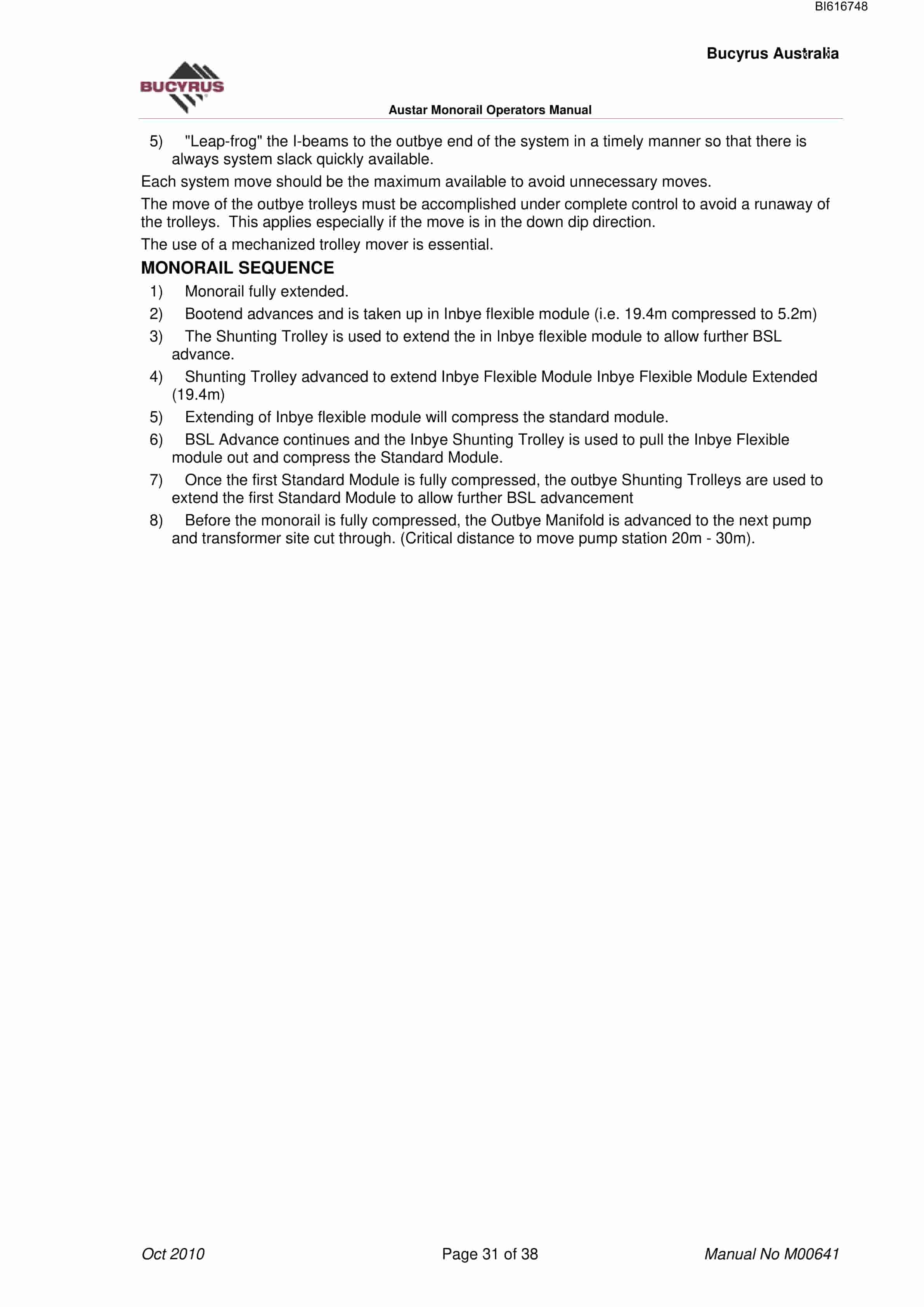
Bucyrus Austar Monorail Technical Manual BI616748
$30.00
- Type Of Manual: Technical Manual
- Manual ID: BI616748
- Number of Pages: 39
- Size: 3.9MB
- Format: PDF
Product details
-
Model List:
- Austar Monorail
- 1. M00641.pdf
- 1.1. General Safety
- 1.1.1. Residual Risk
- 1.1.2. Supplementary Regulations
- 1.1.3. PERSONNEL
- 1.1.3.1. Operation and maintenance
- 1.1.3.2. Qualification
- 1.1.4. USE IN CONFORMANCE WITH SPECIFICATIONS
- 1.1.5. USE CONTRARY TO SPECIFICATIONS
- 1.1.6. SAFETY INSTRUCTIONS
- 1.1.6.1. Basic principles
- 1.1.6.2. Lighting
- 1.1.6.3. Signalling Systems and Protective Devices
- 1.1.6.4. Emergency Stop
- 1.1.6.5. Support Lock-out Switch
- 1.1.6.6. Moving Parts
- 1.1.7. STORAGE AND TRANSPORT
- 1.1.8. HYDRAULICS
- 1.1.8.1. Handling of Hydraulic Fluids
- 1.1.8.2. Maintenance and Repair
- 1.1.8.3. Permissible Hoses
- 1.1.8.4. Installation of Hydraulic Hoses
- 1.2. Storage and transport
- 1.2.1. STORAGE
- 1.2.1.1. Storing the equipment
- 1.2.2. TRANSPORT
- 1.2.2.1. Before transport
- 1.2.2.2. Transport of the components
- 1.3. Assembly
- 1.3.1. PRIOR TO ASSEMBLY
- 1.3.1.1. Who is allowed to carry out assembly work
- 1.3.1.2. Assembly notes
- 1.4. Introduction
- 1.5. Major Components of Monorail
- 1.5.1. Curved Rail Section
- 1.5.2. INBYE FLEXIBLE MODULE
- 1.5.3. OUTBYE MANIFOLD (OUTBYE FILTER STATION)
- 1.5.4. INBYE MANIFOLD (INBYE FILTER STATION)
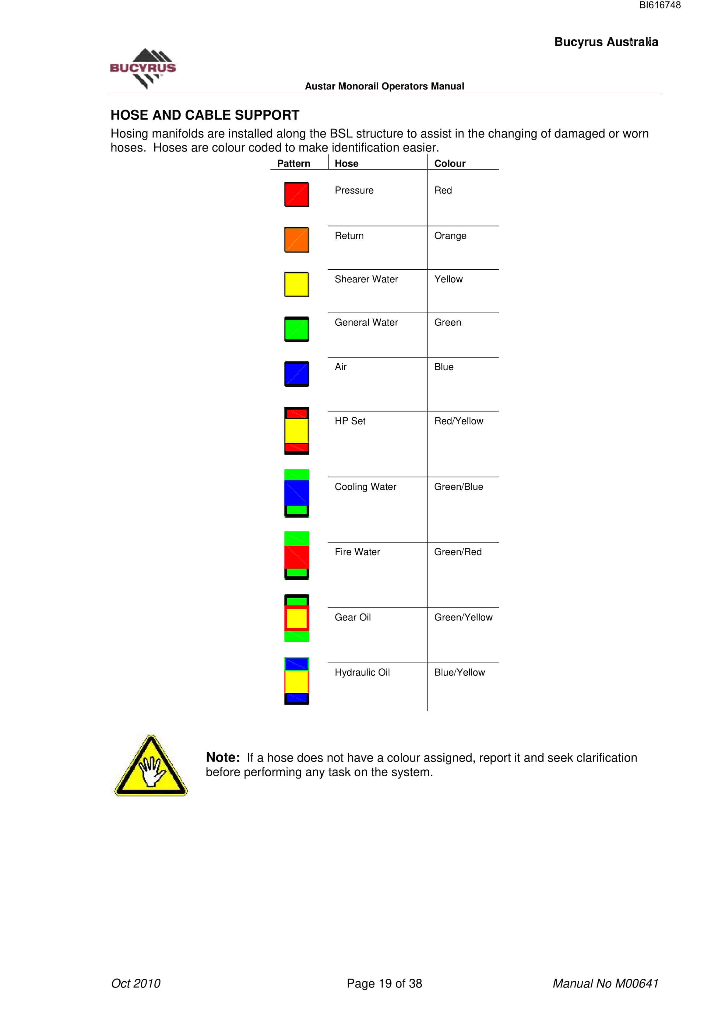
- 1.5.5. HOSE AND CABLE SUPPORT
- 1.5.6. BUMPER TROLLEY
- 1.5.7. CABLE CONNECTOR STATION
- 1.5.8. RAIL STORAGE UNIT
- 1.5.9. MONORAIL TRANSPORT UNITS
- 1.5.10. INSTALLATION PLATFORM
- 1.6. Installation
- 1.6.1. MONORAIL INSTALLATION PLATFORM ADVANCE
- 1.6.2. ROOF HANGERS (DOUBLE MONKEY FACE)
- 1.6.3. INSTALLING RAILS
- 1.6.4. REMOVING RAILS
- 1.6.5. CHANGING HOSES
- 1.6.5.1. Inbye Manifold
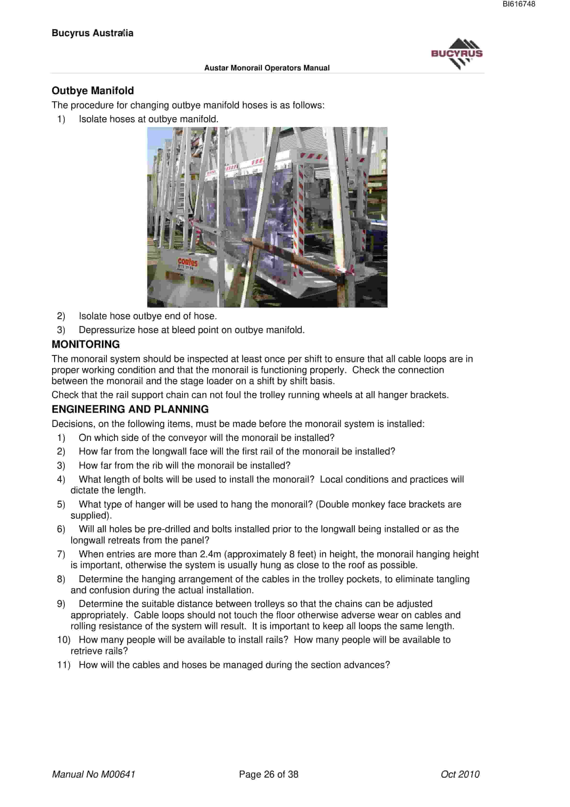
- 1.6.5.2. Outbye Manifold
- 1.6.6. MONITORING
- 1.6.7. ENGINEERING AND PLANNING
- 1.6.8. TROLLEY INSTALLATION
- 1.6.9. CABLE INSTALLATION
- 1.6.10. INSTALLING THE PUSH ARM
- 1.6.11. SYSTEM CHECK LISTS
- 1.6.12. MONORAIL MONITORING
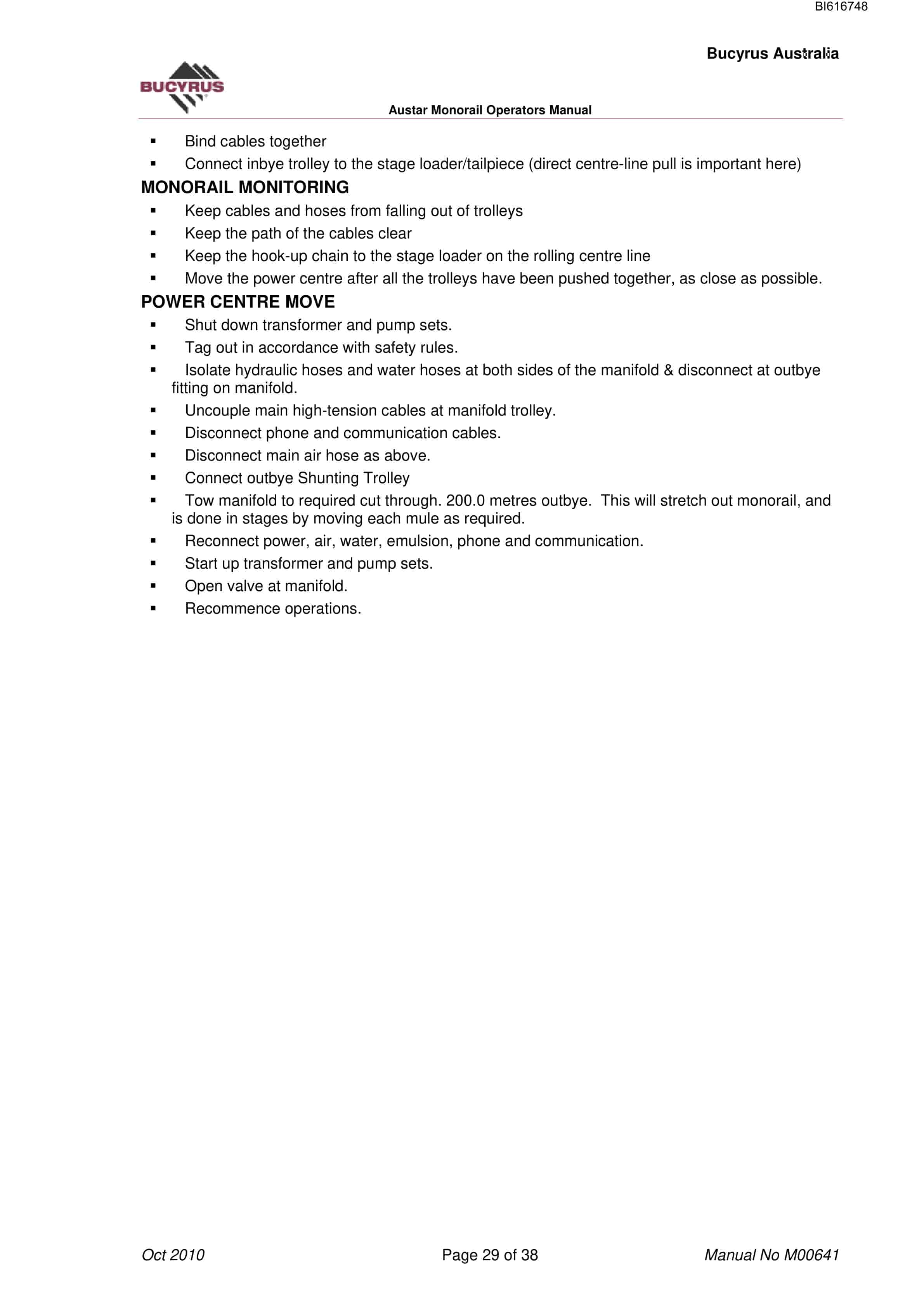
- 1.6.13. POWER CENTRE MOVE
- 1.7. System Operation
- 1.7.1. Inspection – once per shift
- 1.7.2. MONORAIL SEQUENCE
- 1.8. Shunting Trolley
- 1.8.1. TECHNICAL SPECIFICATION
- 1.8.2. OPERATION
- 1.8.2.1. Enrailment of shunting trolley on the rail system
- 1.8.2.2. Brake release
- 1.8.2.3. Brake operation
- 1.8.2.4. Pretensioning of drive wheels
- 1.8.3. SHUNTING TROLLEY INSTALLATION PLATFORM
- 1.9. Monorail Maintenance
- 1.9.1. DAILY MAINTENANCE
- 1.9.1.1. Rails and roof bolts
- 1.9.1.2. Trolley body and brake levers including bolts
- 1.9.1.3. Running and drive wheels
- 1.9.1.4. Couplings and drawbars of attached vehicles and trolleys
- 1.9.1.5. Brake shoes
- 1.9.1.6. Compressed air motor
- 1.9.1.7. Brake release cylinder
- 1.9.1.8. Check Operation of Brake
- 1.9.2. MONTHLY MAINTENANCE
- 1.10. Shunting Trolley Maintenance
- 1.10.1. CHECK DAILY
- 1.10.1.1. Trolley body and brake levers including bolts
- 1.10.1.2. Running and drive wheels
- 1.10.2. COUPLINGS AND DRAWBARS OF ATTACHED VEHICLES AND TROLLEYS
- 1.10.2.1. Brake shoes
- 1.10.3. PNEUMATIC SYSTEM
- 1.10.3.1. Compressed air motor
- 1.10.3.2. Brake release cylinder
- 1.10.3.3. Check Operation of Brake
- 1.10.4. CHECK WEEKLY
- 1.10.5. CHECK MONTHLY
- 1.10.6. PERFORMANCE GRAPH OF SHUNTING TROLLEY 9 KW
- 1.10.7. LUBRICATION SCHEME FOR SHUNTING TROLLEY 9K
- 1.10.7.1. Weekly Maintenance
Related products
-
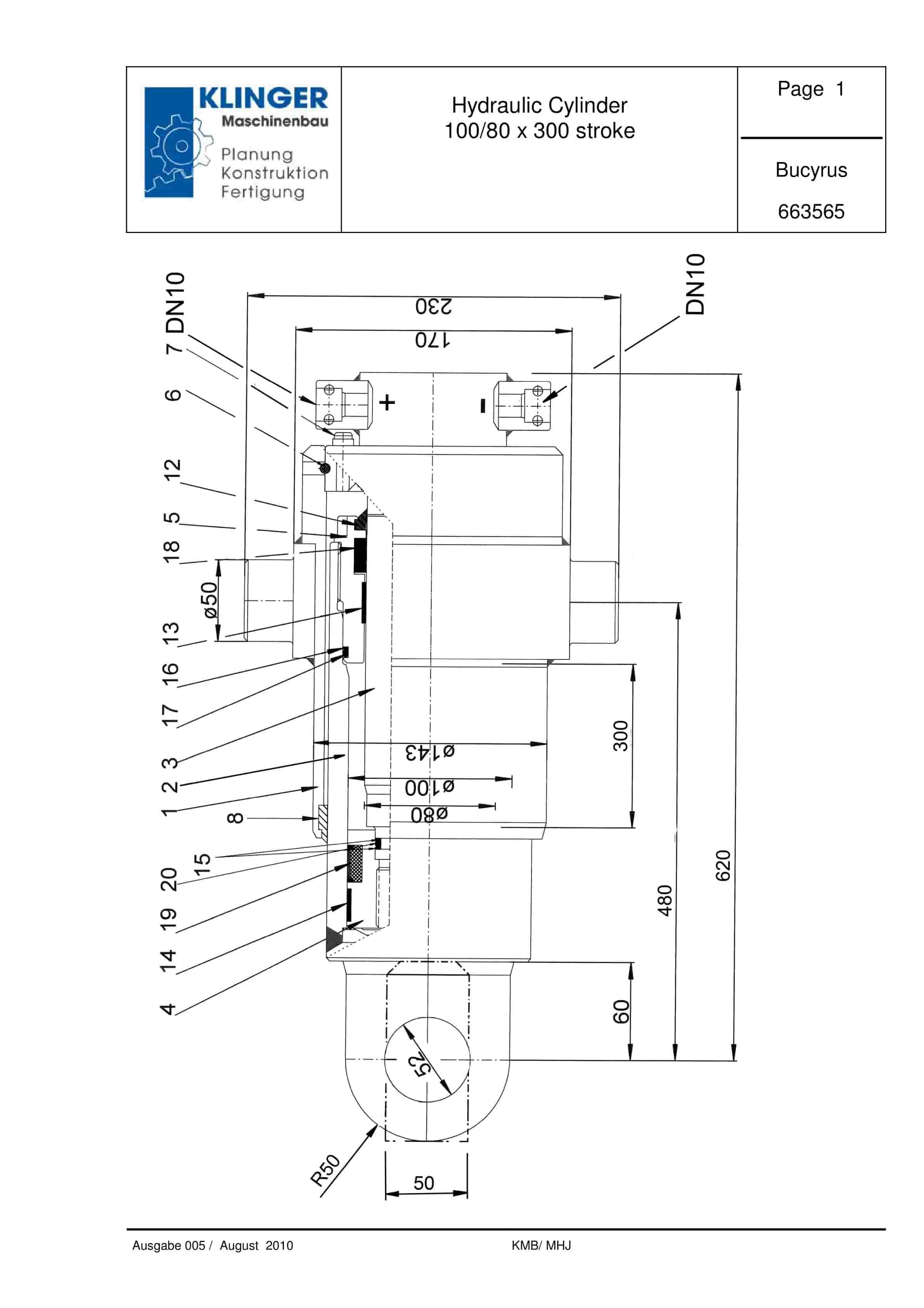
Bucyrus Hydraulic Cylinder 100-80 x 300 Stroke Service Parts List 663565
$30.00 Add to cart -
Bucyrus Continuous Miner Spare Parts List 875339
$30.00 Add to cart -
Bucyrus Continuous Miner Spare Parts List 373608
$30.00 Add to cart -
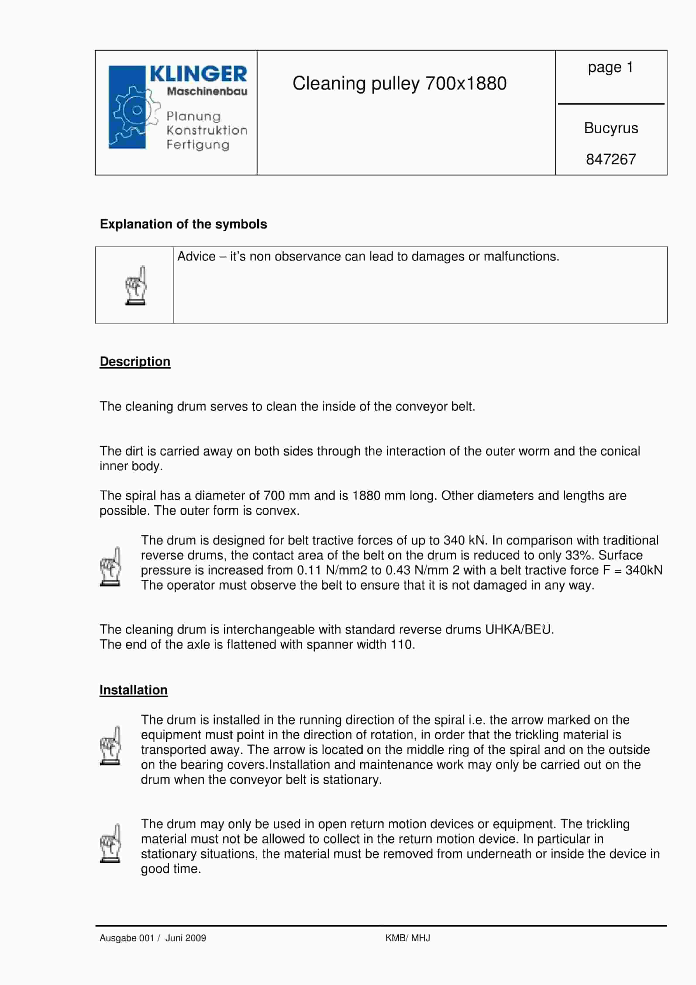
Bucyrus Cleaning Pulley 700 x 1880 Service Parts List 847267
$30.00 Add to cart -
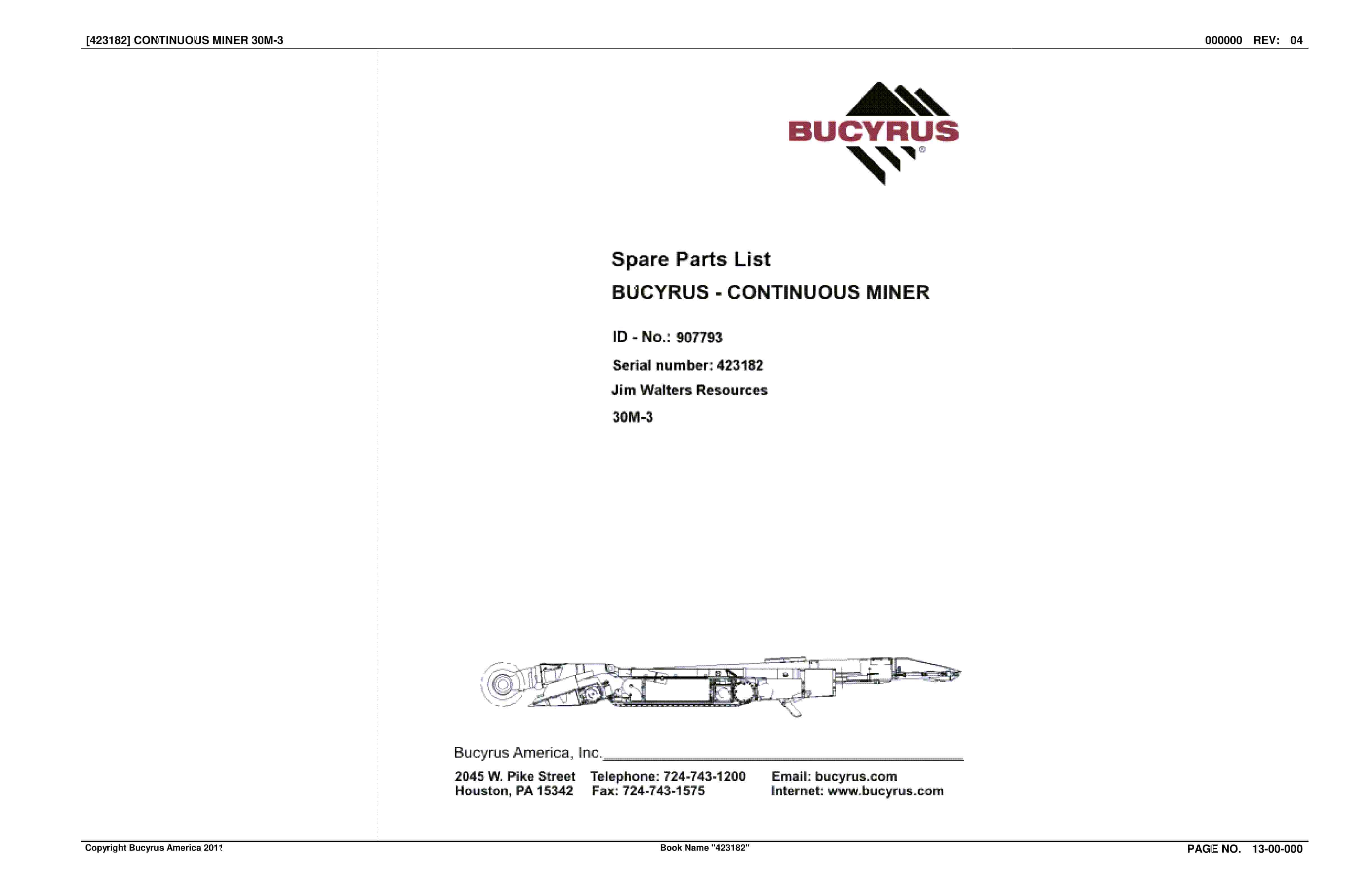
Bucyrus Continuous Miner Spare Parts List 907793
$30.00 Add to cart


