

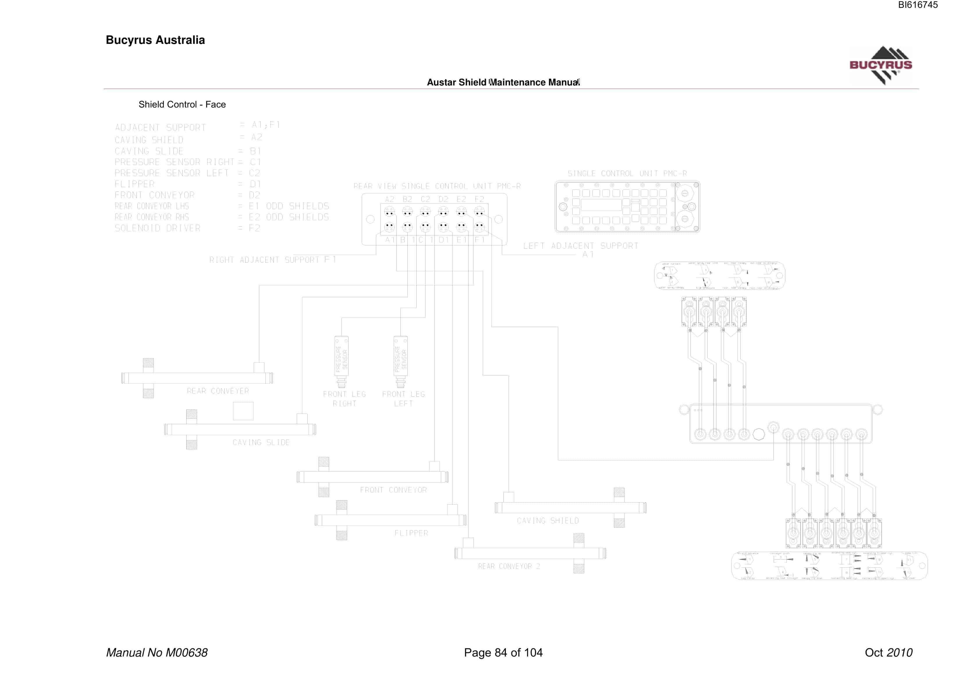
Bucyrus Austar Shield Technical Manual BI616745
$30.00
- Type Of Manual: Technical Manual
- Manual ID: BI616745
- Number of Pages: 105
- Size: 4.1MB
- Format: PDF
Product details
-
Model List:
- Austar Shield
- 1. M00638.pdf
- 1.1. General Safety
- 1.1.1. Residual Risk
- 1.1.2. Supplementary Regulations
- 1.1.3. PERSONNEL
- 1.1.4. OPERATION AND MAINTENANCE
- 1.1.4.1. Qualification
- 1.1.5. USE IN CONFORMANCE WITH SPECIFICATIONS
- 1.1.6. USE CONTRARY TO SPECIFICATIONS
- 1.1.7. SAFETY INSTRUCTIONS
- 1.1.7.1. Basic principles
- 1.1.7.2. Prerequisite
- 1.1.7.3. Lighting
- 1.1.7.4. Signalling Systems and Protective Devices
- 1.1.7.5. Emergency Stop
- 1.1.7.6. Support Lock-out Switch
- 1.1.7.7. Moving Parts
- 1.1.7.8. Automatic Mode
- 1.1.8. STORAGE AND TRANSPORT
- 1.1.9. INSTALLATION
- 1.1.10. OPERATION
- 1.1.11. MAINTENANCE
- 1.1.11.1. Hydraulics
- 1.1.11.2. Handling of Hydraulic Fluids
- 1.1.11.3. Maintenance and Repair
- 1.1.11.4. Permissible Hoses
- 1.1.11.5. Installation of Hydraulic Hoses
- 1.2. Storage and transport
- 1.2.1. STORAGE
- 1.2.1.1. Storage of new equipment
- 1.2.1.2. Exposure to Sunlight
- 1.2.1.3. Natural Ageing
- 1.2.1.4. Moisture and Dirt
- 1.2.1.5. Short Term Storage
- 1.2.1.6. Long Term Storage
- 1.2.1.7. Plastic Deformation
- 1.2.1.8. Random Sample Inspection
- 1.2.1.9. HFA Fluids
- 1.2.2. USED EQUIPMENT
- 1.2.2.1. Corrosion Protection
- 1.2.3. TRANSPORT
- 1.2.3.1. Transport Units
- 1.2.3.2. Points of Attachment
- 1.2.3.3. Temperatures below Freezing
- 1.2.3.4. Electrical and Electronic Components
- 1.2.3.5. Transport Safety Devices and Transport Units
- 1.3. Introduction
- 1.3.1. GENERAL DATA INFORMATION
- 1.3.2. ONE WEB BACK SYSTEM (OWB)
- 1.3.3. BUTTRESS, GATE END AND FACE SHIELDS
- 1.3.4. TOP COAL CAVING
- 1.3.5. Safe Working Areas
- 1.3.6. FRONT WALKWAY
- 1.4. Diagrams
- 1.4.1. HOSING DIAGRAMS
- 1.5. Corrosion Protection
- 1.5.1. EMULSION / WATER / OIL MONITORING
- 1.5.2. QUALITY OF PROCESSED WATER
- 1.5.3. EMULSION VALUES
- 1.6. Hydraulic Bleed Points
- 1.6.1. OPERATION SCREW TYPE
- 1.6.2. OPERATION MANOMETER GAUGE PORT TYPE
- 1.7. Control Unit Troubleshooting
- 1.7.1. NO RESPONSE WHEN SELECTING A FUNCTION
- 1.7.1.1. Corrective Action
- 1.7.2. BYPASSING OR STICKING HIGH OR LOW FLOW VALVES
- 1.7.3. REPLACING HIGH/LOW FLOW VALVE
- 1.7.4. PILOT OPERATED CONTROL VALVE (POCV) REPLACEMENT
- 1.7.5. DOUBLE SOLENOID PILOT VALVE REPLACEMENT
- 1.7.6. CONTROL BLOCK FILTER AND PILOT NON-RETURN VALVE REPLACEMENT
- 1.8. Cylinder Replacement Buttress, face and Gate
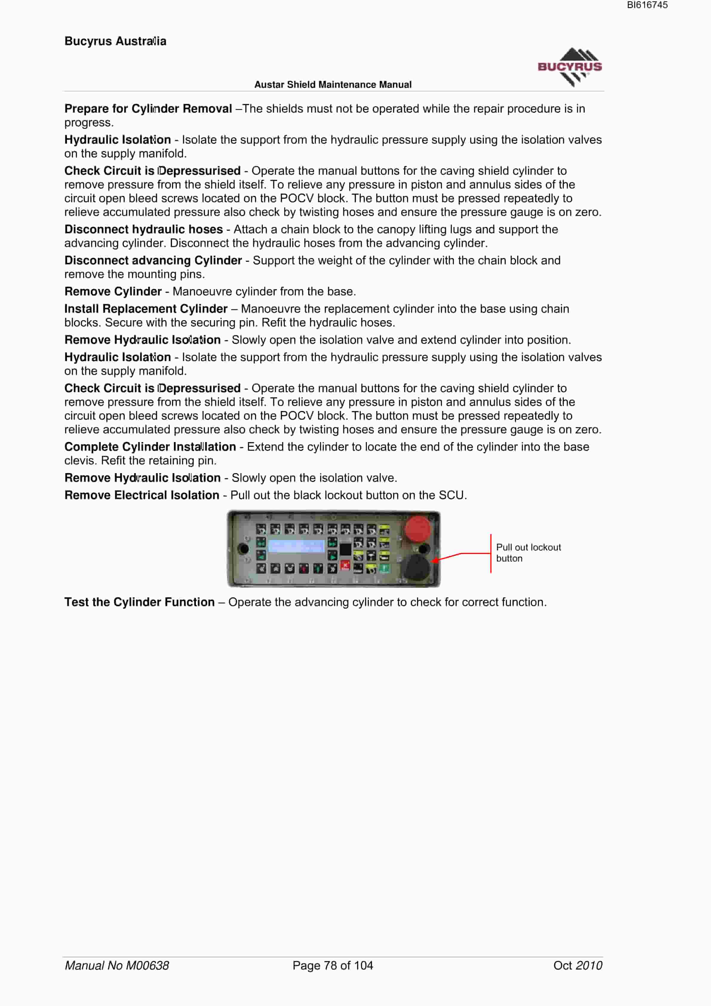
- 1.8.1. ADVANCING CYLINDER REPLACEMENT
- 1.8.2. LEG CYLINDER REPLACEMENT
- 1.8.3. BASE CYLINDER REPLACEMENT
- 1.8.4. GATE SHIELD GOAF CANOPY LEG REPLACEMENT
- 1.8.5. GATE SHIELD FRONT CANOPY TILT CYLINDERS
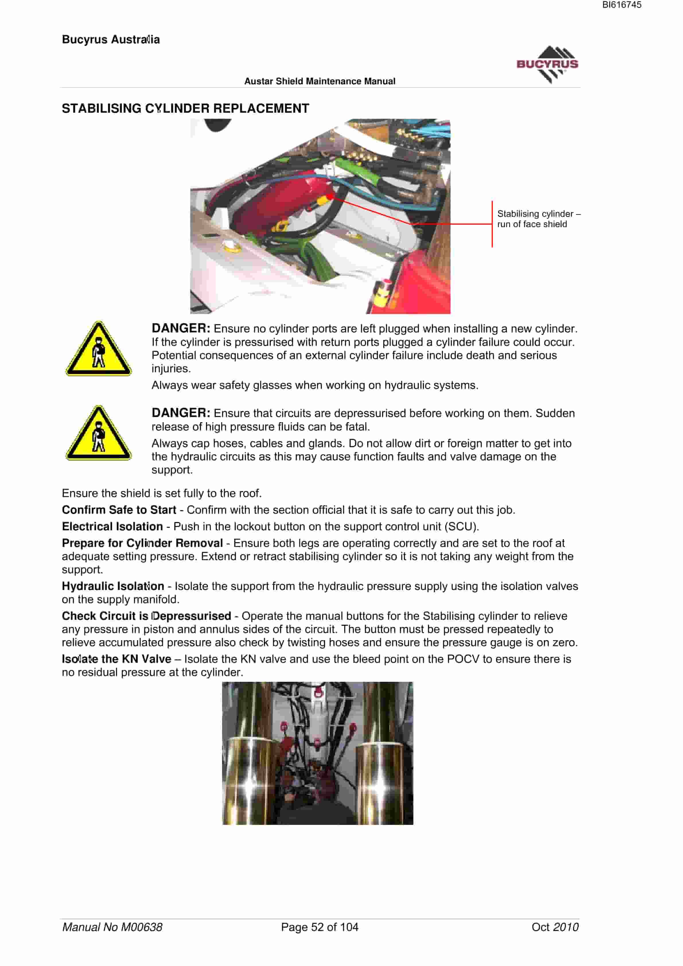
- 1.8.6. STABILISING CYLINDER REPLACEMENT
- 1.8.7. SIDE SHIELD CYLINDER REPLACEMENT
- 1.8.8. CAVING DOOR SLIDE CYLINDER REPLACEMENT
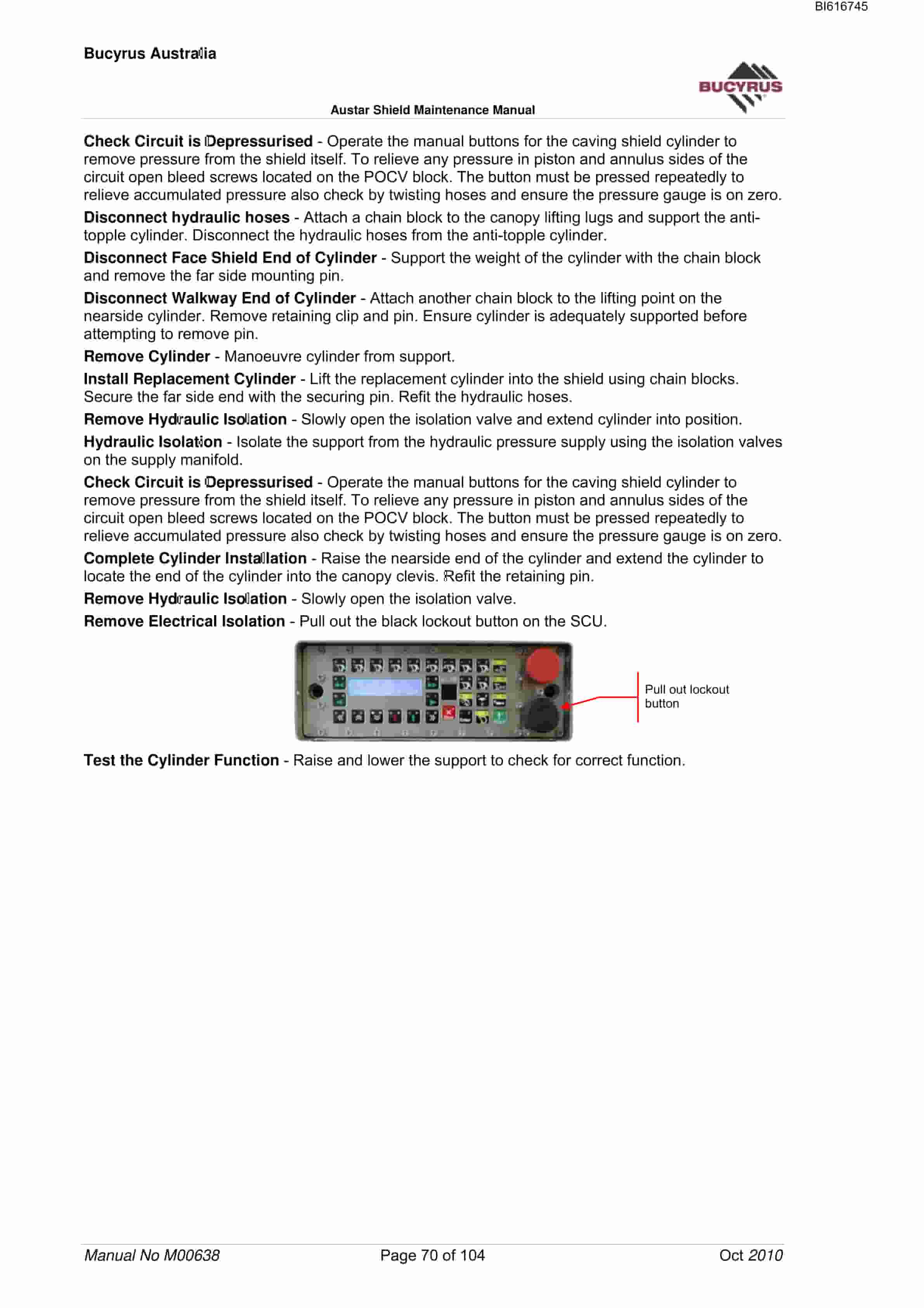
- 1.8.9. CAVING SHIELD CYLINDER REPLACEMENT
- 1.8.10. REAR AFC ADVANCING CYLINDER REPLACEMENT
- 1.8.11. FLIPPER SLIDE CYLINDER REPLACEMENT – GATE
- 1.8.12. FLIPPER CYLINDER REPLACEMENT
- 1.8.13. BUTTRESS ANTI-TOPPLE CYLINDERS
- 1.8.14. INTER-SHIELD HOSE REPLACEMENT
- 1.9. Cylinder Replacement Roadway Shields
- 1.9.1. ROADWAY LEG CYLINDERS
- 1.9.2. ANTI-TOPPLE CYLINDERS
- 1.9.3. ADVANCING CYLINDER
- 1.10. Shields Maintenance (Electrical System)
- 1.10.1. SCU PORT ASSIGNMENTS
- 1.10.1.1. Face PMC-R Port Assignments
- 1.10.1.2. Gate End PMC-R Port Assignments
- 1.10.1.3. Buttress PMC-R Port Assignments
- 1.10.1.4. Roadway PMC-R Port Assignments
- 1.10.2. SKK CABLES AND POWER SUPPLY TESTING
- 1.10.3. PRESSURE SENSOR INFORMATION
- 1.10.4. Reed Rod Information
- 1.10.5. FAULTY SENSOR INDICATION
- 1.10.6. PMC-R POWER ADAPTOR
- 1.10.7. PMC-R ISOLATION COUPLER
- 1.10.8. REMOTE WARNING LIGHT
- 1.11. Shields Maintenance (Electrical) Fault Finding
- 1.11.1. POWER GROUP WITHOUT POWER
- 1.11.2. SUPPORT IS NOT OPERATING
- 1.11.2.1. Possible Reason
- 1.11.2.2. Corrective Action
- 1.11.2.3. If no LED on the Solenoid valve operated
- 1.11.2.4. Change the solenoid driver.
- 1.11.3. SINGLE SCU WITHOUT POWER
- 1.11.4. NO SERVER SCU IN THE NETWORK
- 1.11.4.1. Possible Reason
- 1.11.4.2. Corrective Action
- 1.11.5. SINGLE PMC-R REBOOTS ON POWER UP
- 1.11.6. NO HYDRAULIC FLOW PRESSURE
- 1.11.7. SRB AUTO SEQUENCE STOPS
- 1.11.8. NETWORK DROPS OUT DURING OPERATION
- 1.11.9. INCOMPLETE NETWORK
- 1.11.9.1. Broken cable or faulty SCU
- 1.11.10. WHEN OPERATING A SUPPORT FUNCTION, THE POWER DROPS OFF AND RETURNS
- 1.11.11. DURING AUTO SEQUENCE SUPPORT DOES NOT MOVE
- 1.11.12. BANKPUSH NOT COMPLETED
Related products
-
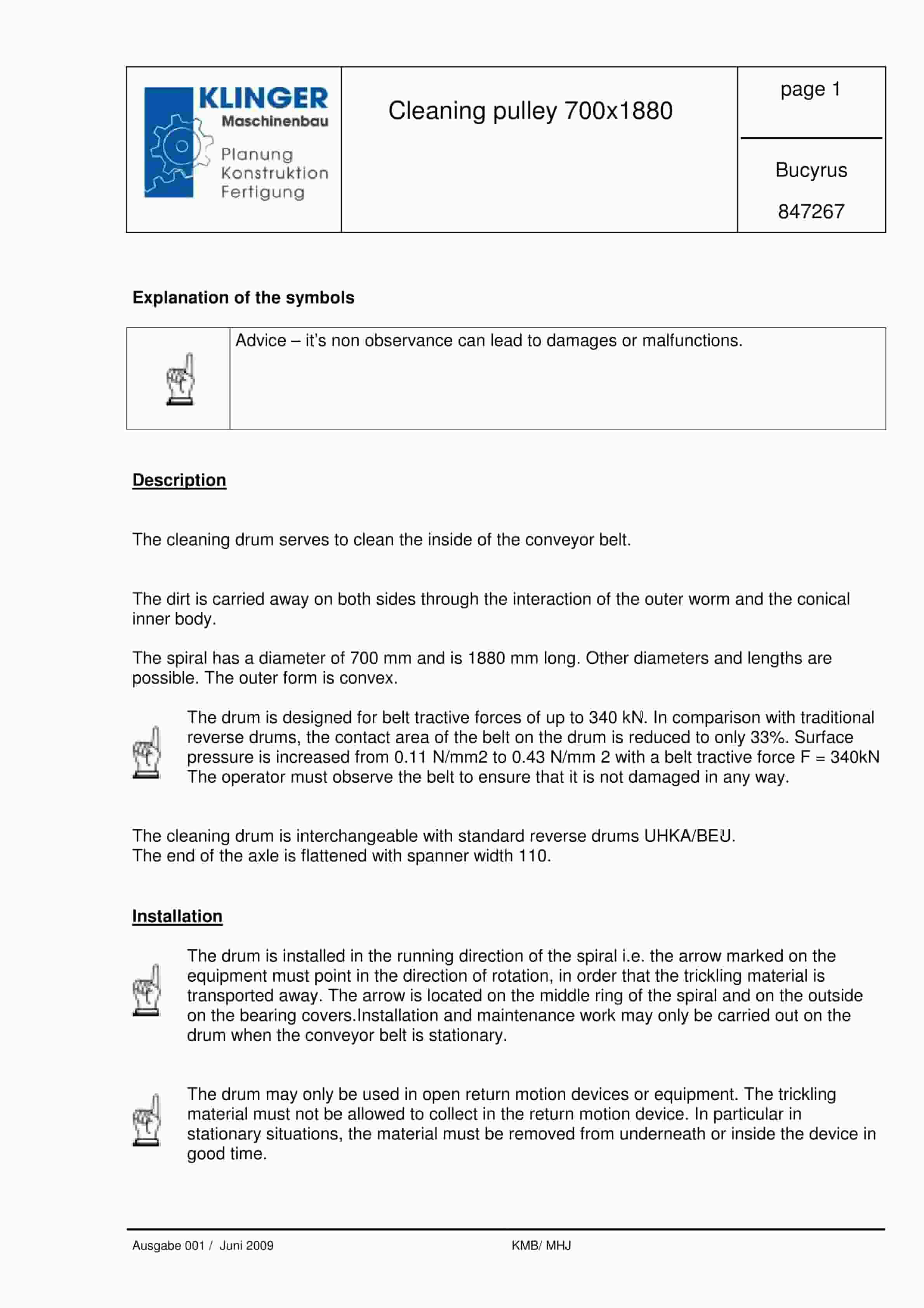
Bucyrus Cleaning Pulley 700 x 1880 Service Parts List 847267
$30.00 Add to cart -
Bucyrus Belt System Spare Parts List 308651
$30.00 Add to cart -
Bucyrus Conveyor Steering Device Technical Description 7427 094 000 BA 00
$30.00 Add to cart -
Bucyrus Continuous Miner Spare Parts List 907783
$30.00 Add to cart -

Bucyrus Fundamentals Of Electrical Engineering Technical Handbook 2440049
$30.00 Add to cart


