
%20Technical%20Manual%20BI620108&url=https://ownersmanualpdf.net/docs/bucyrus-broadmeadow-armoured-face-conveyor-afc-technical-manual-bi620108/&media=https://ownersmanualpdf.net/wp-content/uploads/2026/07/bucyrus-broadmeadow-armoured-face-conveyor-afc-technical-manual-bi620108-1.jpg)
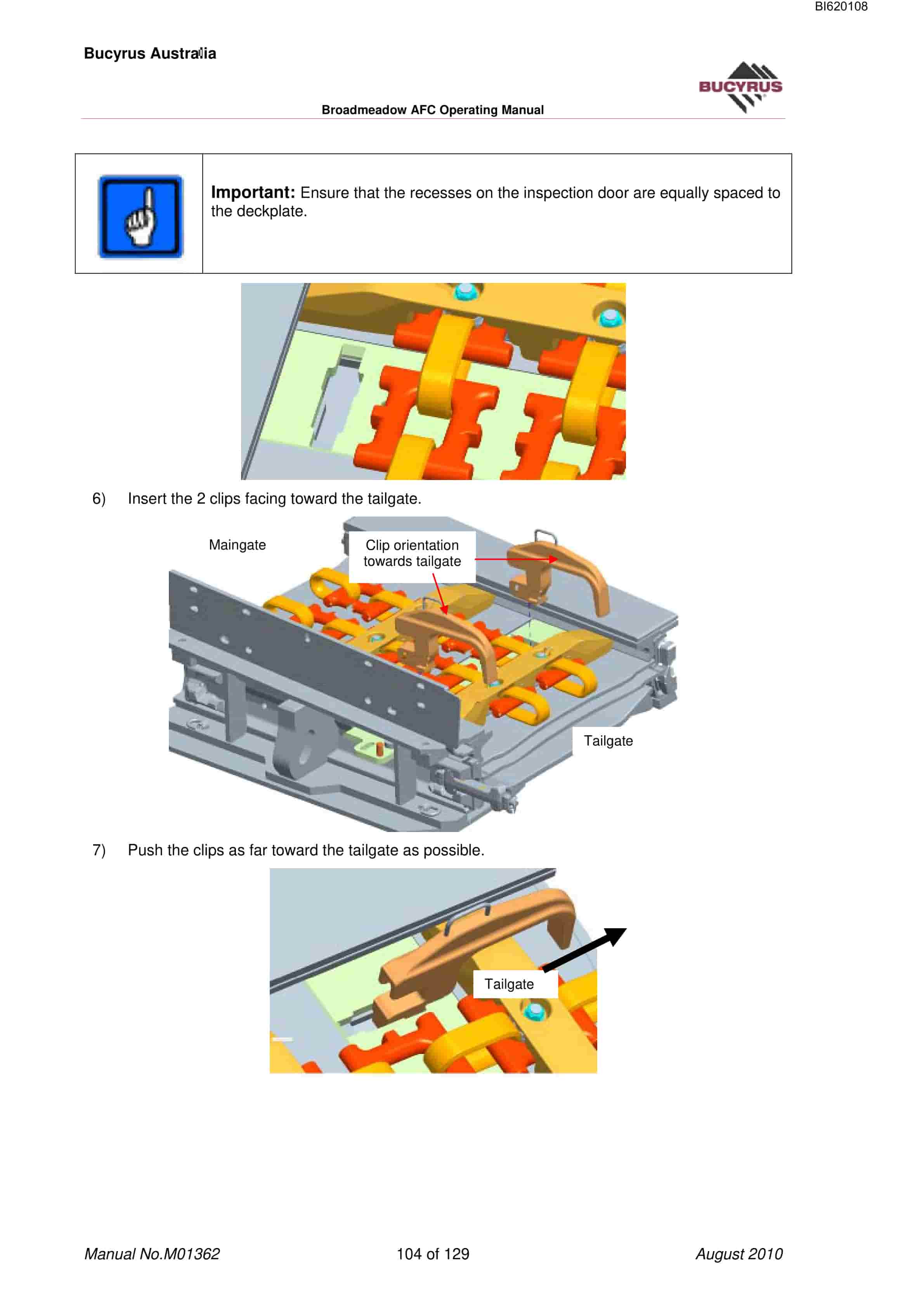
Bucyrus Broadmeadow Armoured Face Conveyor (AFC) Technical Manual BI620108
$30.00
- Type Of Manual: Technical Manual
- Manual ID: BI620108
- Number of Pages: 130
- Size: 7.8MB
- Format: PDF
Product details
-
Model List:
- Broadmeadow Armoured Face Conveyor (AFC)
- 1. M01362.pdf
- 1.1. General Safety
- 1.2. About this Manual
- 1.2.1. BEFORE STARTING WORK
- 1.2.2. WHAT IS THE PURPOSE OF THIS OPERATING MANUAL
- 1.2.2.1. Character and Symbols
- 1.2.3. PERSONNEL
- 1.2.3.1. Erection and Repair
- 1.2.4. OPERATING CONDITIONS
- 1.2.4.1. Intended Use
- 1.2.4.2. Unauthorised Use
- 1.2.5. SAFETY INSTRUCTIONS
- 1.2.5.1. General rules
- 1.2.5.2. Protective equipment
- 1.2.5.3. Condition
- 1.2.5.4. Safety equipment
- 1.2.5.5. Information signs
- 1.2.5.6. Emergency-stop
- 1.2.5.7. Secure the conveyor to prevent restarting
- 1.2.5.8. Block working area
- 1.2.5.9. Moving parts
- 1.2.6. STORAGE AND TRANSPORT
- 1.2.6.1. Transport safety device
- 1.2.6.2. Striking device
- 1.2.6.3. Floor conveying device
- 1.2.7. ERECTION AND COMMISSIONING
- 1.2.7.1. Inclined storage
- 1.2.7.2. Environmental acceptability
- 1.2.8. OPERATION
- 1.2.9. MAINTENANCE AND REPAIR
- 1.2.9.1. Replacing parts
- 1.2.9.2. Original parts
- 1.2.9.3. Lifting points
- 1.2.9.4. Safety equipment
- 1.2.10. HYDRAULICS
- 1.2.10.1. Handling of Hydraulic Fluids
- 1.2.10.2. Maintenance and Repair
- 1.2.10.3. Permissible Hoses
- 1.2.10.4. Installation of Hydraulic Hoses
- 1.3. Storage and Transport
- 1.3.1. STORAGE
- 1.3.1.1. Corrosion protection
- 1.3.1.2. No direct exposure to sunlight
- 1.3.1.3. Moisture and dirt
- 1.3.1.4. Short-term storage
- 1.3.1.5. Long-term storage
- 1.3.1.6. Natural ageing
- 1.3.1.7. Protection against frost damage for oil cooling
- 1.3.2. TRANSPORT
- 1.3.2.1. Load Units Dimensions and Weights
- 1.3.2.2. Before Transport
- 1.3.2.3. Temperatures below freezing
- 1.3.2.4. Antifreeze Measures for Oil Cooler
- 1.3.2.5. Electrical and electronic components
- 1.4. Isolation
- 1.4.1. HYDRAULIC BLEED POINTS
- 1.4.2. AFC AND BSL
- 1.5. Armoured Face Conveyor
- 1.5.1. MAINGATE DRIVE
- 1.5.2. MAINGATE DRIVE MODULE
- 1.5.3. PANLINE
- 1.5.3.1. Pan line features
- 1.5.3.2. W Water Cooled Motor
- 1.5.3.3. Cooling Water
- 1.5.3.4. Hydraulic Slow Run Device
- 1.5.4. MRKR 65/1300/1500 MAINGATE DRIVE FRAME
- 1.5.4.1. Drive Sprocket
- 1.5.4.2. BSL Return Sprocket
- 1.5.4.3. Maingate Drive Auto Greasing
- 1.5.5. TAILGATE DRIVE
- 1.5.5.1. Tailgate Drive Module
- 1.5.5.2. Cooling Water
- 1.5.5.3. Hydraulic Slow Run Device
- 1.5.6. MRHS-65/1300-PF6 TENSIONABLE TAILGATE DRIVEFRAME
- 1.5.6.1. Tensioning Controls
- 1.5.6.2. Drive Sprocket
- 1.5.6.3. Tailgate Drive Auto Greasing
- 1.6. GRADIENT PANS
- 1.6.1. INSTALLING BOLTED DOGBONE CONNECTORS
- 1.7. CONTROL MONITORING STATION
- 1.8. AFC PF6/1342 – 1756 PAN LINE
- 1.8.1. LINE PANS
- 1.8.2. INSPECTION PANS
- 1.8.3. REROUTING PANS
- 1.8.4. MID-FACE PANS
- 1.8.5. SPILLPLATES
- 1.8.5.1. Importance of Alignment and Butting of Pans during Installation
- 1.8.5.2. Threading the Bottom Race
- 1.8.5.3. Cleaning the Bottom Race
- 1.8.5.4. Pan Weight
- 1.8.5.5. Maintenance spillplate
- 1.8.5.6. AFC Pan Line
- 1.8.6. DOGBONE
- 1.9. AFC CHAIN ASSEMBLY
- 1.9.1. AFC Chain
- 1.9.2. AFC Chain Connectors
- 1.9.3. Chain Locking Device
- 1.9.4. AFC FLIGHTS
- 1.9.5. CORRECT ORIENTATION OF CHAIN
- 1.9.6. AFC CHAIN RAMP (OPTIONAL)
- 1.9.7. CHAIN PULLER ATTACHMENT (OPTIONAL)
- 1.9.8. JUMBOTRACK SHEARER HAULAGE
- 1.10. AFC OPERATION
- 1.10.1. Setting Chain Tension Manually
- 1.10.2. Batch Push Recommendations
- 1.10.3. AFC Snake
- 1.10.4. Cutting Beyond the Tailgate Drive
- 1.10.5. Clearing AFC Blockages
- 1.10.6. Reversing the AFC
- 1.11. CARRY-OUT START, STOP AND SHUT-DOWN PROCEDURES
- 1.11.1. Normal start procedure
- 1.11.2. Temporary Stop
- 1.11.3. Normal shut-down procedure
- 1.12. PMCR CHAIN TENSIONING SYSTEM
- 1.12.1. SYSTEM COMPONENTS
- 1.12.2. OVERVIEW
- 1.12.2.1. Tailgate Driveframe
- 1.12.2.2. Reed Rod
- 1.12.2.3. Pressure Sensor
- 1.12.2.4. Solenoid Driver
- 1.12.2.5. PMCR Control Unit
- 1.12.2.6. Manual Controls
- 1.12.3. OPERATION OF THE PMC-R IN THE CTS
- 1.12.4. CTS Operation Starting Automatic Operation
- 1.12.5. CTS OPERATION STOPPING AUTOMATIC AND MANUAL OPERATIONS
- 1.13. PMC-D System
- 1.13.1. KEYBOARD FUNCTIONS
- 1.13.2. PMC- D SYSTEM START SEQUENCE
- 1.13.3. PMC-D OPERATING ERRORS/WARNINGS
- 1.13.3.1. Stored Error Messages
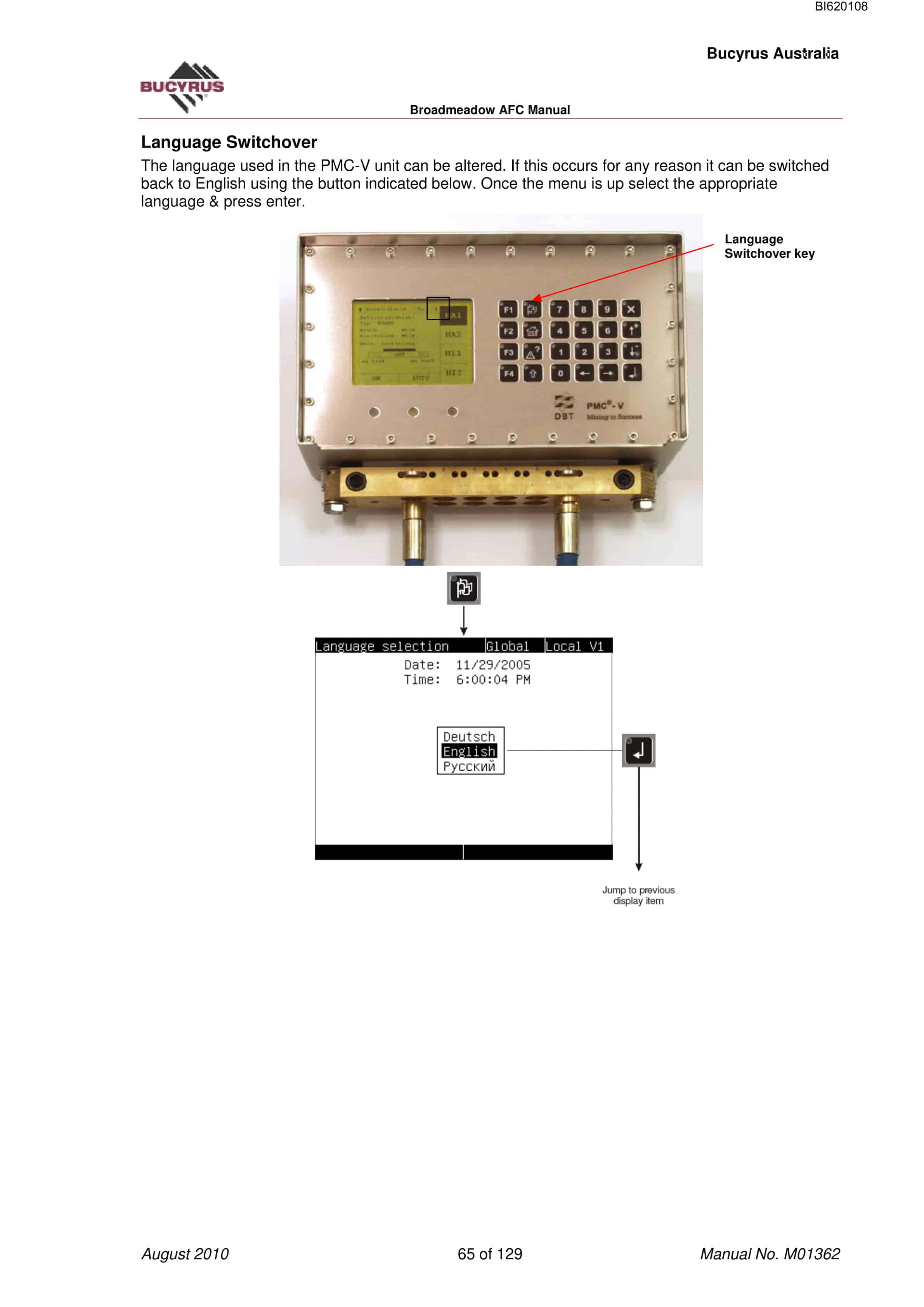
- 1.13.3.2. Language Switchover
- 1.13.3.3. Start Menu
- 1.13.4. CST OPERATING MODES
- 1.13.4.1. Selecting Operating Mode
- 1.13.4.2. Automatic Mode
- 1.13.4.3. Semi-automatic Mode
- 1.13.4.4. Inspection Mode
- 1.13.4.5. Emergency Mode
- 1.13.4.6. Emergency Manual Mode
- 1.13.5. RESETTING THE PMC-D SYSTEM
- 1.13.5.1. Resetting a RED alarm
- 1.13.5.2. Resetting a YELLOW alarm
- 1.13.6. PMC-D OPERATING ERRORS/WARNINGS
- 1.13.6.1. Chain Tensioner
- 1.13.6.2. Cooling Oil Temperature
- 1.13.6.3. Hydraulic Filter
- 1.13.6.4. System Pressure
- 1.13.6.5. Cooling Oil Pressure
- 1.13.6.6. Input Speed (Blockade Overload)
- 1.13.6.7. Output Speed (Blockade)
- 1.13.6.8. Overload
- 1.13.6.9. PMC-D Communication Errors
- 1.13.6.10. Current Measurement
- 1.13.7. CHANGING AFC RUNNING MODES
- 1.13.7.1. Inspection Mode
- 1.13.7.2. Changing to Emergency Mode
- 1.13.7.3. Changing to Emergency Manual Mode (Slow Runner Mode)
- 1.13.7.4. AFC Reverse Procedure
- 1.14. PMC-D Faults
- 1.14.1. PMC-D MESSAGE/ERRORS
- 1.14.2. SENSOR ERRORS
- 1.14.3. CHANGING A PMC-D/V UNIT
- 1.14.4. PMC-D DISPLAY ERROR LIST
- 1.15. The CST (Controlled Start Transmission) System
- 1.15.1. The Start Sequence of the CST system (Auto Mode)
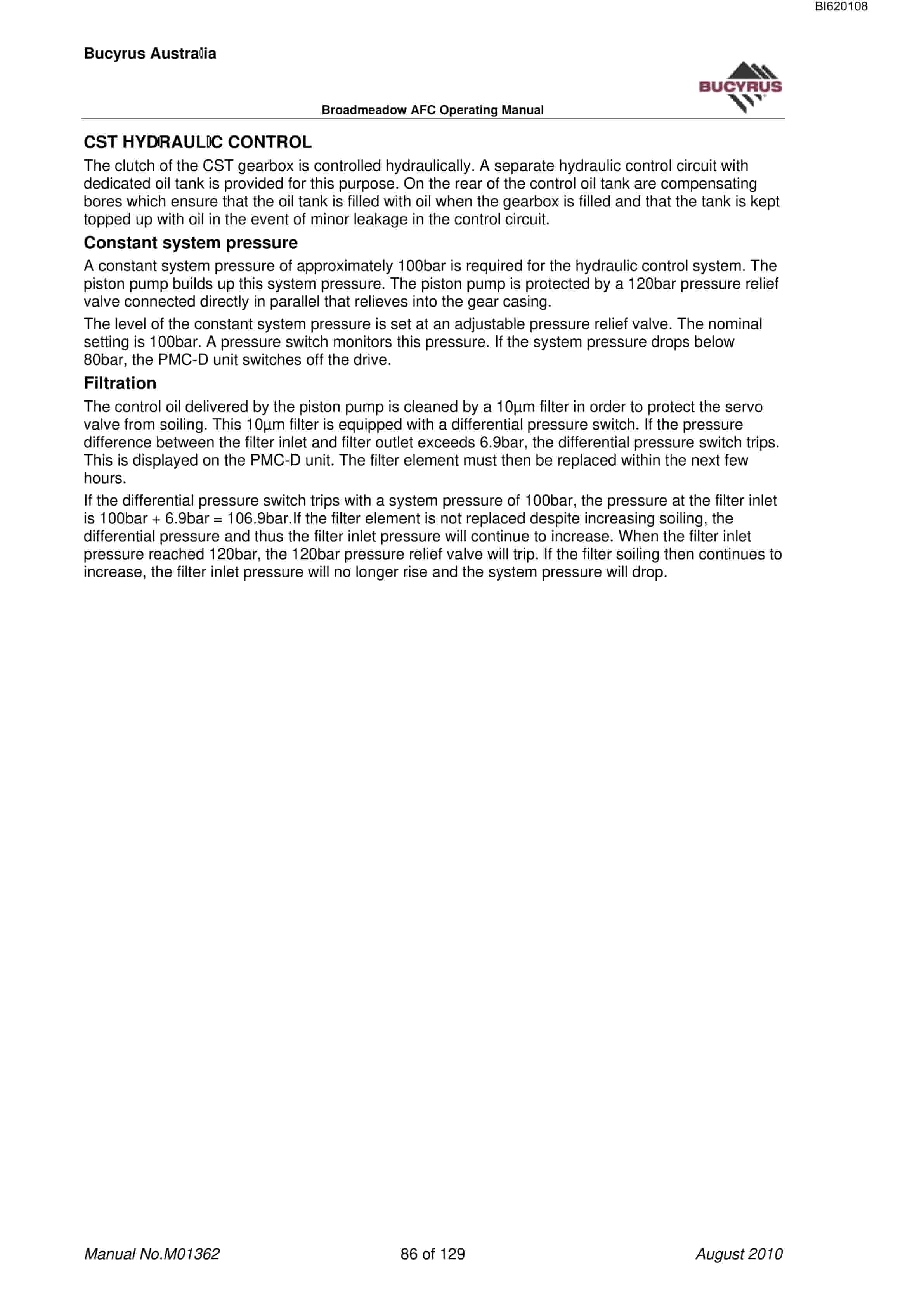
- 1.15.2. CST HYDRAULIC CONTROL
- 1.15.2.1. Constant system pressure
- 1.15.2.2. Filtration
- 1.15.3. CST HYDRAULIC PRESSURE CONTROL DURING PMC-D CONTROLLED MODES OF OPERATION
- 1.15.3.1. Automatic
- 1.15.3.2. Emergency Mode Operation
- 1.15.3.3. Emergency Manual Mode Operation
- 1.15.4. PMC-D CONTROL LOOPS
- 1.15.4.1. Pressure control
- 1.15.4.2. Slip control
- 1.15.4.3. Load balancing
- 1.15.4.4. Full Automatic
- 1.15.4.5. Semi Automatic
- 1.16. CST Trouble Shooting
- 1.16.1. OVERVIEW
- 1.16.2. THE CST GEARBOX CONNECTIONS
- 1.17. Chain Tensioning System Components Operation
- 1.17.1. OPERATING MODES
- 1.17.1.1. CTS Operation Starting Automatic Operation
- 1.17.1.2. CTS Operation Stopping Automatic Manual Operations
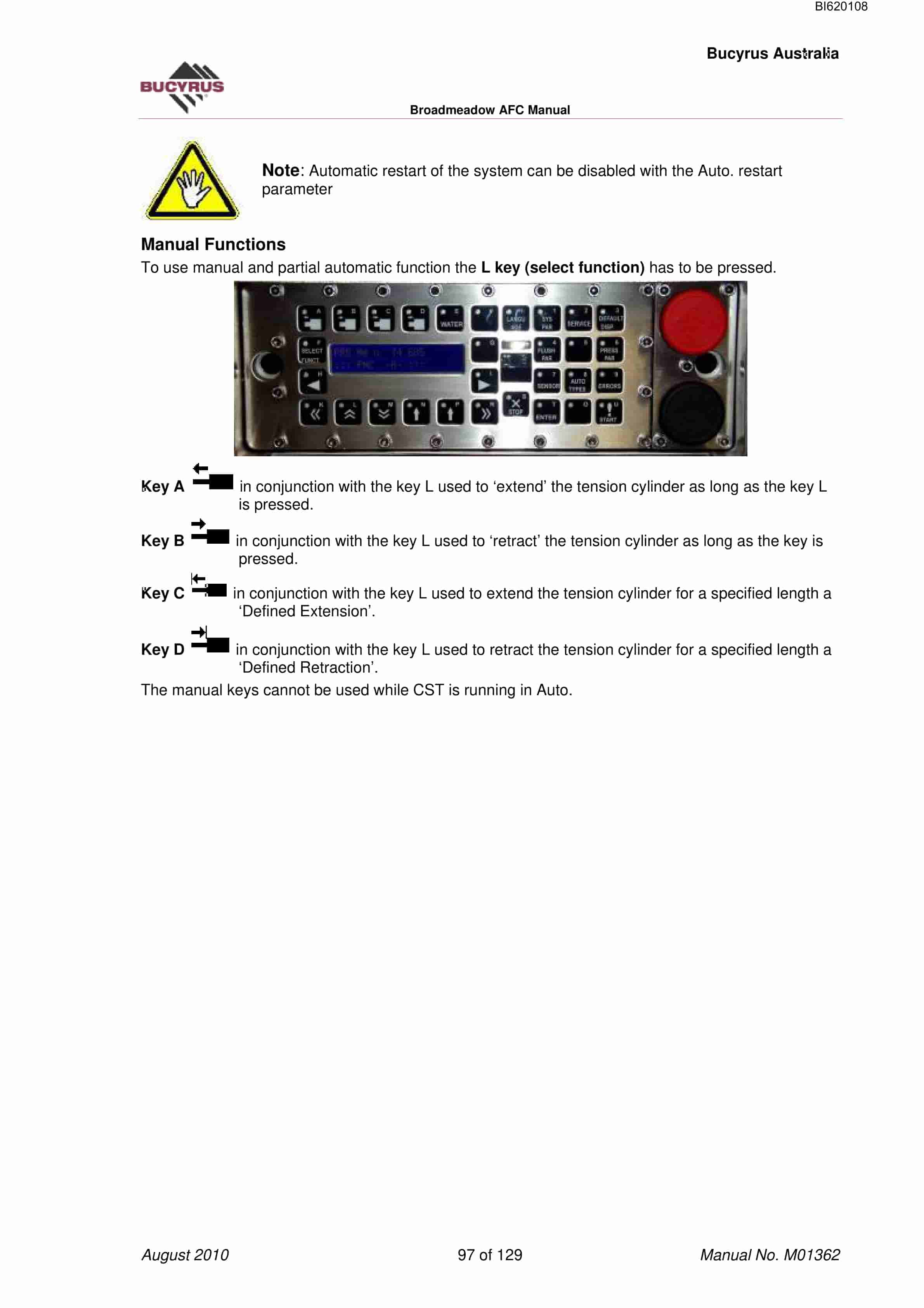
- 1.17.1.3. Manual Functions
- 1.17.1.4. Adjusting Chain Tensioning – No Load
- 1.17.1.5. Adjusting Chain Tensioning – Full Load
- 1.17.2. AFC REVERSE PROCEDURE
- 1.18. AFC Maintenance
- 1.18.1. LUBRICATION
- 1.18.1.1. Approved Lubricants
- 1.18.2. CHAIN ASSEMBLY
- 1.18.2.1. Flights
- 1.18.3. TG DRIVE WEAR PLATES
- 1.18.4. Sprockets and Chain Strippers, Tongue Plates
- 1.18.5. Relief Valve
- 1.18.6. CHAIN LOCKING DEVICE FOR 52X 177 POWER CHAIN
- 1.18.7. Using Slowrunners for Chain Replacement
- 1.18.8. DOGBONE REPLACEMENT PROCEDURE
- 1.18.9. INSPECTION DOORS REMOVAL PROCEDURE
- 1.18.10. JUMBOTRACK RACKBAR REPLACEMENT PROCEDURE
- 1.18.11. AFC Greasing
- 1.19. Gearbox Maintenance
- 1.19.1. OVERVIEW
- 1.19.2. P-45, MAINGATE OIL LEVELS AND QUANTITIES
- 1.19.3. KP-45,MAINGATE AND TAILGATE OIL LEVELS AND QUANTITIES
- 1.19.4. GEARBOX BREATHER REPLACEMENT PROCEDURE
- 1.20. Common Faults and Fault Finding Methods
- 1.20.1. PMC-D SHUTS DOWN CST AND SHOWS BLOCKAGE CONVEYOR
- 1.20.2. PMC-D SHUTS DOWN ON AN OIL TEMPERATURE HIGH ERROR 125
- 1.20.3. PMC-D SHUTS DOWN CST ON A FILTER DIFFERENTIAL PRESSURE HIGH ERROR 122
- 1.20.4. CST SHUTS DOWN AND PMC-V SHOWS A SYSTEM PRESSURE LOW ERROR 123
- 1.20.5. PMC-D SHUTS DOWN CST ON A COOLING OIL PRESSURE LOW ERROR 124
- 1.20.6. THE CLUTCH PRESSURE CONTROL IS ERRATIC OR SLOW
- 1.20.7. THE CLUTCH PRESSURE SENSOR IS NOT WORKING CORRECTLY
- 1.20.8. PMC-D SHUTS DOWN THE CST ON AN INPUT/OUTPUT SPEED SENSOR OR BLOCKAGE CONVEYOR.
- 1.20.9. CST SHUTS DOWN AND PMC-D SHOWS OVERLOAD MOTOR CURRENT ERROR 007
- 1.20.10. CST shuts down and PMC-D shows Chain Tensioner
- 1.20.11. THE GEARBOX LEAKS OIL
Related products
-
Bucyrus Continuous Miner Spare Parts List 907793
$30.00 Add to cart -
Bucyrus Conveyor Steering Device Technical Description 7427 094 000 BA 00
$30.00 Add to cart -
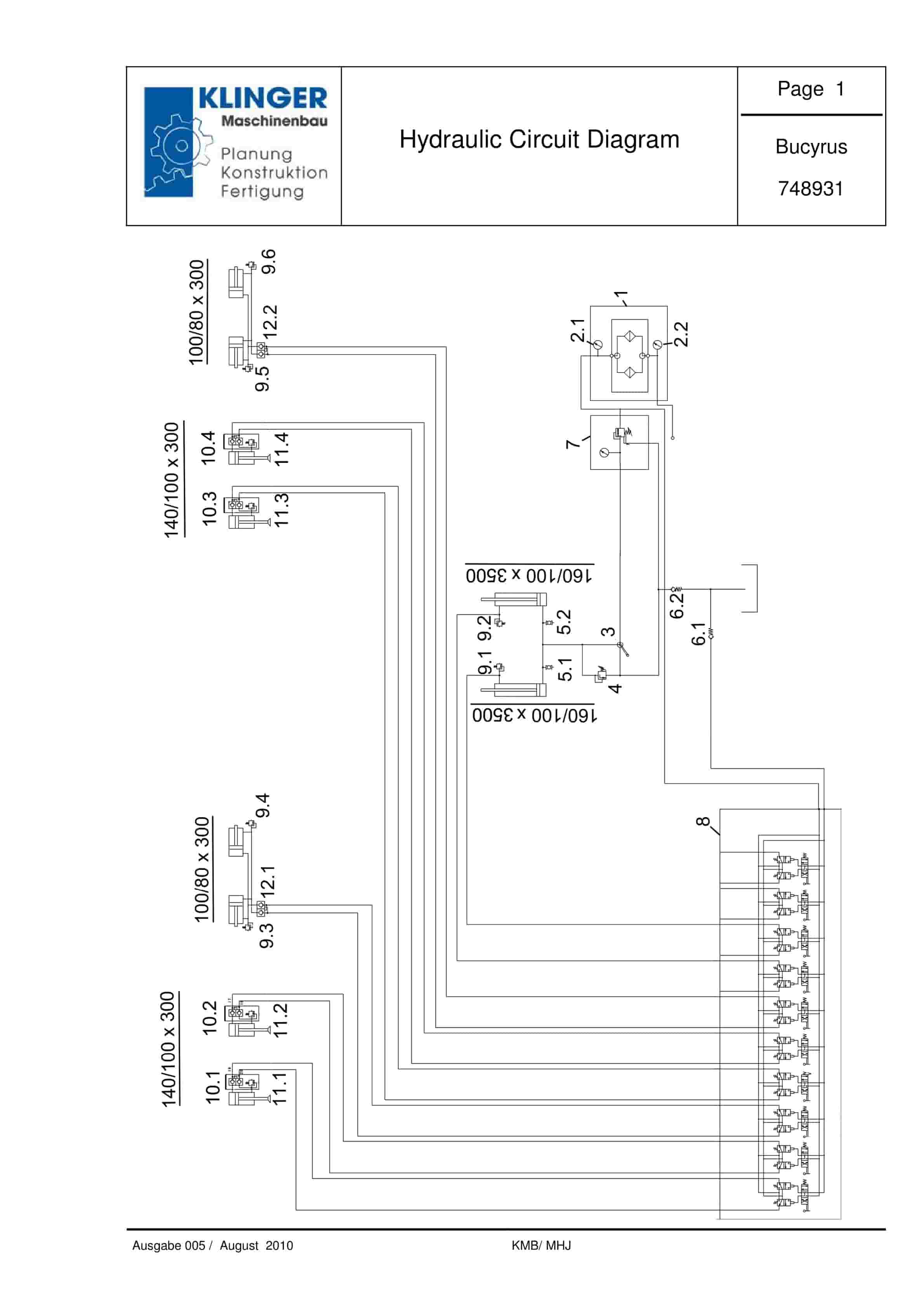
Bucyrus Hydraulic Circuit Diagram Service Parts List 748931
$30.00 Add to cart -
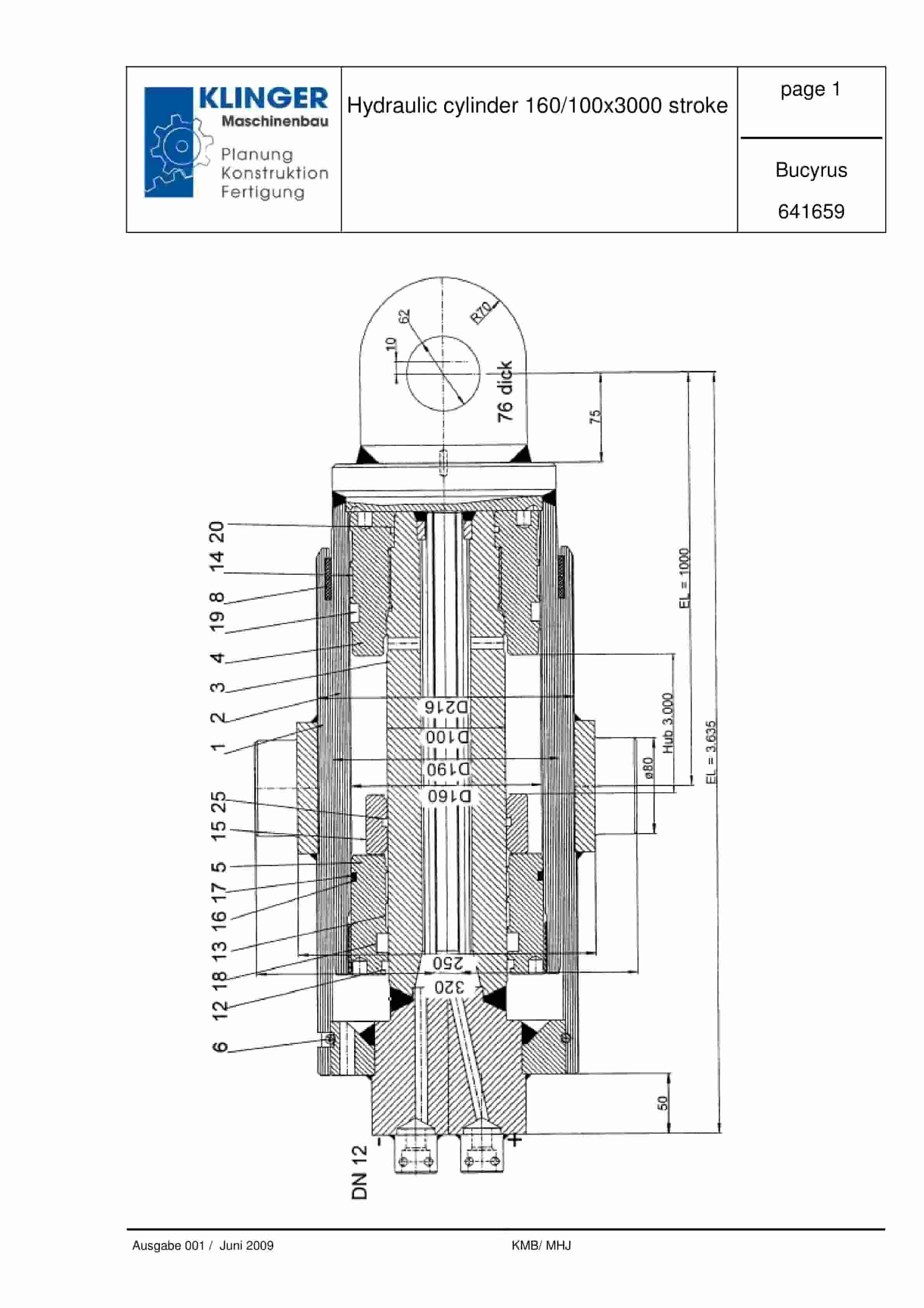
Bucyrus Hydraulic Cylinder 160-100 x 3000 Stroke Service Parts List 641659
$30.00 Add to cart -
Bucyrus Belt System Spare Parts List 316102 – 318743
$30.00 Add to cart


