

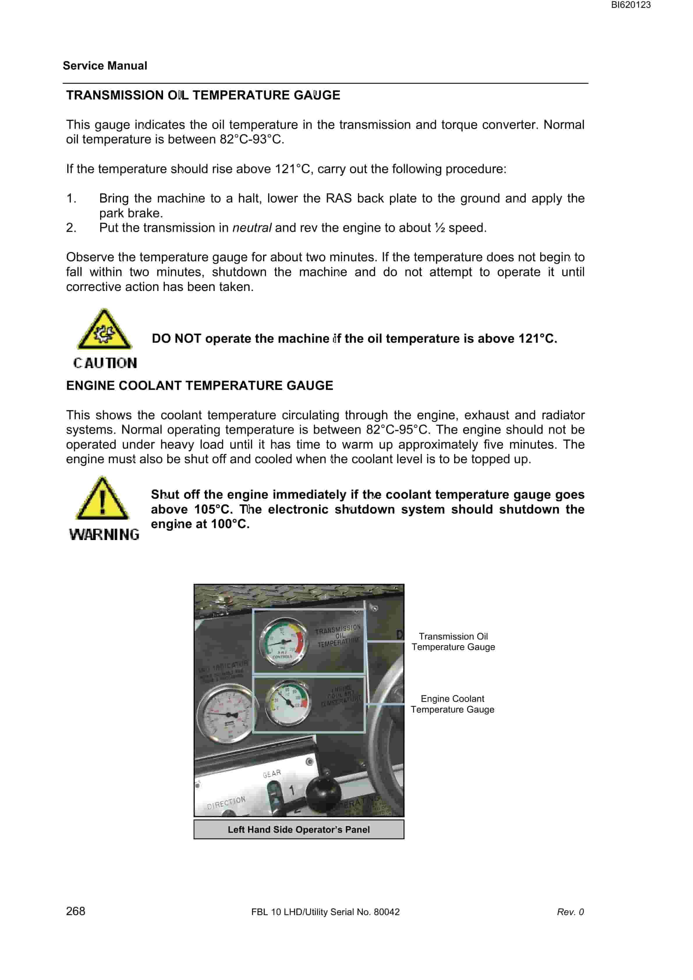
Bucyrus FBL-10 LHD-Utility Technical Manual BI620123
$30.00
- Type Of Manual: Technical Manual
- Manual ID: BI620123
- Number of Pages: 344
- Size: 15.7MB
- Format: PDF
Product details
-
Model List:
- FBL-10 LHD-Utility
- 1. M01379.pdf
- 1.1. Service Manual – Cover Page
- 1.2. Table of Contents
- 1.3. Section 1 General Information
- 1.3.1. Introduction
- 1.3.2. Description
- 1.3.3. SAFETY LABELS AND INSTRUCTIONS
- 1.3.4. Gauge colour code
- 1.3.5. Gauge alarm parameters
- 1.3.6. GENERAL ARRANGEMENT
- 1.3.7. specifications
- 1.3.8. All specifications are subject to change without notice. Always consult BUCYRUS to obtain current information before applying critical loads.
- 1.3.9. Capacities
- 1.3.10. Weight
- 1.3.11. Pneumatic System
- 1.3.12. Lubrication and Fuel Specifications
- 1.3.13. General
- 1.3.14. Fuel Specification Table
- 1.3.15. Fuel Additives
- 1.3.16. Diesel Fuel Relevant Information
- 1.3.17. Fuel handling
- 1.3.18. Low Temperature Effects
- 1.3.19. Exhaust Emissions
- 1.3.20. Engine Maintenance
- 1.3.21. Engine Oil
- 1.3.22. Torque Converter/Transmission Fluid
- 1.3.23. Hydraulic Oil
- 1.3.24. Gear Oil
- 1.3.25. Multi-Purpose EP Grease
- 1.3.26. Drive Coupling Grease
- 1.3.27. Exhaust Conditioner Make Up Tanks
- 1.3.28. Fluid specification table
- 1.3.29. Machine Isolation
- 1.3.30. Engine Isolation
- 1.3.31. Pneumatic Isolation
- 1.3.32. Hydraulic isolation
- 1.3.33. Engine Coolant Isolation
- 1.3.34. Electrical Isolation
- 1.3.35. Articulation Isolation
- 1.3.36. Lift Arm Isolation
- 1.3.37. Exhaust Conditioner Isolation
- 1.3.38. General Safety and Precautions
- 1.3.39. General
- 1.3.40. Packing/Supporting the Machine
- 1.3.41. MAINTENANCE SCHEDULES
- 1.3.42. Maintenance Inspections
- 1.3.43. FBL-10 LHD/Utility Vehicle Lubrication Reference
- 1.3.44. FBL-10 LHD/Utility Vehicle Lubrication Reference
- 1.3.45. FBL-10 LHD/Utility Vehicle Lubrication Reference
- 1.3.46. FBL-10 LHD/Utility Vehicle Lubrication Reference
- 1.3.47. FBL-10 LHD/Utility Vehicle Lubrication Reference
- 1.3.48. FBL-10 LHD/Utility Vehicle Lubrication Reference
- 1.3.49. FBL-10 LHD/Utility Vehicle Lubrication Reference
- 1.3.50. FBL-10 LHD/Utility Vehicle Lubrication Reference
- 1.3.51. Recommended Bolt Torque
- 1.4. Section 2 Engine System
- 1.5. Section 3 Transmission and Drive Train
- 1.6. Section 4 Hydraulic System_Danfoss
- 1.6.1. General description
- 1.6.2. Safety precautions
- 1.6.3. Hydraulic Isolation
- 1.6.4. Pumps and mountings
- 1.6.5. Steering/Brake Pump
- 1.6.6. Main Hydraulic Pump
- 1.6.7. Auxiliary hydraulic pumps
- 1.6.8. Hydraulic tank
- 1.6.9. Checking and filling hydraulic oil
- 1.6.10. Changing hydraulic oil
- 1.6.11. Checking and cleaning filler neck screen
- 1.6.12. Checking and replacing the return filter
- 1.6.13. Steering/brake pump pressure filter
- 1.6.14. Steering circuit
- 1.6.15. Steering accumulator
- 1.6.16. Steering control valve
- 1.6.17. Brake circuit
- 1.6.18. Brake accumulator
- 1.6.19. Brake Valve
- 1.6.20. Brake Heads
- 1.6.21. CONTROL LEVERS
- 1.6.22. Main Control Valve Bank
- 1.6.23. Tilt and Lift Circuits
- 1.6.24. RAS Attach and PTO Circuits
- 1.6.25. Alternator Circuit and Cooling Fan
- 1.7. Section 4 Hydraulic Schematic
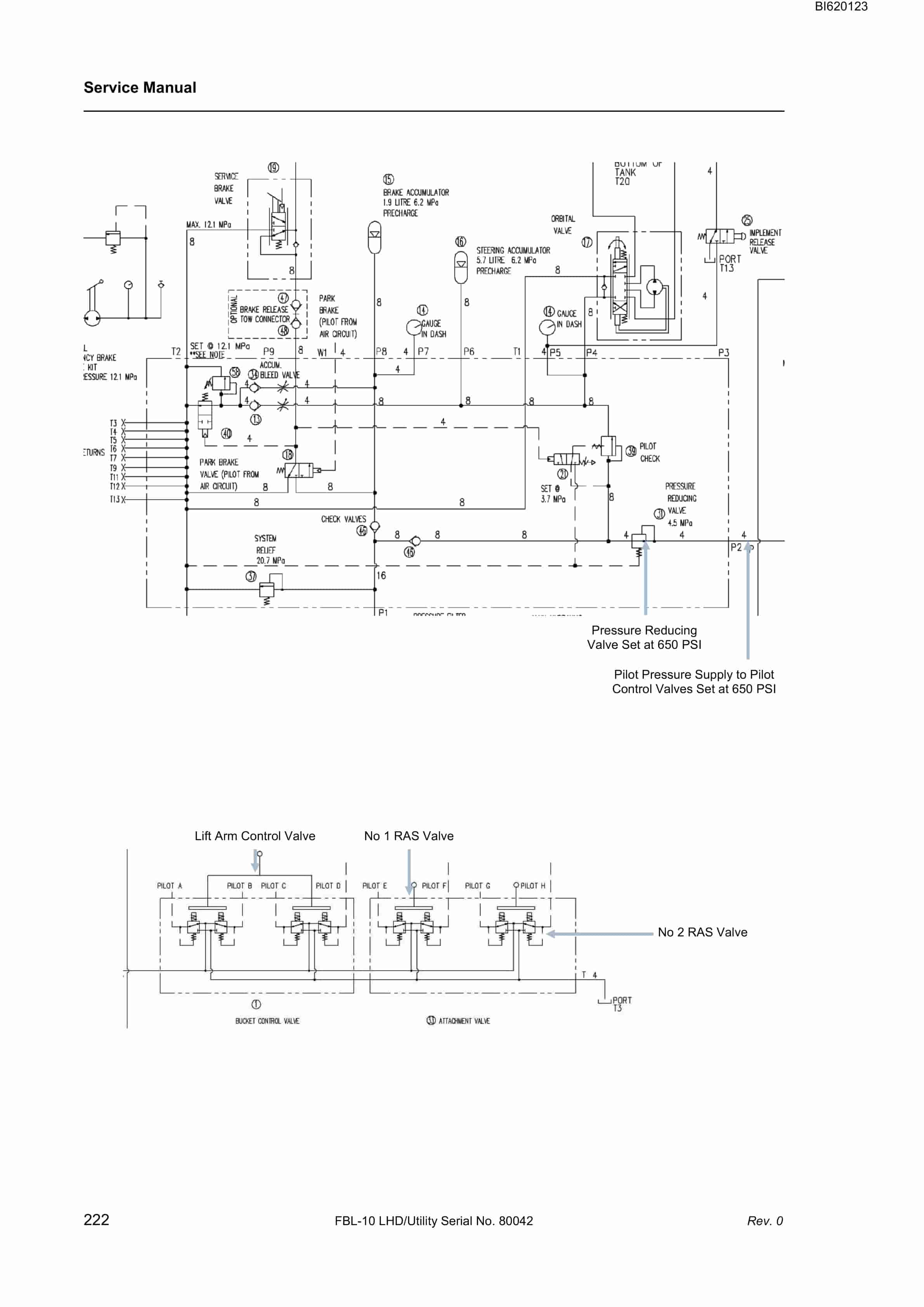
- 1.7.1. Hydraulic schematic
- 1.8. Section 5 Electrics, Instruments and Controls
- 1.8.1. Electrical system
- 1.8.2. General description
- 1.8.3. Safety Precautions
- 1.8.4. Electric lighting components
- 1.8.5. ENGINE SERVICE HOUR meter
- 1.8.6. Electrical system troubleshooting
- 1.8.7. ALTERNATOR AND DRIVE ASSEMBLY
- 1.8.8. GENERAL DESCRIPTION
- 1.8.9. Safety precautions
- 1.8.10. ALTERNATOR ASSEMBLY
- 1.8.11. Alternator Drive Assembly
- 1.8.12. Electronic Shutdown System
- 1.8.13. General Description
- 1.8.14. Power supply
- 1.8.15. Display assemblies
- 1.8.16. General Arrangements
- 1.8.17. switches
- 1.8.18. SENSORS
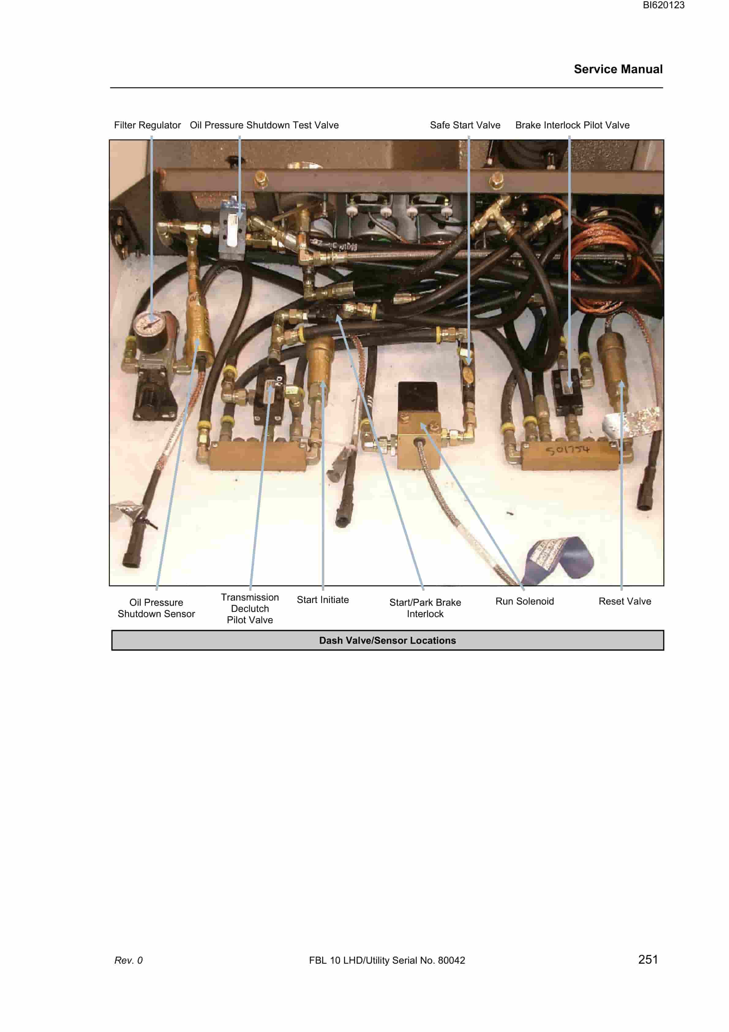
- 1.8.19. Sensor locations
- 1.8.20. INSTRUCTIONS FOR electronic shutdown system METHANE SENSOR HEAD
- 1.8.21. Checks and Calibration of the TX6383 CH4 TROLEX
- 1.8.22. Unit should be in fresh air, or fresh air is to be supplied. The unit should have the GREEN LED illuminated.
- 1.8.23. Check reading. If not zero go to Step 3. If the unit reads zero there is no need to zero. (Go to Step 6).
- 1.8.24. To calibrate zero hold both buttons in for three seconds LED will go to RED which means the unit is in Calibration Mode.
- 1.8.25. Whilst the RED LED is illuminated press and hold the bottom button until the LED is flashing GREEN.
- 1.8.26. Release button and the unit will auto zero, after auto zeroing the unit will go to normal operating mode. The LED will go to GREEN.
- 1.8.27. Turn the zero gas off.
- 1.8.28. Apply the nominal span gas. Allow for sufficient time for reading to be stable. The reading should be 10 of reading or 5 of full scale whichever is least.
- 1.8.29. If reading is outside of tolerance got to the Step 9. If the reading is within the tolerance turn gas off and allow reading to go back to zero. (Go to Step 12)
- 1.8.30. Press and hold both buttons for three seconds. Span gas must be left on at this stage. The LED will go to RED
- 1.8.31. Press and hold the top button until the LED is flashing ORANGE. With the buttons adjust the reading on the display to match that of the nominal gas applied. You have five seconds to press a button. If you do not press a button in this time the unit will go to normal operations.
- 1.8.32. Take gas off the sensor and allow it to go back to zero. Reapply gas to verify the calibration.
- 1.8.33. Let sensor zero in air and turn off gas cylinders. The LED should be back to GREEN.
- 1.8.34. System Operation
- 1.8.35. Testing methane sensor
- 1.8.36. Fault diagnosis guide
- 1.8.37. INSTRUMENTS AND CONTROLS
- 1.8.38. Compartment door
- 1.8.39. Transmission gear control lever
- 1.8.40. Transmission Directional Control Lever
- 1.8.41. Park Brake button
- 1.8.42. FOUR-WAYJOYSTICK control lever
- 1.8.43. No. 2 – TWO-WAY HYDRAULIC Control Lever
- 1.8.44. No. 1 – TWO-WAY HYDRAULIC control lever
- 1.8.45. CONTROL LEVER MAINTENANCE
- 1.8.46. Operators Seat
- 1.8.47. Accelerator Pedal
- 1.8.48. Brake pedal
- 1.8.49. STEERING WHEEL
- 1.8.50. Brake head pressure gauge
- 1.8.51. Brake accumulator pressure gauge
- 1.8.52. Steering accumulator pressure gauge
- 1.8.53. Engine Start Button
- 1.8.54. On/Off Toggle Switch
- 1.8.55. Air pressure gauge
- 1.8.56. Transmission Oil Temperature Gauge
- 1.8.57. Engine Coolant Temperature Gauge
- 1.8.58. Horn button
- 1.8.59. Emergency Fuel Shut Off Valve
- 1.8.60. Air Cleaner Service Indicator
- 1.8.61. Engine SERVICE Hour Meter
- 1.8.62. Engine Oil Pressure Gauge
- 1.8.63. Shutdown System Test Valve
- 1.8.64. ENGINE fuel Primer Pump
- 1.8.65. RAS Pilot lock cylinder release button
- 1.8.66. Attachment quick connects button
- 1.8.67. Emergency Intake Shut Off Valve
- 1.9. Section 6 Frame Components
- 1.10. Section 7 Pneumatic System
- 1.11. Section 8 Attachments
Related products
-
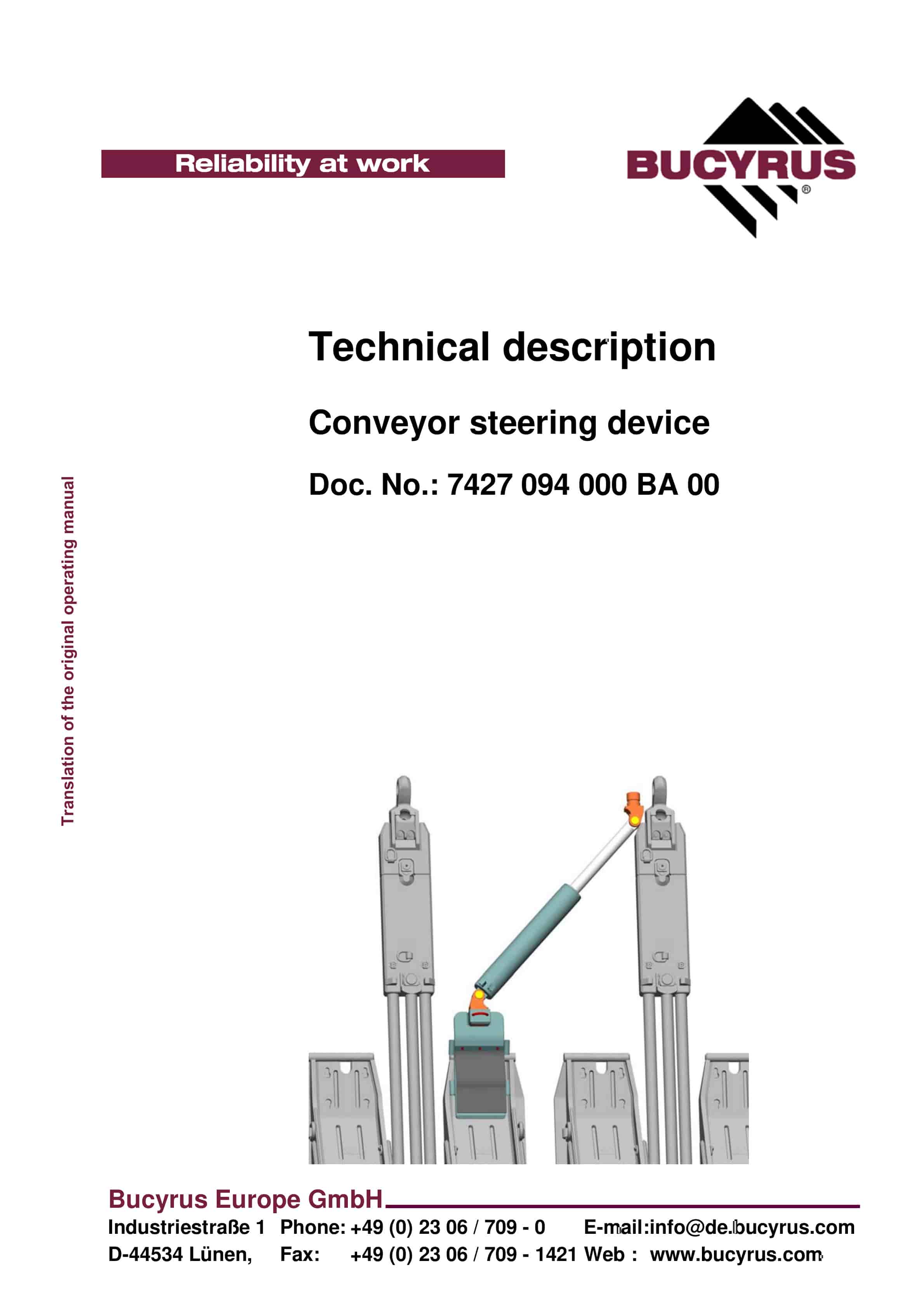
Bucyrus Conveyor Steering Device Technical Description 7427 094 000 BA 00
$30.00 Add to cart -
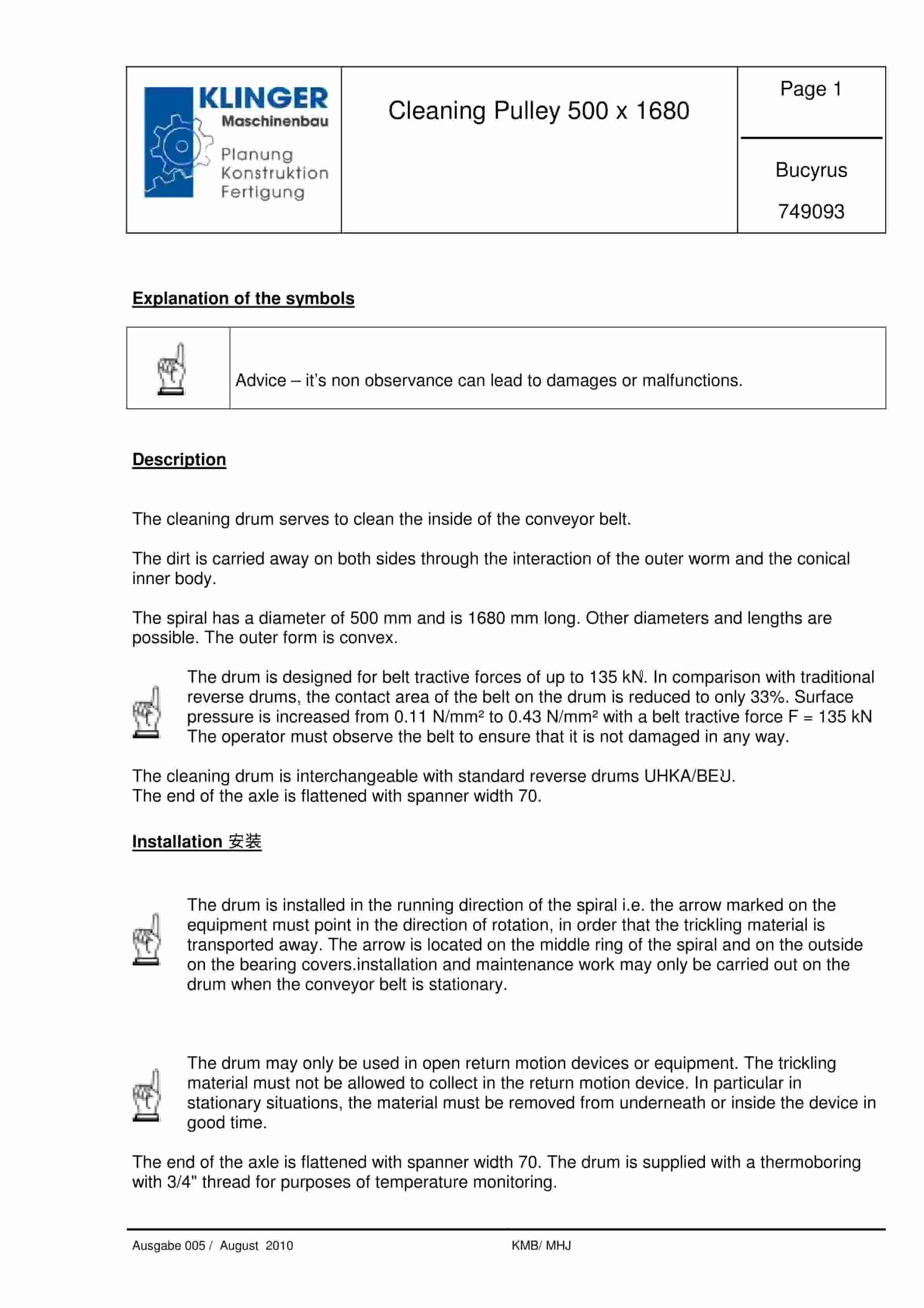
Bucyrus Cleaning Pulley 500 x 1680 Service Parts List 749093
$30.00 Add to cart -
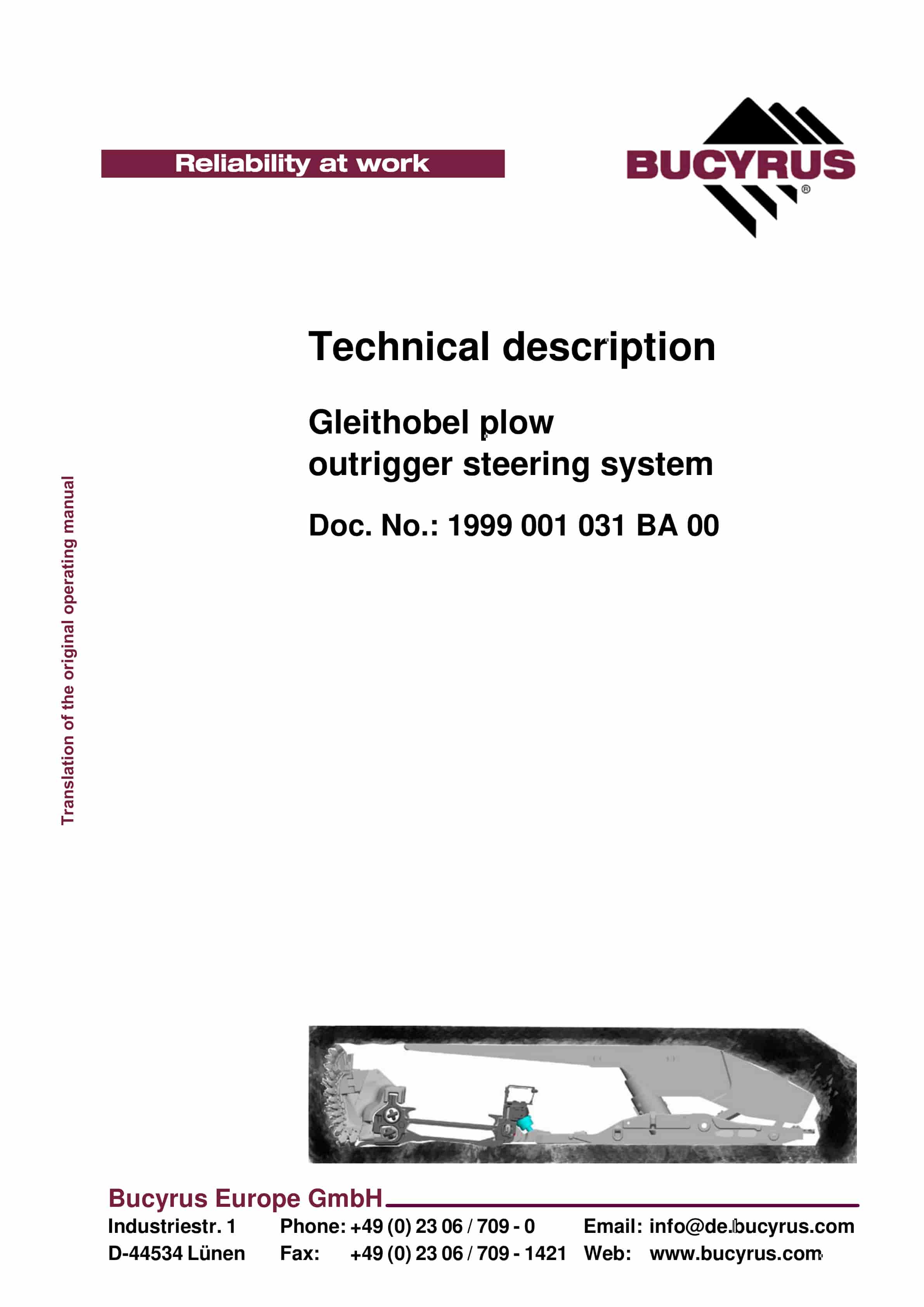
Bucyrus Gleithobel Plow Outrigger Steering System Technical Description 1999 001 031 BA 00
$30.00 Add to cart -
Bucyrus Belt System Spare Parts List 203106
$30.00 Add to cart -
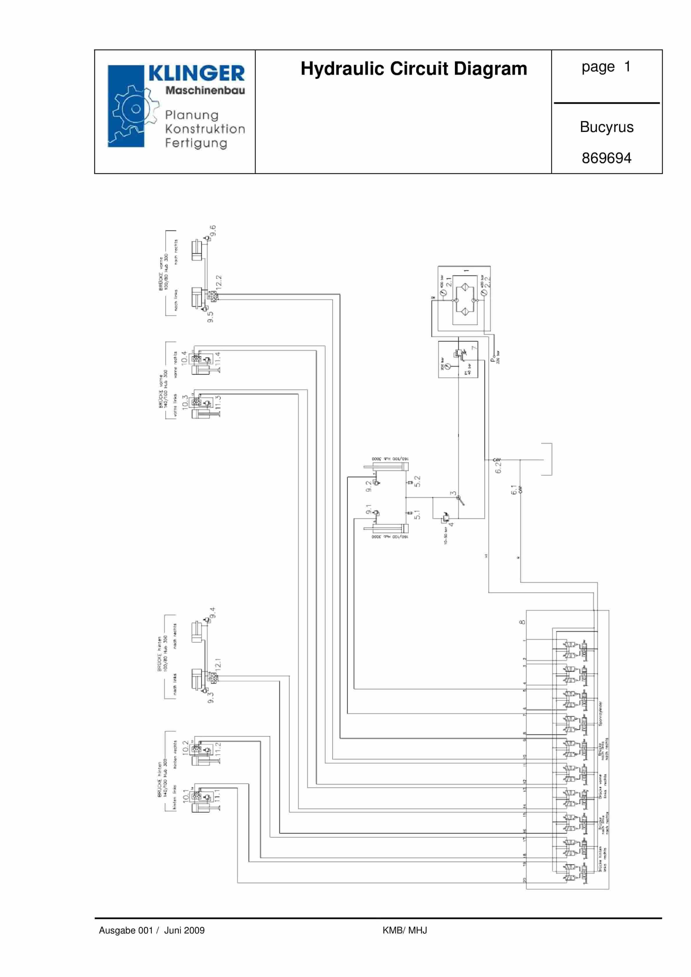
Bucyrus Hydraulic Circuit Diagram Service Parts List 869694
$30.00 Add to cart


