

Bucyrus JLT15021 Technical Manual BI619416
$30.00
- Type Of Manual: Technical Manual
- Manual ID: BI619416
- Number of Pages: 29
- Size: 1.3MB
- Format: PDF
Product details
-
Model List:
- JLT15021
- 1. JLT15021UM-EXT.pdf
- 1.1. JLT15021
- 1.1.1. User manual
- 1.2. Content
- 1.3. General
- 1.3.1. JLT15021
- 1.3.2. Front view
- 1.3.2.1. PC Card lid
- 1.3.2.2. Boot Media lid
- 1.3.2.3. Increase brightness
- 1.3.2.4. Decrease brightness
- 1.3.2.5. Power LED
- 1.3.2.6. Power button
- 1.3.3. Rear view
- 1.3.3.1. Pressure compensator
- 1.3.3.2. Firewire port
- 1.3.3.3. Two USB ports
- 1.3.3.4. Multimedia port
- 1.3.3.5. Keyboard/Mouse port
- 1.3.3.6. Serial port COM1
- 1.3.3.7. Serial port COM2
- 1.3.3.8. RJ45 Ethernet port
- 1.3.3.9. Power cable
- 1.3.3.10. Features
- 1.3.3.11. Accessories
- 1.3.3.12. Function buttons
- 1.4. Using the JLT15021
- 1.4.1. Turning on the JLT15021
- 1.4.2. Shutting down the JLT15021
- 1.4.3. Screen brightness
- 1.4.4. Touch screen
- 1.4.5. Selecting
- 1.4.6. Double click
- 1.4.7. Drag object
- 1.4.8. Calibrate
- 1.4.8.1. Open the Control Panel from the Windows Start menu.
- 1.4.8.2. Double-tap the Pointer Devices icon.
- 1.4.8.3. Select the Calibration tab and click the Calibrate button to start calibration.
- 1.4.8.4. Follow the instructions on the screen.
- 1.4.8.5. External device connections
- 1.4.9. Firewire IEEE 1394
- 1.4.10. USB 2.0
- 1.4.11. Multimedia
- 1.4.12. Keyboard/Mouse
- 1.4.13. Serial ports
- 1.4.14. Ethernet port
- 1.4.15. PC Card Slot
- 1.4.15.1. Unscrew the two screws that hold the PC Card lid in place.
- 1.4.15.2. Remove the lid.
- 1.4.15.3. Insert the PC Card in one of the two slots.
- 1.4.15.4. Make sure the gasket on the lid is in good condition.
- 1.4.15.5. Remount the PC Card lid.
- 1.4.15.6. Fasten the lid with the two screws.
- 1.4.16. Boot Media
- 1.4.16.1. Unscrew the two screws (1) that hold the boot media lid (2) in place.
- 1.4.16.2. Remove the lid.
- 1.4.16.3. Raise the lever (3) on the boot media card to release it from the slot.
- 1.4.16.4. Lift the card out of the slot
- 1.4.16.5. Suspend modes
- 1.4.17. Stand by mode
- 1.4.18. Suspend to Disk mode
- 1.4.19. Resume from suspend mode
- 1.5. Maintenance
- 1.5.1. Cleaning
- 1.6. Configuration and Drivers
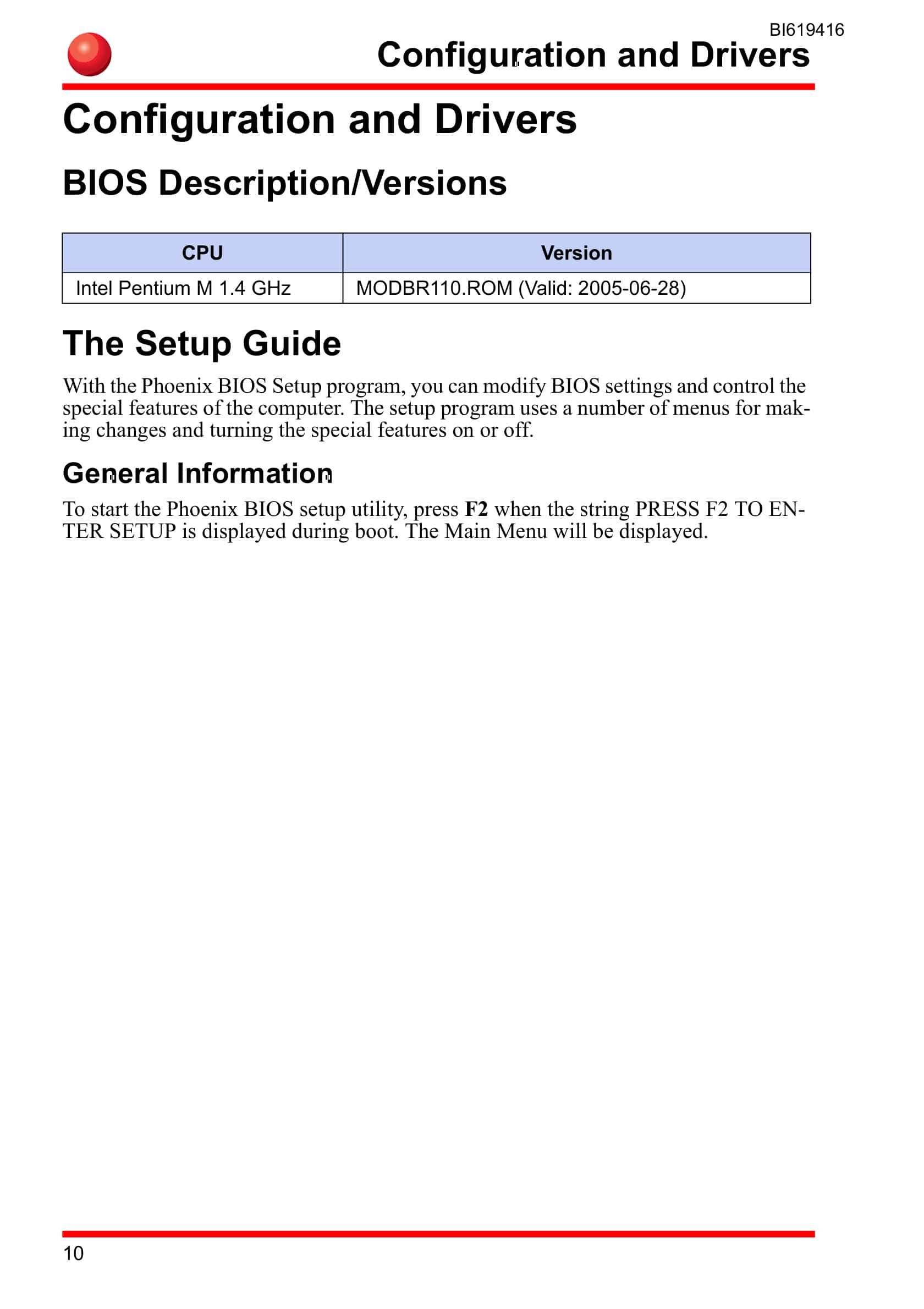
- 1.6.1. BIOS Description/Versions
- 1.6.2. The Setup Guide
- 1.6.3. General Information
- 1.6.4. The Legend Bar
- 1.6.4.1. BIOS Update with Phoenix Phlash
- 1.6.4.1.1. Make a bootable floppy that contains following files Phlash.exe, platform.bin, MODBR110.ROM
- 1.6.4.1.2. Boot up the computer with a USB floppy (See Boot/Install Options on page 15.)
- 1.6.4.1.3. Type following phlash modbr110.rom
- 1.6.4.2. Hardware description
- 1.6.5. Pentium M 1.4 GHz
- 1.6.6. Touch screen
- 1.6.6.1. Start the setup.exe file.
- 1.6.6.2. Install the software, configured with the PS/2 interface.
- 1.6.6.3. Calibrate the touch screen.
- 1.6.6.4. The mouse pointer will move to the point on the screen where you are touching.
- 1.6.6.5. Open the UPDD Calibrate in the programs menu.
- 1.6.6.6. Touch the point marked on the screen.
- 1.6.6.7. Boot/Install Options
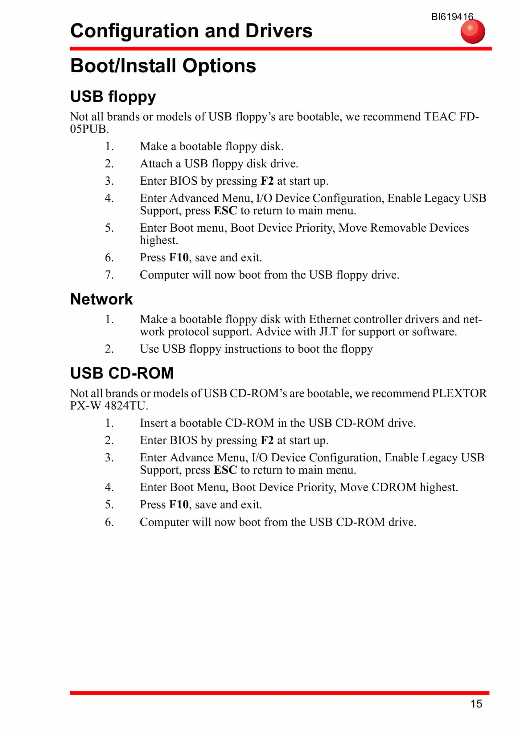
- 1.6.7. USB floppy
- 1.6.7.1. Make a bootable floppy disk.
- 1.6.7.2. Attach a USB floppy disk drive.
- 1.6.7.3. Enter BIOS by pressing F2 at start up.
- 1.6.7.4. Enter Advanced Menu, I/O Device Configuration, Enable Legacy USB Support, press ESC to return to main menu.
- 1.6.7.5. Enter Boot menu, Boot Device Priority, Move Removable Devices highest.
- 1.6.7.6. Press F10, save and exit.
- 1.6.7.7. Computer will now boot from the USB floppy drive.
- 1.6.8. Network
- 1.6.8.1. Make a bootable floppy disk with Ethernet controller drivers and network protocol support. Advice with JLT for support or software.
- 1.6.8.2. Use USB floppy instructions to boot the floppy
- 1.6.9. USB CD-ROM
- 1.6.9.1. Insert a bootable CD-ROM in the USB CD-ROM drive.
- 1.6.9.2. Enter BIOS by pressing F2 at start up.
- 1.6.9.3. Enter Advance Menu, I/O Device Configuration, Enable Legacy USB Support, press ESC to return to main menu.
- 1.6.9.4. Enter Boot Menu, Boot Device Priority, Move CDROM highest.
- 1.6.9.5. Press F10, save and exit.
- 1.6.9.6. Computer will now boot from the USB CD-ROM drive.
- 1.6.10. USB Flash memories
- 1.6.10.1. Insert a bootable USB FLASH MEMORY drive.
- 1.6.10.2. Enter BIOS by pressing F2 at start up.
- 1.6.10.3. Enter Advanced Menu, I/O Device Configuration, Enable Legacy USB Support, press ESC to return to main menu.
- 1.6.10.4. Enter Boot menu, Boot Device Priority, Move Hard Drive highest.
- 1.6.10.5. Enter Hard Drive sub menu and move the Flash memory highest.
- 1.6.10.6. Press F10, save and exit.
- 1.6.10.7. Computer will now boot from the USB Flash memory.
- 1.6.10.8. Secure sound amplifier connection
- 1.6.10.8.1. Various frequency noise when no sound is active.
- 1.6.10.8.2. Noise changes when you touch the computer or computer touch screen.
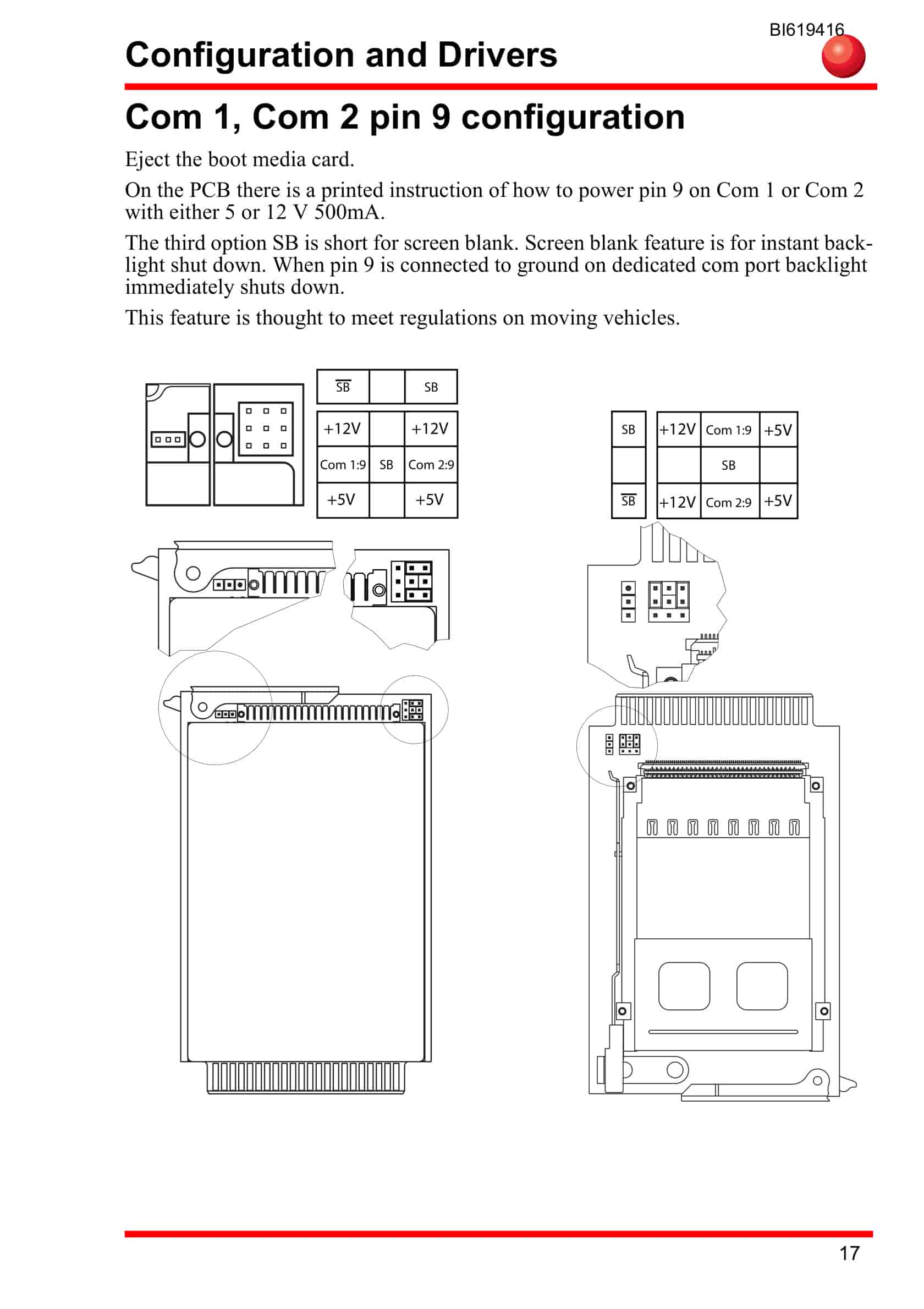
- 1.6.10.9. Com 1, Com 2 pin 9 configuration
- 1.6.10.10. Firmware for LCD timing
- 1.6.11. JILI firmware EEPROM
- 1.6.12. How to program JILI firmware
- 1.6.12.1. Make a bootable floppy with these files jilieep.exe, and paid5.jcf.
- 1.6.12.2. Boot the computer with an USB floppy (see Boot/Install Options on page 15.).
- 1.6.12.3. Type jilieep /write paid5.jcf
- 1.6.12.4. Reboot the computer.
- 1.7. Interface specification
- 1.7.1. Power cable
- 1.7.2. Switch buttons
- 1.8. Technical specification
- 1.9. Physical dimensions
Related products
-
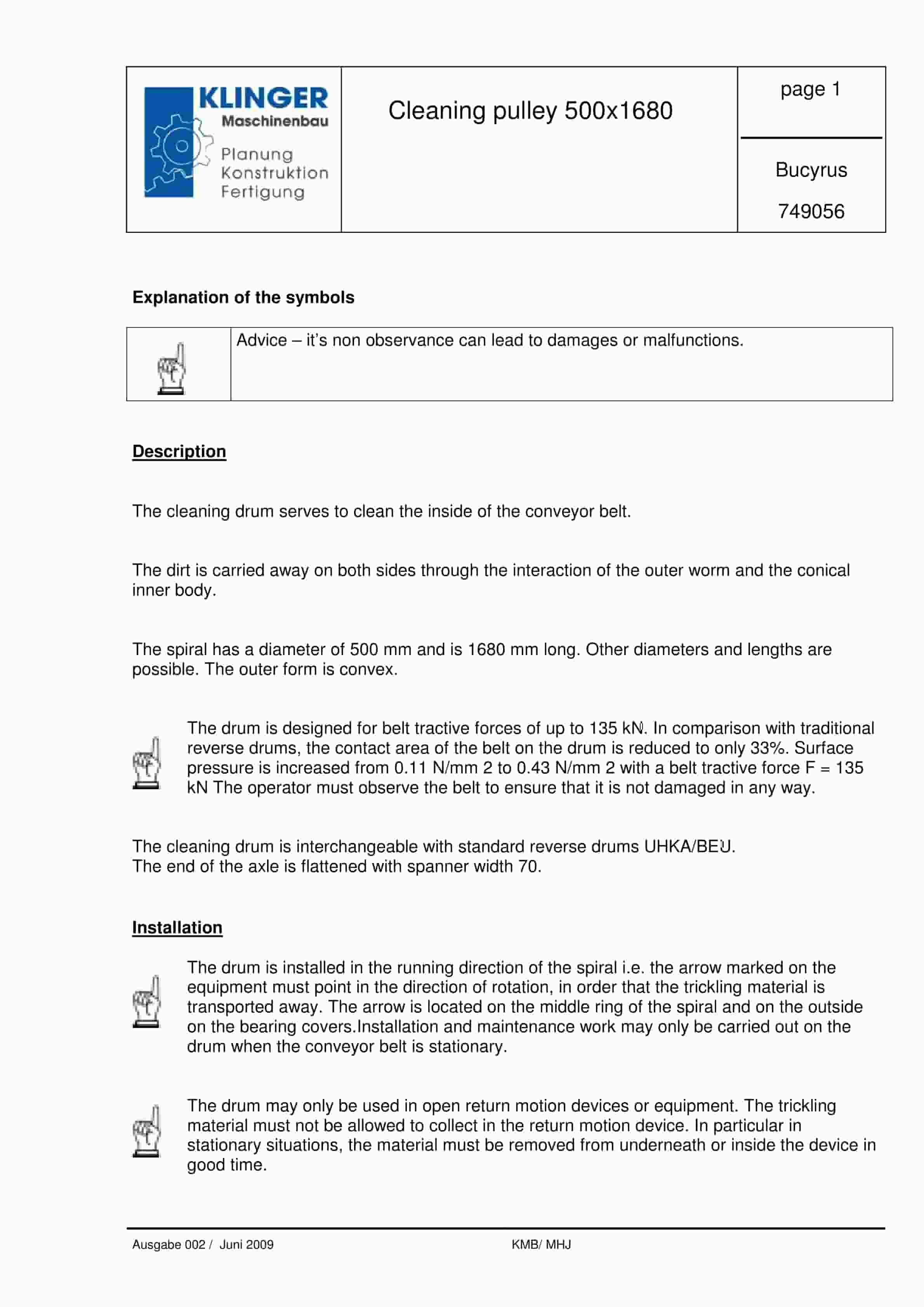
Bucyrus Cleaning Pulley 500 x 1680 Service Parts List 749056
$30.00 Add to cart -
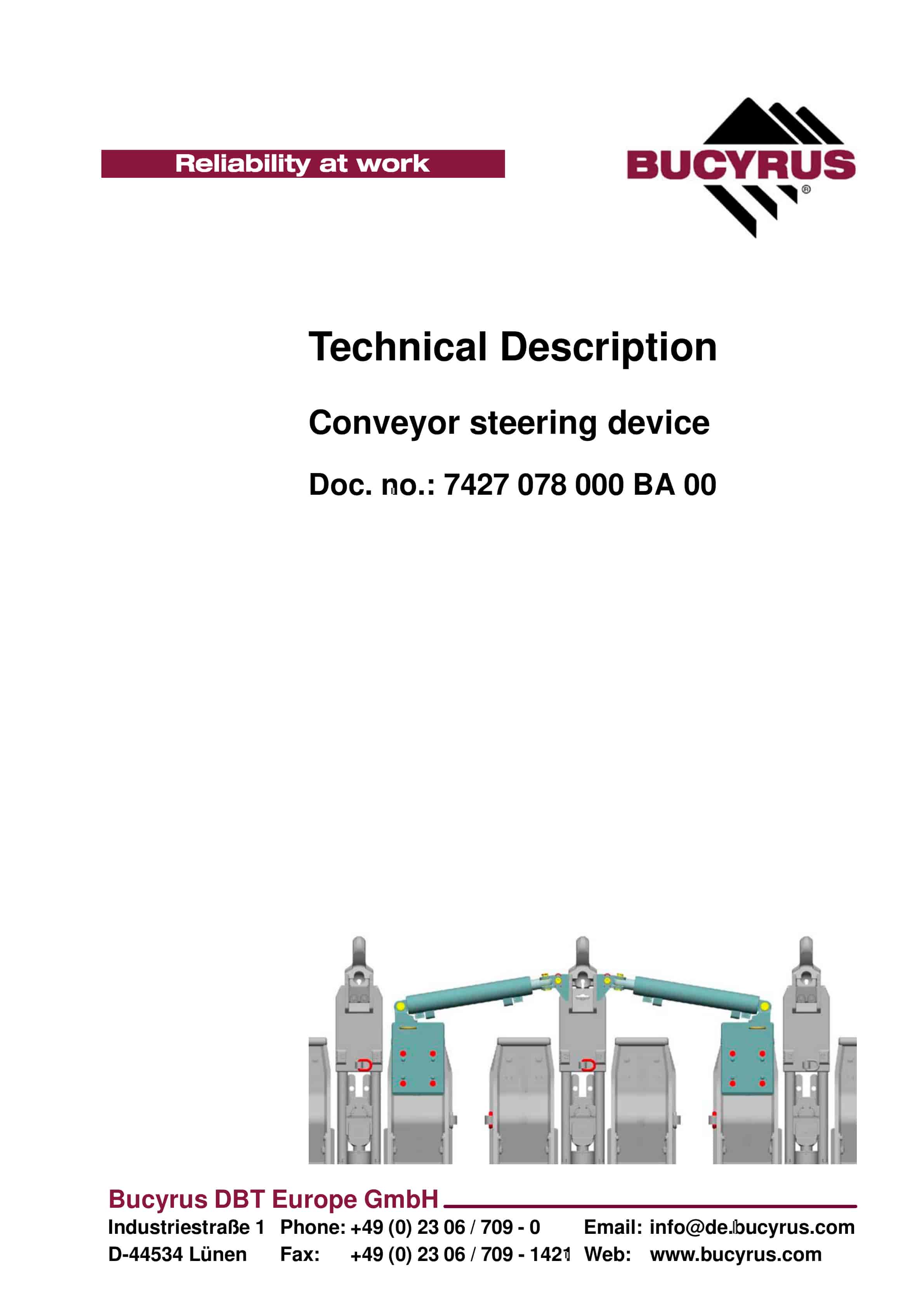
Bucyrus Conveyor Steering Device Technical Description 7427 078 000 BA 00
$30.00 Add to cart -
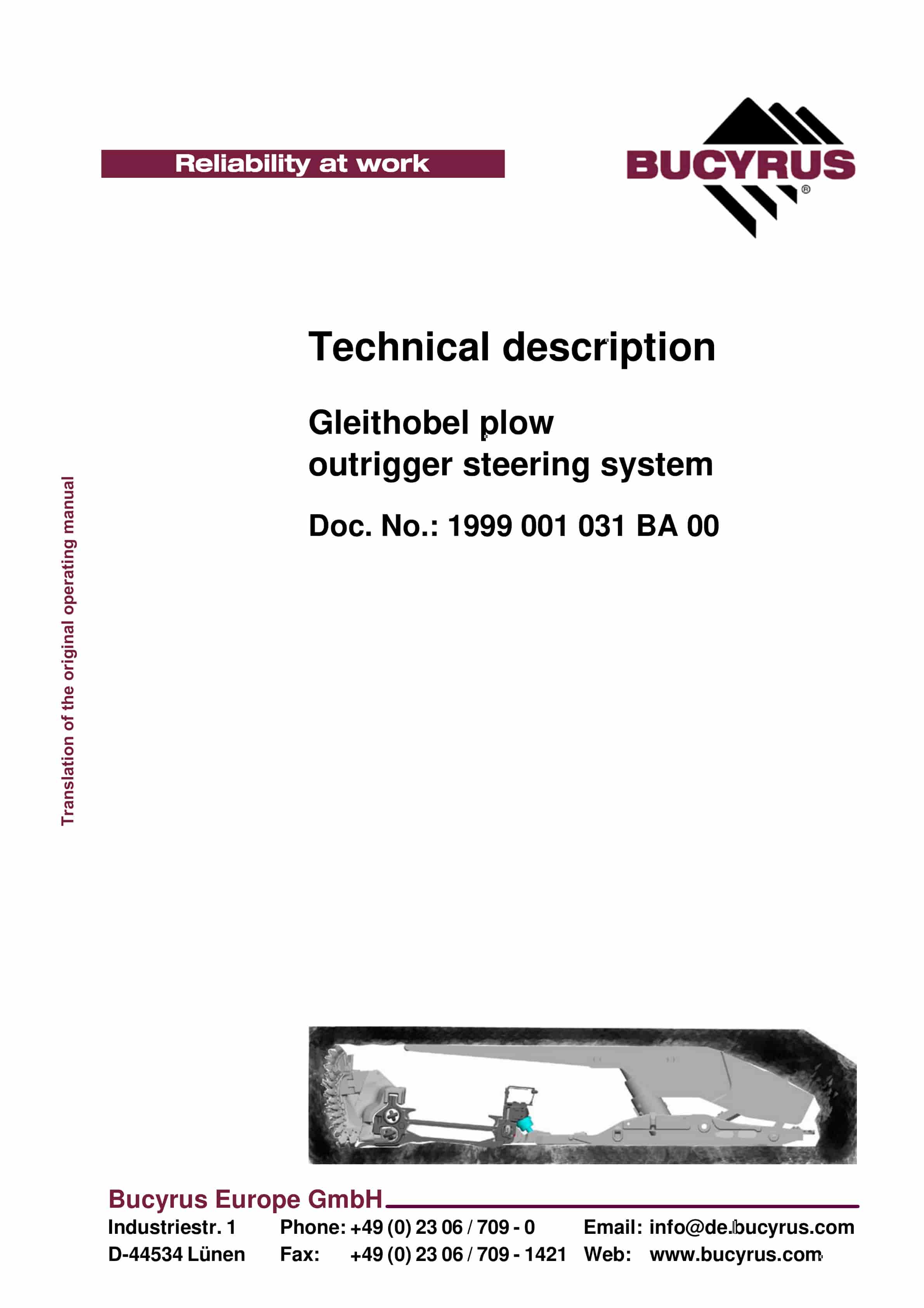
Bucyrus Gleithobel Plow Outrigger Steering System Technical Description 1999 001 031 BA 00
$30.00 Add to cart -
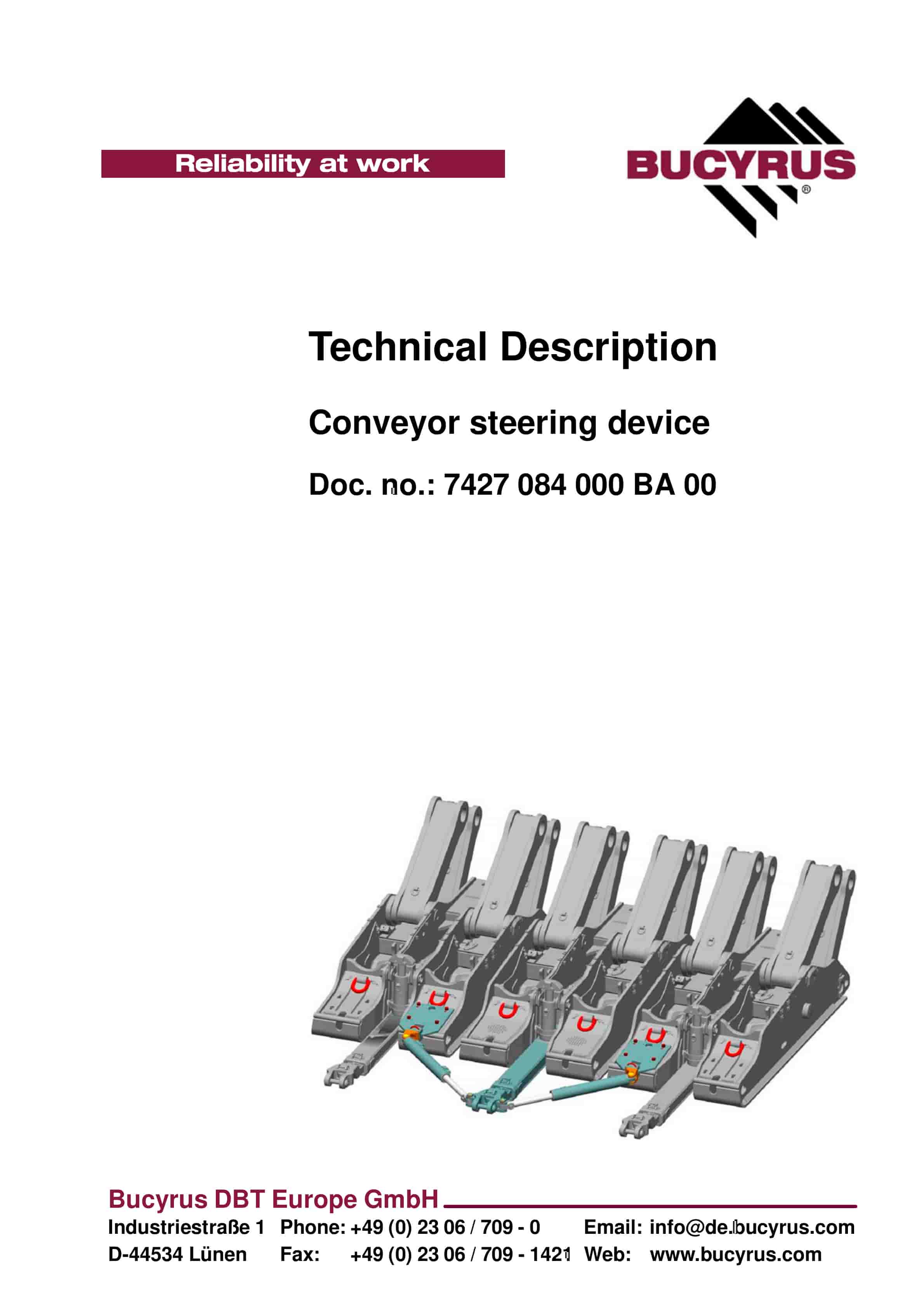
Bucyrus Conveyor Steering Device Technical Description 7427 084 000 BA 00
$30.00 Add to cart -
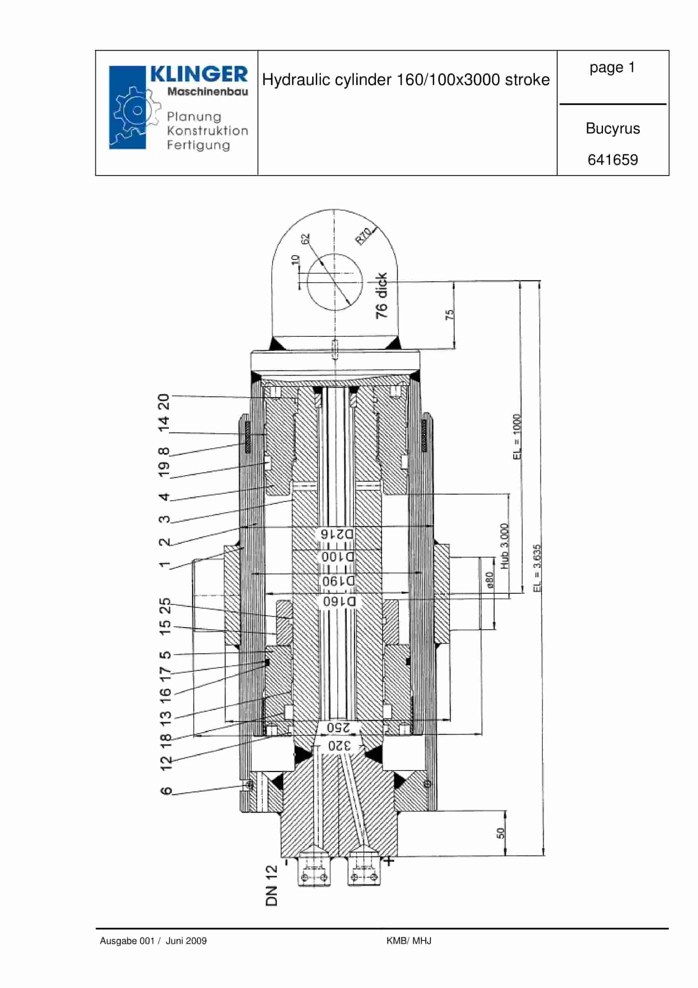
Bucyrus Hydraulic Cylinder 160-100 x 3000 Stroke Service Parts List 641659
$30.00 Add to cart


