

Bucyrus Oaky North Shield Maintenance Procedures Technical Manual BI620086
$30.00
- Type Of Manual: Technical Manual
- Manual ID: BI620086
- Number of Pages: 45
- Size: 1.5MB
- Format: PDF
Product details
-
Model List:
- Oaky North Shield Maintenance Procedures
- 1. M01325.pdf
- 1.1. General Safety
- 1.2. Isolation Procedures
- 1.3. Procedures
- 1.4. Hydraulic Hose Replacement
- 1.5. Confirm Safe to Start. Confirm with the section official th
- 1.6. Electrical Isolation. Push in the lockout button on the sup
- 1.7. Hydraulic Isolation. Isolate the support from the hydraulic
- 1.8. Relieve Hydraulic Pressure. Dissipate pressure by operating
- 1.9. Remove Worn Hose. Remove staple lock and pull hose from fit
- 1.10. Fit New Hose. Fit new hose and replace staple lock pins. E
- 1.11. Remove Hydraulic and Electrical Isolation. Slowly open the
- 1.12. Test Hose Function. Operate the relevant function to test t
- 1.13. Water Hose Replacement
- 1.14. Confirm Safe to Start. Confirm with the section official th
- 1.15. Electrical Isolation. Push in the lockout button on the sup
- 1.16. Isolation of Water Supply. Isolate the support from the wat
- 1.17. Relieve Hydraulic Pressure. Dissipate pressure by operating
- 1.18. Remove Worn Hose. Remove staple lock and pull hose from fit
- 1.19. Fit New Hose. Fit new hose and replace staple lock pins. E
- 1.20. Remove Hydraulic and Electrical Isolation. Slowly open the
- 1.21. Test Hose Function. Operate the water sprays to test the ho
- 1.22. Way Valve Replacement
- 1.23. Confirm Safe to Start. Confirm with the section official th
- 1.24. Electrical Isolation. Push in the lockout button on the sup
- 1.25. Hydraulic Isolation. Isolate the support from the hydraulic
- 1.26. Relieve Hydraulic Pressure. Dissipate pressure by operating
- 1.27. Remove 3/2 Way Valve Cap. Unscrew the 3/2 Way valve cap and
- 1.28. Remove 3/2 Way Valve Capsule. Screw the valve pulling tool
- 1.29. Install Replacement Valve Capsule. Inspect the port for deb
- 1.30. High flow cap 80Nm
- 1.31. Low flow cap 50Nm
- 1.32. Remove Hydraulic and Electrical Isolation. Slowly open the
- 1.33. Test for Correct Function. Operate the relevant hydraulic f
- 1.34. Double Solenoid Pilot Valve
- 1.35. Confirm Safe to Start. Confirm with the section official th
- 1.36. Electrical Isolation. Push in the lockout button on the sup
- 1.37. Hydraulic Isolation. Isolate the support from the hydraulic
- 1.38. Relieve Hydraulic Pressure. Dissipate pressure by operating
- 1.39. Remove Cable. Unscrew cable from double solenoid pilot valv
- 1.40. Remove Valve. Loosen the locating Allen keys securing the d
- 1.41. Replace Valve. Install the replacement valve ensuring O-rin
- 1.42. Remove Hydraulic and Electrical Isolation. Slowly open the
- 1.43. Test Valve Function. Operate the relevant hydraulic functio
- 1.44. Control Block Filter Replacement
- 1.45. Confirm Safe to Start. Confirm with the section official th
- 1.46. Electrical Isolation. Push in the lockout button on the sup
- 1.47. Hydraulic Isolation. Isolate the support from the hydraulic
- 1.48. Relieve Hydraulic Pressure. Dissipate pressure by operating
- 1.49. Access Control Block. The control block assembly has to be
- 1.50. Remove Filter. Unscrew filter to remove from control block.
- 1.51. Replace Filter. Install the replacement or cleaned filter,
- 1.52. Replace Control Blocks. Replace control blocks if moved to
- 1.53. Remove Hydraulic and Electrical Isolation. Slowly open the
- 1.54. Check Control Block Function. Operate the relevant hydrauli
- 1.55. Advancing Cylinder Yield Valve Replacement
- 1.56. Confirm Safe to Start. Confirm with the section official th
- 1.57. Hydraulic Isolation. Isolate the support from the hydraulic
- 1.58. Depressurise Ring Side of Advancing Cylinder. Operate the s
- 1.59. Electrical Isolation. Push in the lockout button on the sup
- 1.60. Remove Yield Valve. Remove the staple retaining the yield v
- 1.61. Replace Yield Valve. Install the replacement valve and repl
- 1.62. Remove Hydraulic and Electrical Isolation. Slowly open the
- 1.63. Test for Correct Function. Operate the advancing cylinder t
- 1.64. Leg Pressure Gauge Replacement
- 1.65. Confirm Safe to Start. Confirm with the section official th
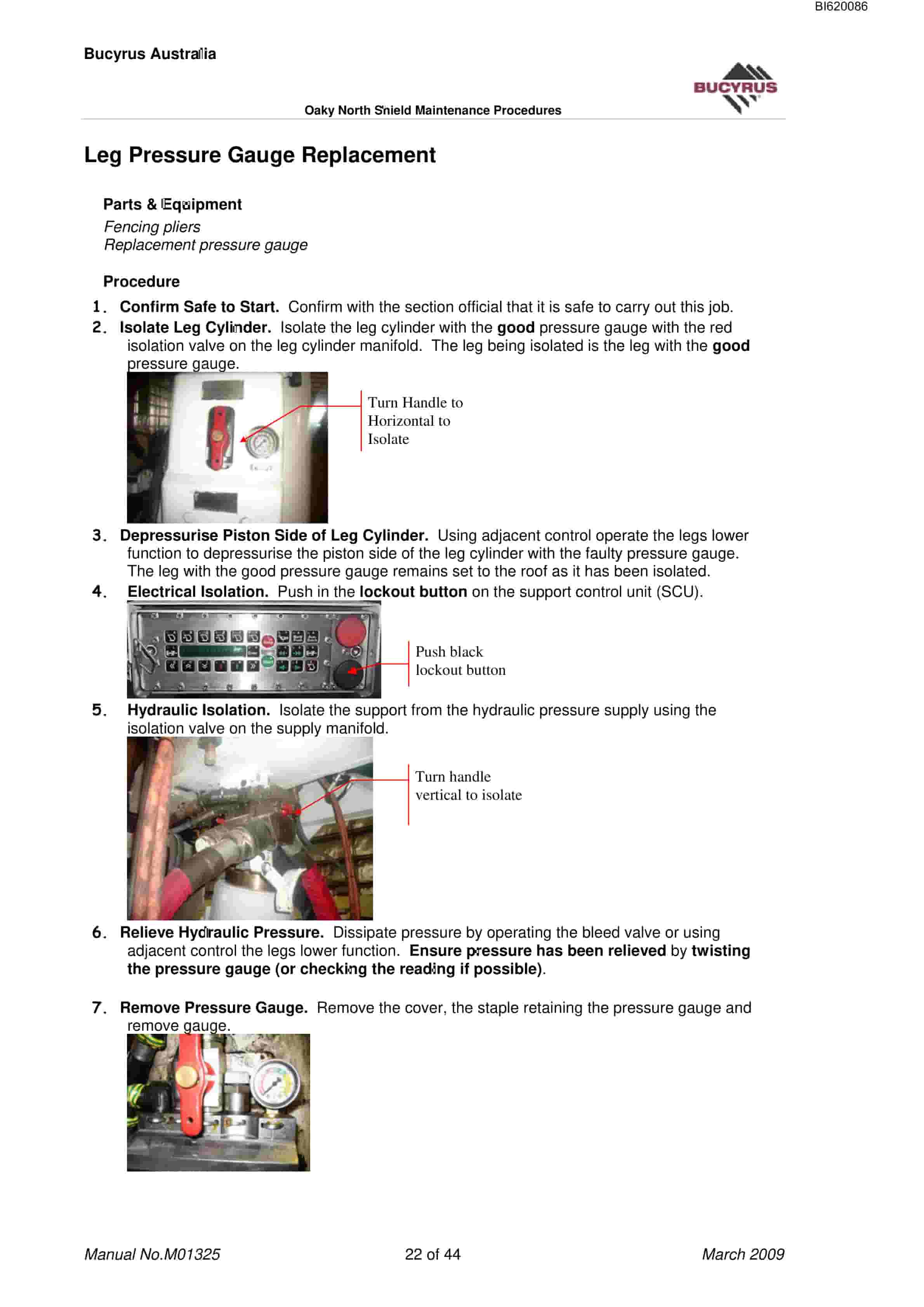
- 1.66. Isolate Leg Cylinder. Isolate the leg cylinder with the goo
- 1.67. Depressurise Piston Side of Leg Cylinder. Using adjacent co
- 1.68. Electrical Isolation. Push in the lockout button on the sup
- 1.69. Hydraulic Isolation. Isolate the support from the hydraulic
- 1.70. Relieve Hydraulic Pressure. Dissipate pressure by operating
- 1.71. Remove Pressure Gauge. Remove the cover, the staple retaini
- 1.72. Replace Pressure Gauge. Install the replacement valve and r
- 1.73. Remove Leg Cylinder Isolation. Open the leg cylinder isolat
- 1.74. Remove Hydraulic and Electrical Isolation. Slowly open the
- 1.75. Test for Correct Function. Set the legs to the roof using a
- 1.76. Leg Cylinder Yield Valve Replacement
- 1.77. Confirm Safe to Start. Confirm with the section official th
- 1.78. Isolate Leg Cylinder. Isolate the leg cylinder with the yie
- 1.79. Relieve Hydraulic Pressure. Dissipate pressure by operating
- 1.80. Electrical Isolation. Push in the lockout button on the sup
- 1.81. Hydraulic Isolation. Isolate the support from the hydraulic
- 1.82. Remove Yield Valve. Remove the staple retaining the yield v
- 1.83. Replace Yield Valve. Install the replacement valve and rene
- 1.84. Remove Leg Cylinder Isolation. Open the leg cylinder isolat
- 1.85. Remove Hydraulic and Electrical Isolation. Slowly open the
- 1.86. Test for Correct Function. Set the legs to the roof and che
- 1.87. Pressure Sensor Replacement
- 1.88. Confirm Safe to Start. Confirm with the section official th
- 1.89. Isolate Leg Cylinder. Isolate the leg cylinder with the pre
- 1.90. Relieve Hydraulic Pressure. Dissipate pressure by operating
- 1.91. Electrical Isolation. Push in the lockout button on the sup
- 1.92. Hydraulic Isolation. Isolate the support from the hydraulic
- 1.93. Remove pressure sensor. Remove the staple retaining the pre
- 1.94. Replace sensor. Connect the cable and Install the replacemen
- 1.95. Remove Leg Cylinder Isolation. Open the leg cylinder isolat
- 1.96. Remove Hydraulic and Electrical Isolation. Slowly open the
- 1.97. Test for Correct Function. Set the legs to the roof and che
- 1.98. Advancing Cylinder Replacement
- 1.99. Confirm Safe to Start. Confirm with the section official th
- 1.100. Preparation.
- 1.101. Disconnect the relay bar from the pan
- 1.102. AFC should be advanced and support left back(advancing cylin
- 1.103. Supports to left and right should be left back to provide cl
- 1.104. Transport replacement cylinder to site.
- 1.105. Electrical Isolation. Push in the lockout button on the sup
- 1.106. Hydraulic Isolation. Isolate the support from the 350 bar p
- 1.107. Depressurise Ring Side of Advancing Cylinder. Use the bleed
- 1.108. Remove Walkway Plate. Tip SCU bracket to rear position and
- 1.109. Disconnect Cables Hoses. Disconnect the SKK24 cable from
- 1.110. Disconnect Hoses. Twist hoses to ensure pressure has been d
- 1.111. Disconnect Remove Baselift Cylinder. Disconnect and remov
- 1.112. Remove Front Locking Bracket. Remove staples and pins and r
- 1.113. Pull Relay Bar Assembly to Face. Attach a chain block to a
- 1.114. Remove Rear Locking Pin. Remove the retaining clip and lock
- 1.115. Lift Remove Advancing Cylinder. Attach a chain block and
- 1.116. Install Replacement Cylinder. Reverse the procedure to mano
- 1.117. Locate Cylinder in Rear Slots of Relay Bar. Using the chain
- 1.118. Replace Rear Locking Pins. Replace the rear locking pins in
- 1.119. Attach to Front Mounting Clevis. Push relay bar assembly to
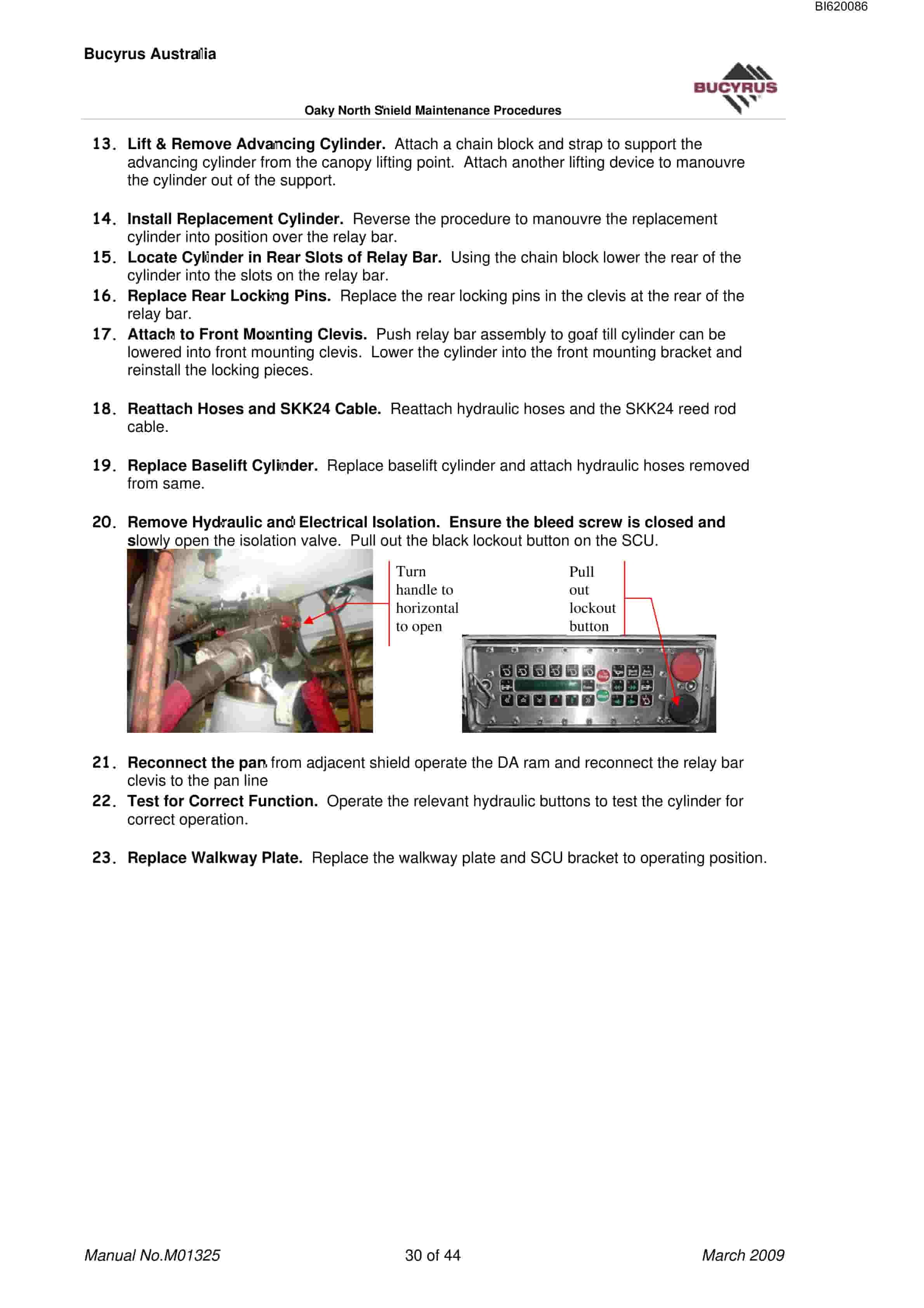
- 1.120. Reattach Hoses and SKK24 Cable. Reattach hydraulic hoses an
- 1.121. Replace Baselift Cylinder. Replace baselift cylinder and at
- 1.122. Remove Hydraulic and Electrical Isolation. Ensure the bleed
- 1.123. Reconnect the pan from adjacent shield operate the DA ram an
- 1.124. Test for Correct Function. Operate the relevant hydraulic b
- 1.125. Replace Walkway Plate. Replace the walkway plate and SCU br
- 1.126. Leg Cylinder Replacement
- 1.127. Confirm Safe to Start. Confirm with the section official th
- 1.128. Lower Shield to Working Height. Using adjacent control lowe
- 1.129. Electrical Isolation. Push in the lockout button on the sup
- 1.130. Isolate Leg Cylinder. Isolate the good leg cylinder (ie. th
- 1.131. Hook up Chain Block..Hook up a chain block from the lifting
- 1.132. Remove Upper Cylinder Retaining Pins..Remove the two retaini
- 1.133. Lower Leg to Fully Closed. Using the manual control buttons
- 1.134. Hydraulic Isolation. Isolate the support from the hydraulic
- 1.135. Depressurise Piston Side of Leg Cylinder. Press the legs lo
- 1.136. Remove Base Leg Retainers. Lift walkway plate to access ret
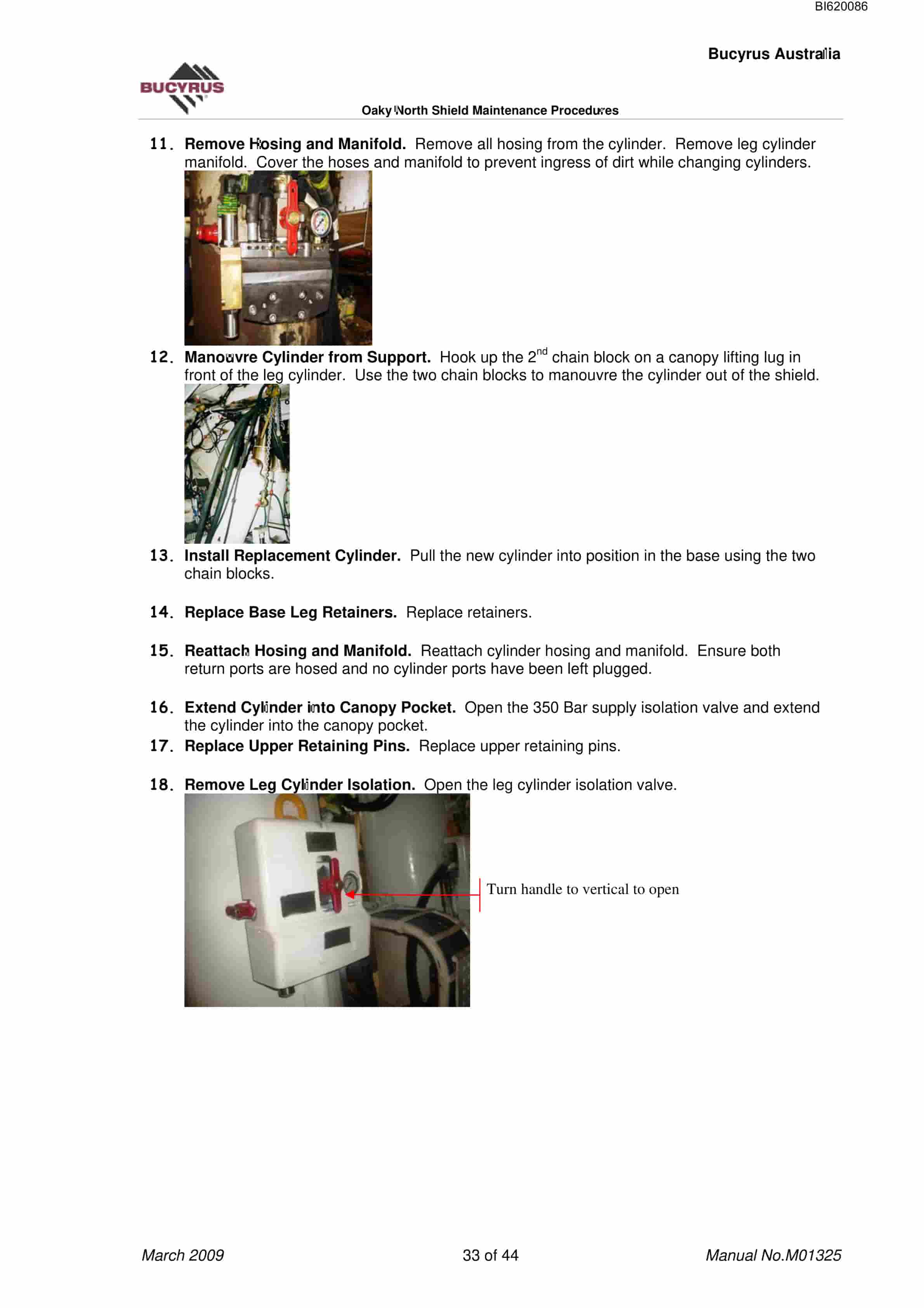
- 1.137. Remove Hosing and Manifold. Remove all hosing from the cyli
- 1.138. Manouvre Cylinder from Support. Hook up the 2nd chain block
- 1.139. Install Replacement Cylinder. Pull the new cylinder into po
- 1.140. Replace Base Leg Retainers. Replace retainers.
- 1.141. Reattach Hosing and Manifold. Reattach cylinder hosing and
- 1.142. Extend Cylinder into Canopy Pocket. Open the 350 Bar supply
- 1.143. Replace Upper Retaining Pins. Replace upper retaining pins.
- 1.144. Remove Leg Cylinder Isolation. Open the leg cylinder isolat
- 1.145. Remove Hydraulic and Electrical Isolation. Slowly open the
- 1.146. Set Support to Roof Check Cylinder Function. Raise the su
- 1.147. Stabilising Cylinder Replacement
- 1.148. Confirm Safe to Start. Confirm with the section official th
- 1.149. Prepare for Cylinder Removal. Ensure both legs are operatin
- 1.150. Hydraulic Isolation. Isolate the support from the hydraulic
- 1.151. Check Circuit is Depressurised. Operate the cylinder using
- 1.152. Electrical Isolation. Push in the lockout button on the sup
- 1.153. operate both the bleed screws at the POCV
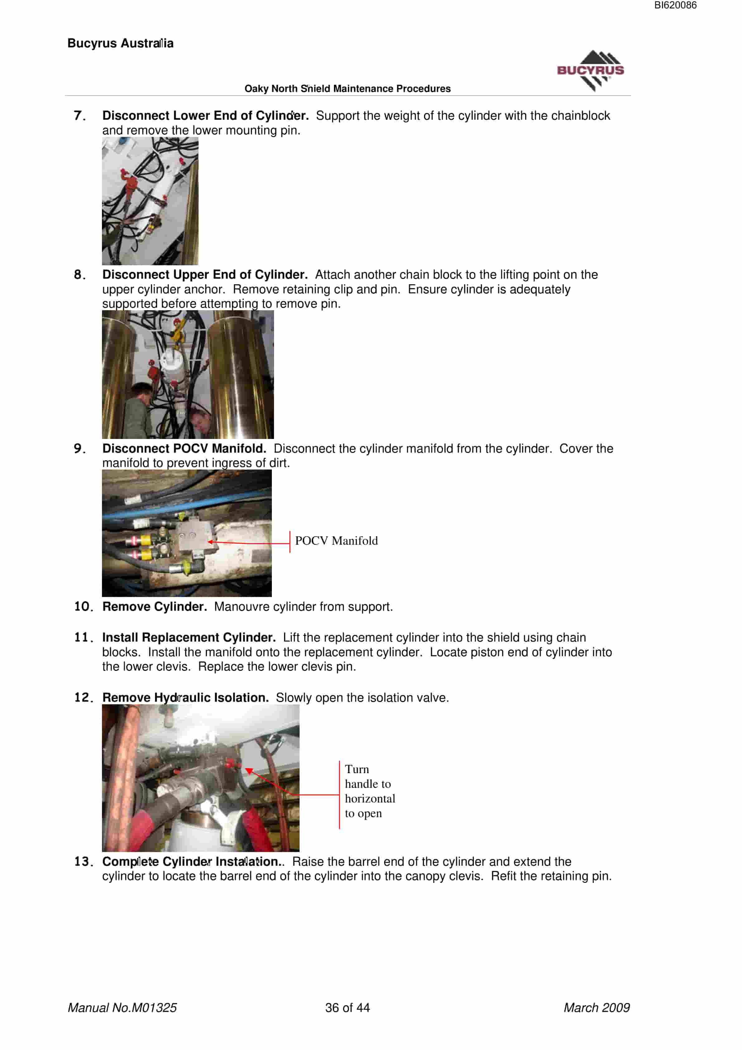
- 1.154. Disconnect Lower End of Cylinder. Support the weight of the
- 1.155. Disconnect Upper End of Cylinder. Attach another chain bloc
- 1.156. Disconnect POCV Manifold. Disconnect the cylinder manifold
- 1.157. Remove Cylinder. Manouvre cylinder from support.
- 1.158. Install Replacement Cylinder. Lift the replacement cylinder
- 1.159. Remove Hydraulic Isolation. Slowly open the isolation valve
- 1.160. Complete Cylinder Instalation.. Raise the barrel end of the
- 1.161. Remove Electrical Isolation. Pull out the black lockout but
- 1.162. Test the Cylinder Function. Tilt canopy up and down to chec
- 1.163. Flipper and Sprag Cylinder Replacement
- 1.164. Confirm Safe to Start. Confirm with the section official th
- 1.165. Prepare for Cylinder Removal. Either lower the support so t
- 1.166. Hydraulic Isolation. Isolate the support from the hydraulic
- 1.167. Check Circuit is Depressurised. Operate the flipper and fli
- 1.168. Electrical Isolation. Push in the lockout button on the sup
- 1.169. Disconnect Hoses. Disconnect hoses from cylinder.to be chan
- 1.170. Remove Cylinder. The sprag cylinder can be removed easily b
- 1.171. Replace Cylinder. Install replacement cylinder and refit re
- 1.172. Reconnect Hoses. Reconnect the hoses removed earlier fittin
- 1.173. Remove Hydraulic and Electrical Isolation. Slowly open the
- 1.174. Test Cylinder Function. Operate the flipper / flipper exten
- 1.175. Side Seal Cylinder Replacement
- 1.176. Confirm Safe to Start. Confirm with the section official th
- 1.177. Prepare for Cylinder Removal. Set the side shield so it is
- 1.178. Electrical Isolation. Push in the lockout button on the sup
- 1.179. Remove Tailgate Side Cylinder Retaining Pins. Remove staple
- 1.180. Hydraulic Isolation. Isolate the support from the hydraulic
- 1.181. Depressurise Circuit. Operate the manual buttons for the si
- 1.182. Remove Cover Plate. Remove the cover plate from side shield
- 1.183. Disconnect Hydraulics. Disconnect all hoses from the cylind
- 1.184. Remove Maingate Side Cylinder Retaining Pin. Remove staple
- 1.185. Remove Cylinder. Pull cylinder and rod from support until u
- 1.186. Replace Cylinder. Connect replacement cylinder onto knuckle
- 1.187. Reconnect Hoses. Reconnect the hoses removed earlier and re
- 1.188. Remove Hydraulic and Electrical Isolation. Slowly open the
- 1.189. Test Cylinder Function. Operate the side seal to check for
- 1.190. Support Control Unit (SCU) Replacement
- 1.191. Confirm Safe to Start. Confirm with the section official th
- 1.192. Electrical Isolation. Push in the lockout button on the sup
- 1.193. Remove Mounting Bolts. Remove the two Allen key bolts at ea
- 1.194. Remove SCU. Pull the SCU off the dowels to remove.
- 1.195. Check New SCU. Check the rear of the SCU for plastic blanki
- 1.196. Replace SCU. Fit the new SCU onto the locating dowels. Ins
- 1.197. Check Program. Check the version numbers of the software in
- 1.198. Check SCU Function. Operate some support functions via the
- 1.199. Power Adaptor Replacement
- 1.200. Confirm Safe to Start. Confirm with the section official th
- 1.201. Electrical Isolation. Push in the lockout button on the sup
- 1.202. Remove Cables. Remove staples and pull cables from sockets
- 1.203. Remove Power Adaptor. Unbolt location bolts and remove powe
- 1.204. Install Replacement Power Adaptor. Install replacement powe
- 1.205. Check SCUs. Pull out the black lockout button and check pow
- 1.206. Solenoid Driver Replacement
- 1.207. Confirm Safe to Start. Confirm with the section official th
- 1.208. Electrical Isolation. Push in the lockout button on the sup
Related products
-
Bucyrus Belt System Spare Parts List 203106
$30.00 Add to cart -
Bucyrus General Data Technical Handbook 2804198
$30.00 Add to cart -

Bucyrus Fundamentals Of Electrical Engineering Technical Handbook 2440049
$30.00 Add to cart -
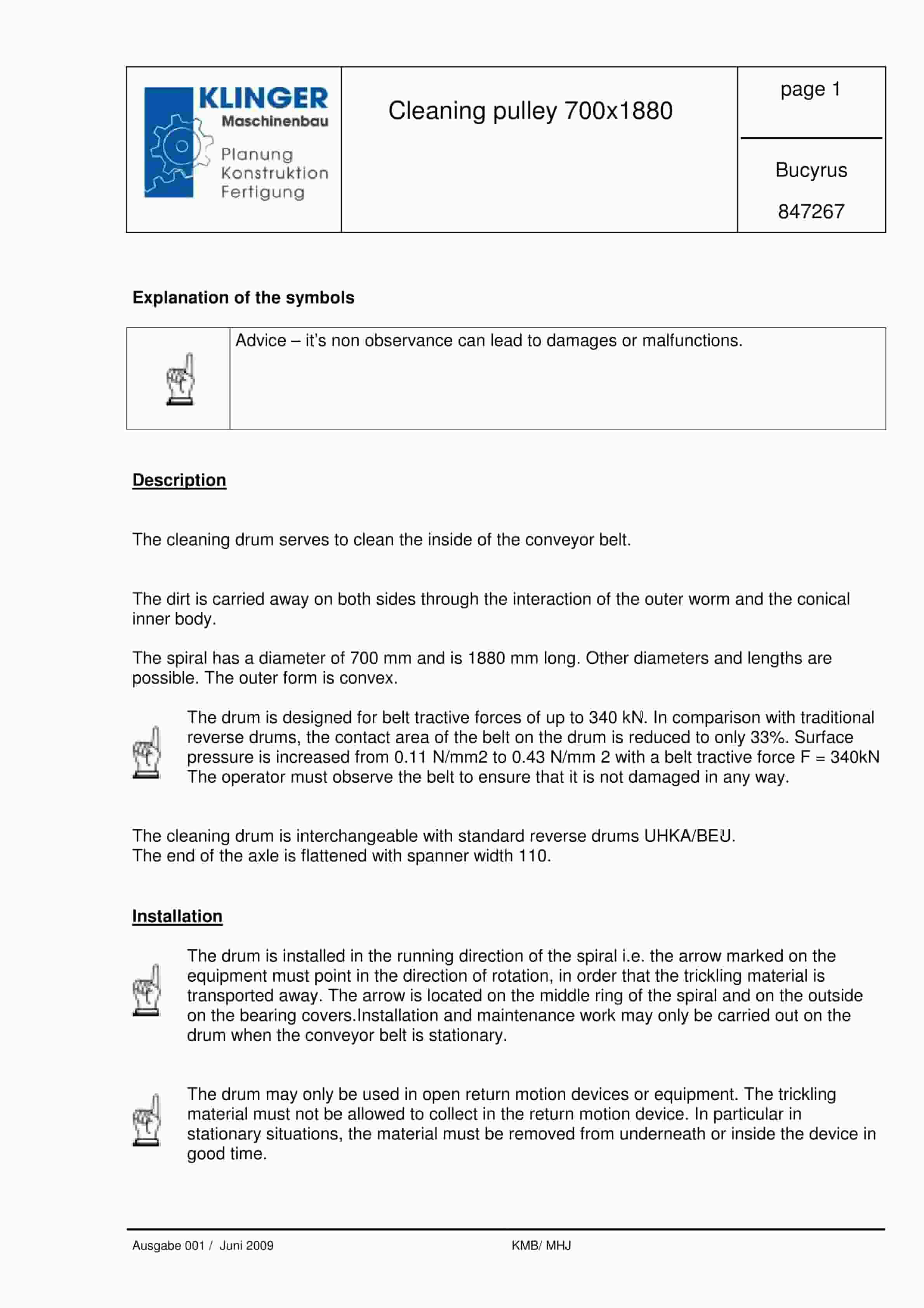
Bucyrus Cleaning Pulley 700 x 1880 Service Parts List 847267
$30.00 Add to cart -
Bucyrus Continuous Miner Spare Parts List 373608
$30.00 Add to cart


