


Bucyrus PanelView Plus Terminals Technical Manual BI619489
$30.00
- Type Of Manual: Technical Manual
- Manual ID: BI619489
- Number of Pages: 249
- Size: 14.3MB
- Format: PDF
Product details
-
Model List:
- PanelView Plus Terminals
- 1. GD12325545_1.pdf
- 1.1. UM001H-EN-P, PanelView Plus Terminals
- 1.2. Important User Information
- 1.3. Summary of Changes
- 1.4. Preface
- 1.4.1. Objectives
- 1.4.2. Intended Audience
- 1.4.3. Parts List
- 1.4.4. Additional Resources
- 1.4.5. Software and Firmware Upgrades
- 1.5. Table of Contents
- 1.6. Overview
- 1.6.1. Chapter Objectives
- 1.6.2. Software Support
- 1.6.3. PanelView Plus 400 and 600 Terminals
- 1.6.3.1. Base-configured Units
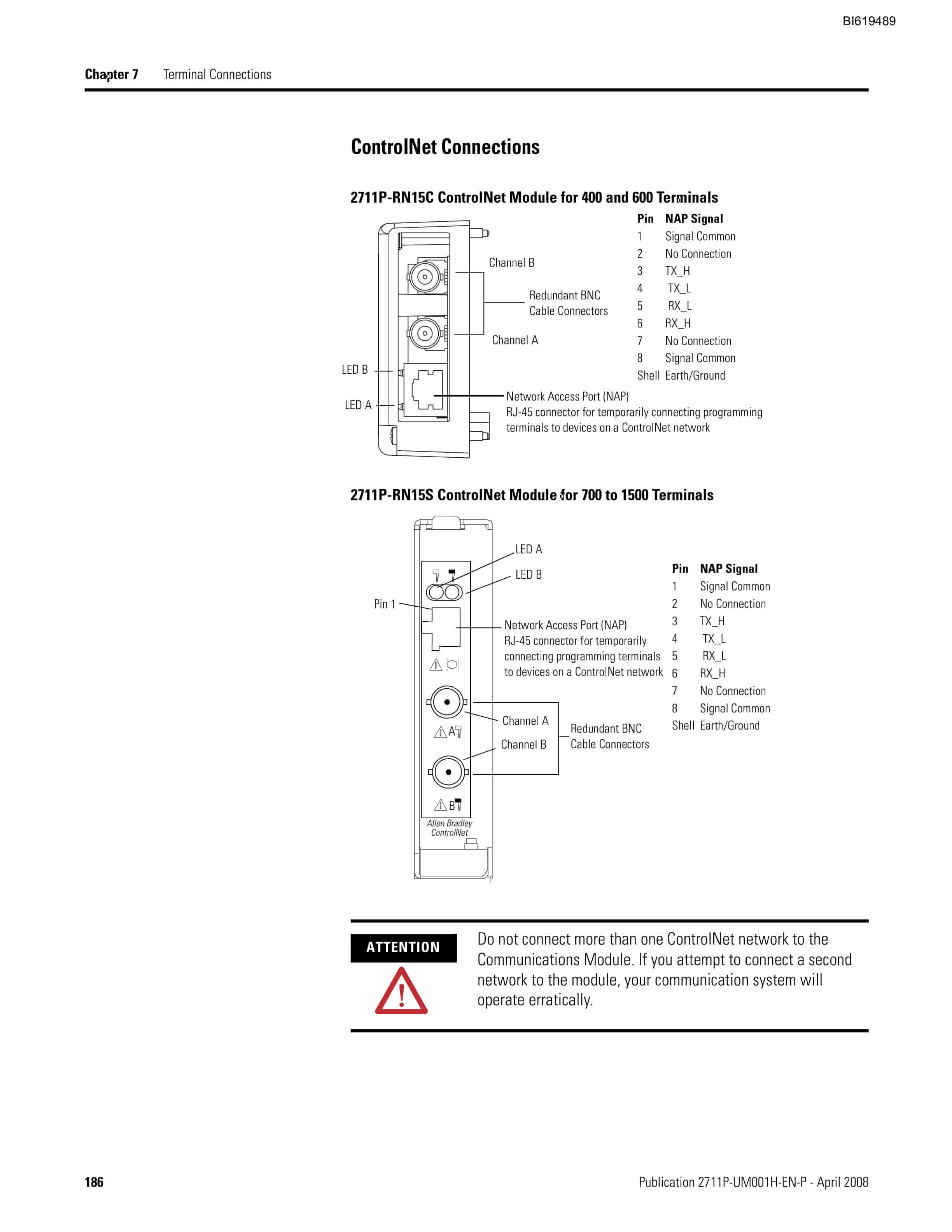
- 1.6.3.2. Communication Modules
- 1.6.3.3. Power Options
- 1.6.3.4. Display and Input Options
- 1.6.4. PanelView Plus 700 to 1500 Terminals
- 1.6.4.1. Modular Components
- 1.6.4.2. Base-configured Unit
- 1.6.4.3. Logic Modules and CompactFlash
- 1.6.4.4. Communication Modules
- 1.6.4.5. Power Options
- 1.6.4.6. Display Modules
- 1.6.5. Catalog Number Configuration
- 1.6.6. PanelView Plus Product Components
- 1.7. Installation
- 1.7.1. Chapter Objectives
- 1.7.2. Hazardous Locations
- 1.7.2.1. USB Ports
- 1.7.3. Environment and Enclosure
- 1.7.4. Outdoor Installation for High-bright Displays
- 1.7.5. Required Tools
- 1.7.6. Clearances
- 1.7.7. Cutout Dimensions
- 1.7.8. Mount the 400 or 600 Terminal in a Panel
- 1.7.8.1. Cut an opening in the panel by using the panel cutout shipped with the terminal.
- 1.7.8.2. If a communication module is ordered separately, attach the module to the base unit before panel installation.
- 1.7.8.3. Make sure the terminal sealing gasket is properly positioned on the terminal.
- 1.7.8.4. Install legend strips before installing the terminal if you are using keypad legend strips on a 600 keypad terminal.
- 1.7.8.5. Place the terminal in the panel cutout.
- 1.7.8.6. Insert all mounting levers into the mounting slots on the terminal.
- 1.7.8.7. When all levers are in place, slide each lever an additional notch or two until you hear a click.
- 1.7.8.8. Rotate each lever in the direction indicated until it is in the final latch position.
- 1.7.9. Mount the 700 to 1500 Terminal in a Panel
- 1.7.9.1. Cut an opening in the panel by using the panel cutout shipped with the terminal.
- 1.7.9.2. Make sure the terminal sealing gasket is properly positioned on the terminal.
- 1.7.9.3. Install the legend strips before installing the terminal if you are using keypad legend strips on keypad terminals.
- 1.7.9.4. Place the terminal in the panel cutout.
- 1.7.9.5. Slide the ends of the mounting clips into the slots on the terminal.
- 1.7.9.6. Tighten the mounting clip screws by hand until the gasket seal contacts the mounting surface uniformly.
- 1.7.9.7. Tighten the mounting clips screws to a torque of 0.901.1 Nm (810 lb.in) by using the specified sequence, making sure not to overtighten.
- 1.7.10. Product Dimensions
- 1.8. Power Connections
- 1.8.1. Chapter Objectives
- 1.8.2. Wiring and Safety Guidelines
- 1.8.3. Remove and Install the Power Terminal Block
- 1.8.3.1. and 600 Terminals
- 1.8.3.2. to 1500 Terminals
- 1.8.4. DC Power Connections
- 1.8.4.1. External Power Supply For Non-insolated DC Terminals
- 1.8.4.2. External Power for 700 to 1500 Isolated DC Terminals (2711P-RxxDx Logic Modules)
- 1.8.4.3. Earth/Ground Connection
- 1.8.4.4. Connect DC Power
- 1.8.5. AC Power Connections
- 1.8.5.1. Protective Earth Connection
- 1.8.5.2. Functional Earth Connection
- 1.8.5.3. Connect AC Power
- 1.8.6. Reset the Terminals
- 1.9. Configuration Mode
- 1.9.1. Chapter Objectives
- 1.9.2. Access Configuration Mode
- 1.9.2.1. Navigation Buttons
- 1.9.2.2. Enter or Edit Data
- 1.9.3. Load an Application
- 1.9.3.1. Select Load Application from the main screen.
- 1.9.3.2. Press the Source button to select the storage location of the application file you want to load.
- 1.9.3.3. Select an .MER file from the list by using the up and down cursor keys.
- 1.9.3.4. Press the Load button to load the selected application.
- 1.9.3.5. Select Yes or No.
- 1.9.4. Run an Application
- 1.9.5. Application Settings
- 1.9.6. Terminal Settings
- 1.9.6.1. Select Terminal Settings from the main screen.
- 1.9.6.2. Highlight an option by using the up and down cursor buttons.
- 1.9.6.3. Press the Enter key to access the highlighted function.
- 1.9.7. Configure Communications
- 1.9.7.1. KEPServer Serial Port IDs
- 1.9.7.2. Configure Communication Properties
- 1.9.7.3. Configure the Controller Address
- 1.9.8. Configure Network Information
- 1.9.8.1. Define a Device Name for the Terminal
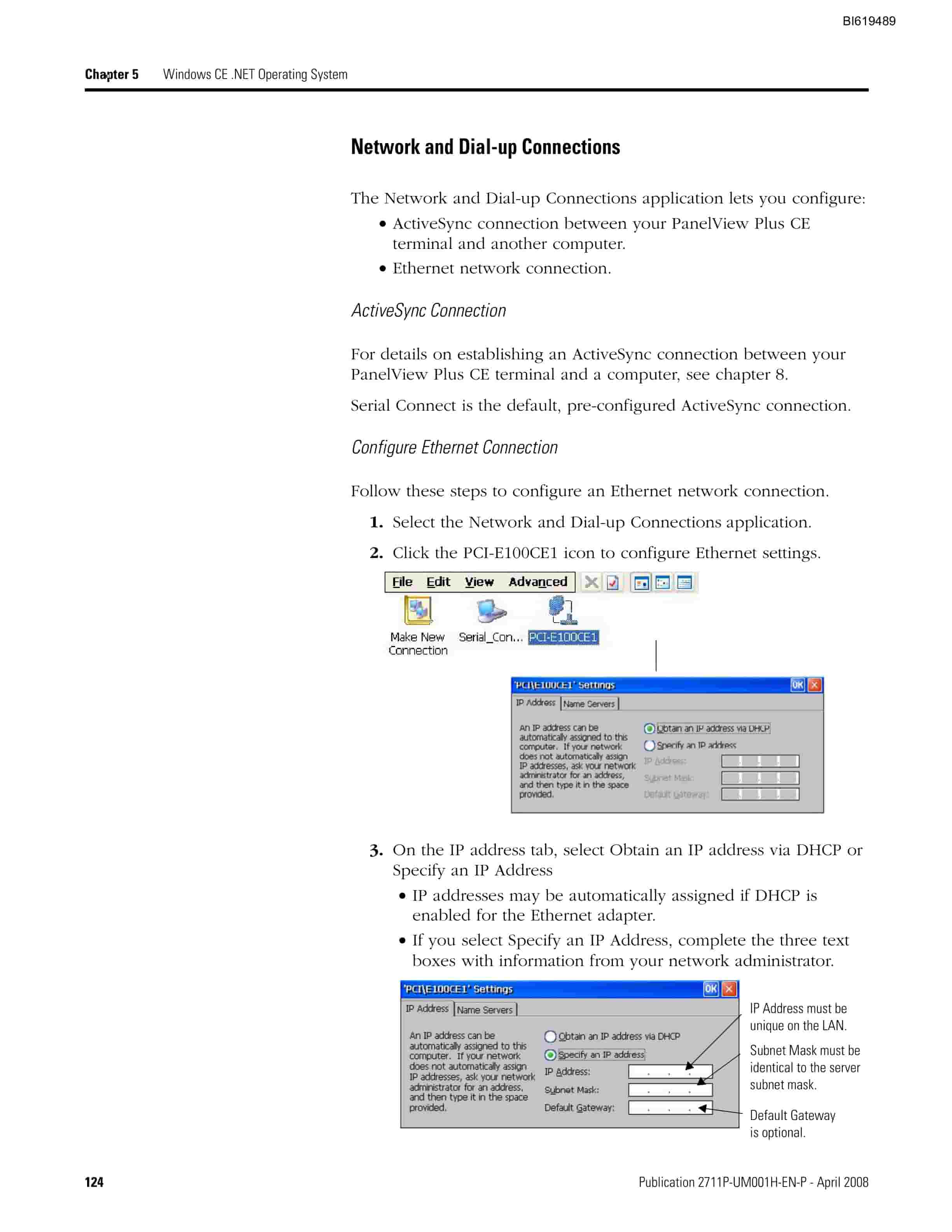
- 1.9.8.2. Define an Ethernet IP Address
- 1.9.8.3. Define Name Server Addresses
- 1.9.8.4. Authorize Terminal to Access Network Resources
- 1.9.9. Configure Diagnostics
- 1.9.9.1. Remote Log Destination
- 1.9.9.2. Message Routing
- 1.9.10. Manage Files on the Terminal
- 1.9.10.1. Delete an Application File or a Font File
- 1.9.10.2. Delete Log Files from Terminal
- 1.9.10.3. Copy an Application File or Font File
- 1.9.11. Modify Display Settings
- 1.9.11.1. View the Display Temperature
- 1.9.11.2. Adjust the Display Contrast
- 1.9.11.3. Adjust the Display Intensity
- 1.9.11.4. Configure the Screen Saver
- 1.9.11.5. Enable or Disable the Screen Cursor
- 1.9.12. Font Linking
- 1.9.13. Configure Keypad, Keyboard, or Mouse
- 1.9.13.1. Configure Keyboard Settings
- 1.9.13.2. Configure Keypad Settings for the Terminal
- 1.9.13.3. Configure the Sensitivity of the Mouse
- 1.9.14. Configure the Touch Screen
- 1.9.14.1. Calibrate the Touch-screen
- 1.9.14.2. Enable or Disable the Cursor on Touch Screens
- 1.9.14.3. Set the Double-tap Sensitivity
- 1.9.15. Configure Print Options
- 1.9.15.1. Select a Terminal Settings>Networks and Communications>Print Setup> option.
- 1.9.15.2. Update properties by selecting the appropriate button and changing the value, if necessary.
- 1.9.15.3. Press the Advanced button to access additional settings.
- 1.9.15.4. Press OK when done.
- 1.9.15.5. Press OK to return to Terminal Settings.
- 1.9.16. Configure Startup Options
- 1.9.16.1. Select Terminal Settings>Startup Options>FactoryTalk View ME Station Startup.
- 1.9.16.2. Press the On Startup button until Do not start FactoryTalk View ME is selected.
- 1.9.16.3. Press OK.
- 1.9.16.4. Enter Configuration Mode on Startup
- 1.9.16.5. Run the Loaded Application on Startup
- 1.9.16.6. Startup Shortcuts for PanelView Plus CE Devices
- 1.9.17. Configure Startup Tests
- 1.9.17.1. Select Tests to Run on Startup
- 1.9.17.2. Configure Startup Test Settings
- 1.9.18. View and Clear the System Event Log
- 1.9.18.1. Select Terminal Settings>System Event Log.
- 1.9.18.2. Select an event and then press the More Details button to display system event log details for that event.
- 1.9.18.3. Press the Clear All button to clear all system event logs.
- 1.9.18.4. Press OK.
- 1.9.19. Display Terminal Information
- 1.9.19.1. Select Terminal Settings>System>Information>Terminal Information.
- 1.9.19.2. Press the Memory Allocation button to view or adjust the
- 1.9.19.3. Press the Up or Down button to increase or decrease the allocation of storage or program memory.
- 1.9.19.4. Press OK to return to previous screen.
- 1.9.19.5. Press OK to return to terminal settings.
- 1.9.20. Display FactoryTalk View ME Station Information
- 1.9.20.1. Select Terminal Settings>System>Information>About FactoryTalk View ME Station.
- 1.9.20.2. Press the Technical Support button, if desired.
- 1.9.20.3. Press Close.
- 1.9.21. Modify the Date, Time, or Time Zone
- 1.9.21.1. Change the Date
- 1.9.21.2. Change the Time
- 1.9.21.3. Change the Time Zone
- 1.9.22. Modify Regional Settings
- 1.9.22.1. Select a Language
- 1.9.22.2. Change the Decimal Separator for Numeric Formats
- 1.9.22.3. Change the Time Format
- 1.9.22.4. Change the Short Date Format
- 1.9.22.5. Change the Long Date Format
- 1.10. Windows CE .NET Operating System
- 1.10.1. Chapter Objectives
- 1.10.2. Windows CE .NET Architecture
- 1.10.2.1. Windows CE .NET Benefits
- 1.10.2.2. Compile Windows CE .NET Applications
- 1.10.3. Windows CE .NET Programs
- 1.10.3.1. Install Applications
- 1.10.4. Windows CE .NET Operating System
- 1.10.4.1. Start Menu and Taskbar
- 1.10.4.2. Command Bar
- 1.10.4.3. Find Files
- 1.10.4.4. Browse Web Pages
- 1.10.5. PanelView Plus CE Memory
- 1.10.5.1. Boot ROM
- 1.10.5.2. Internal CompactFlash
- 1.10.5.3. Dynamic RAM
- 1.10.5.4. External CompactFlash Cards
- 1.10.5.5. USB Mass Storage Devices
- 1.10.6. Control Panel Applications
- 1.10.6.1. Network ID
- 1.10.6.2. Identification and Notes
- 1.10.6.3. Password
- 1.10.6.4. Dialing
- 1.10.6.5. Network and Dial-up Connections
- 1.10.6.6. PC Connection
- 1.10.6.7. Keyboard
- 1.10.6.8. Input Panel
- 1.10.6.9. Display
- 1.10.6.10. Extended Diagnostics
- 1.10.6.11. Hardware Monitor
- 1.10.6.12. Date/Time
- 1.10.6.13. Regional Settings
- 1.10.6.14. Internet Options
- 1.10.6.15. Certificates
- 1.10.6.16. Remove Programs
- 1.10.6.17. Storage Manager
- 1.11. Install and Replace Components
- 1.11.1. Chapter Objectives
- 1.11.2. Required Tools
- 1.11.3. Precautions
- 1.11.4. Component Compatibility for PanelView Plus CE Terminals
- 1.11.5. Component Compatibility for PanelView Plus Terminals
- 1.11.5.1. Compatibility After Upgrade
- 1.11.6. Install RAM or Internal CompactFlash
- 1.11.6.1. Remove power from the terminal.
- 1.11.6.2. Place the terminal, display side down, on a flat stable surface.
- 1.11.6.3. Loosen the six captive screws that secure the logic module.
- 1.11.6.4. Carefully lift the logic module away from the terminal and turn over to expose the circuit board.
- 1.11.6.5. Locate the RAM module on the circuit board, pull the metal retaining clips away from the module, and slide out the module.
- 1.11.6.6. Insert the new RAM module at a 45 angle and snap down.
- 1.11.6.7. Unscrew and remove the retaining clip that secures the internal CompactFlash card.
- 1.11.6.8. Pull out the internal CompactFlash card.
- 1.11.6.9. Insert the new internal CompactFlash card.
- 1.11.6.10. Reattach the retaining clip.
- 1.11.6.11. Attach the logic module by aligning the two connectors on the bottom of module with the connectors on the display module.
- 1.11.6.12. Push down on the logic module until firmly seated.
- 1.11.6.13. Tighten the six captive screws that secure the logic module to a torque of 0.58 Nm (57 lb.in).
- 1.11.7. Install or Replace the Logic Module
- 1.11.7.1. Disconnect power from the terminal.
- 1.11.7.2. Set the terminal, display side down, on a clean, flat, stable surface to prevent scratches, if the terminal is removed from panel.
- 1.11.7.3. Position the logic module over the back of the display module until the two connectors on the bottom of the logic module align with the connectors on the display module.
- 1.11.7.4. Push down on the logic module until firmly seated.
- 1.11.7.5. ighten the six captive screws that secure the logic module to the display module to a torque of 0.58 Nm (57 lb.in).
- 1.11.7.6. Disconnect power from the terminal.
- 1.11.7.7. Disconnect all power and communication cables.
- 1.11.7.8. Set the terminal, display side down, on a clean, flat, stable surface to prevent scratches, if the terminal is removed from panel.
- 1.11.7.9. Remove the four screws that attach the communication module, if attached, to the logic module and carefully lift the communication module away from the logic module.
- 1.11.7.10. Loosen the six captive screws that secure the logic module to the display module.
- 1.11.7.11. Carefully lift the logic module away from the back of the display module.
- 1.11.7.12. If reusing the memory in the new logic module
- 1.11.7.13. Install the new logic module.
- 1.11.7.14. Attach the communication module, if necessary.
- 1.11.8. Install or Replace a Communication Module
- 1.11.8.1. PanelView Plus 700 to 1500 Terminals
- 1.11.8.2. PanelView Plus 400 and 600 Terminals
- 1.11.9. Replace the Display Module
- 1.11.9.1. Disconnect power from the terminal.
- 1.11.9.2. Remove the terminal from the panel.
- 1.11.9.3. Detach the communication module, if attached, from the logic module by removing the four screws.
- 1.11.9.4. Loosen the six captive screws that attach the logic module to the display module.
- 1.11.9.5. Carefully lift the logic module from the terminal.
- 1.11.9.6. Set the display module aside.
- 1.11.9.7. Position the new logic module over the new display module so that the connectors align.
- 1.11.9.8. Push down on the logic module until firmly seated.
- 1.11.9.9. Tighten the six captive screws that secure the logic module to the display module to a torque of 0.58 Nm (57 lb.in).
- 1.11.9.10. Attach the communication module (if necessary) and tighten the four screws to a torque of 0.58 Nm (57 lb.in).
- 1.11.10. Replace the Battery
- 1.11.10.1. Disconnect power from the terminal.
- 1.11.10.2. Place the terminal, display side down, on a flat stable surface.
- 1.11.10.3. Detach the communication module, if attached, from the logic module by removing the four screws.
- 1.11.10.4. Loosen the six captive screws that attach the logic module to the display module.
- 1.11.10.5. Carefully lift the logic module away from the terminal and flip over to expose the circuit board.
- 1.11.10.6. Locate the battery on the circuit board.
- 1.11.10.7. Remove the battery by lifting up the side of the battery.
- 1.11.10.8. Insert the new battery.
- 1.11.10.9. Attach the logic module by aligning the two connectors on the bottom of the module with the connectors on the terminal.
Related products
-
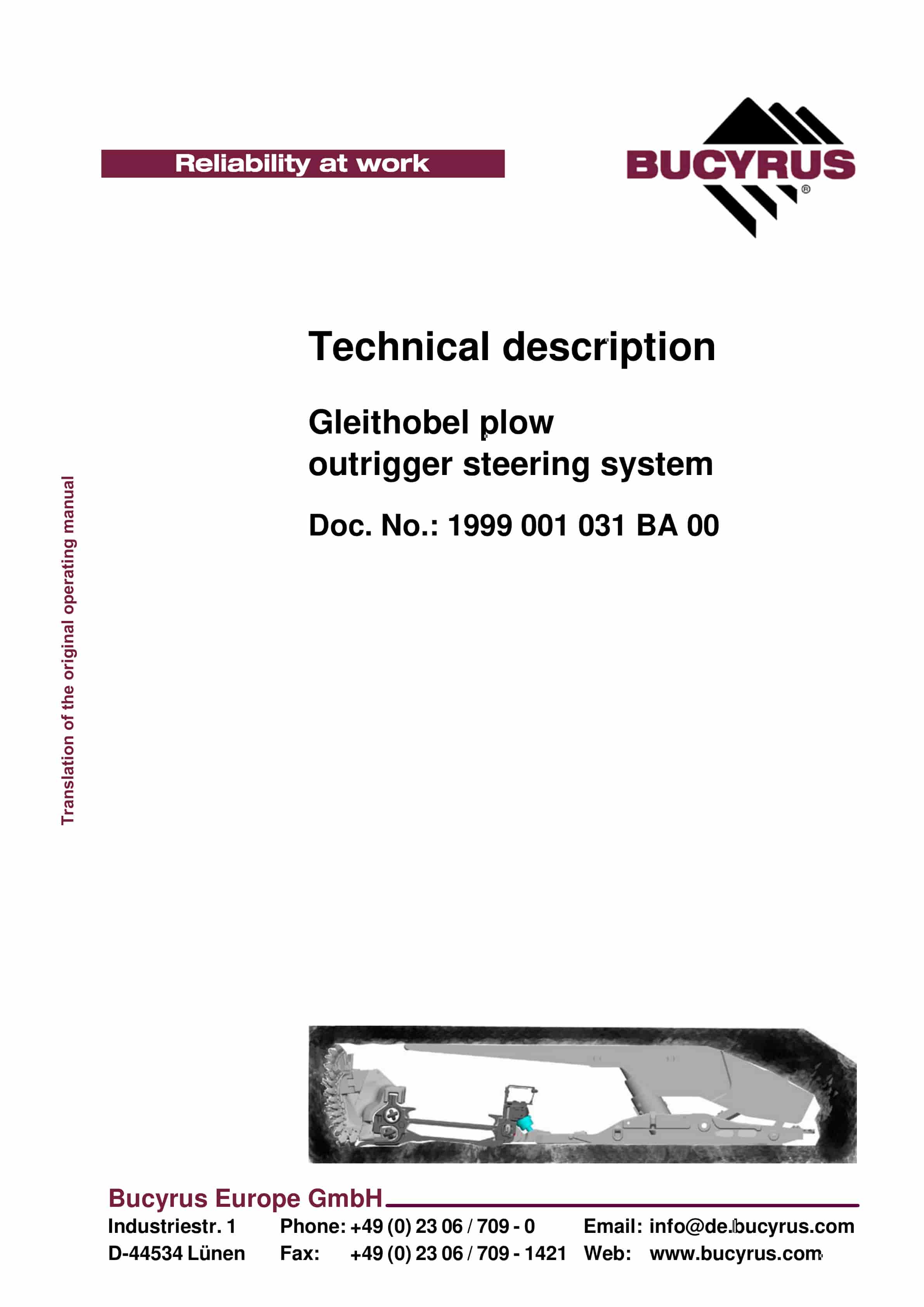
Bucyrus Gleithobel Plow Outrigger Steering System Technical Description 1999 001 031 BA 00
$30.00 Add to cart -
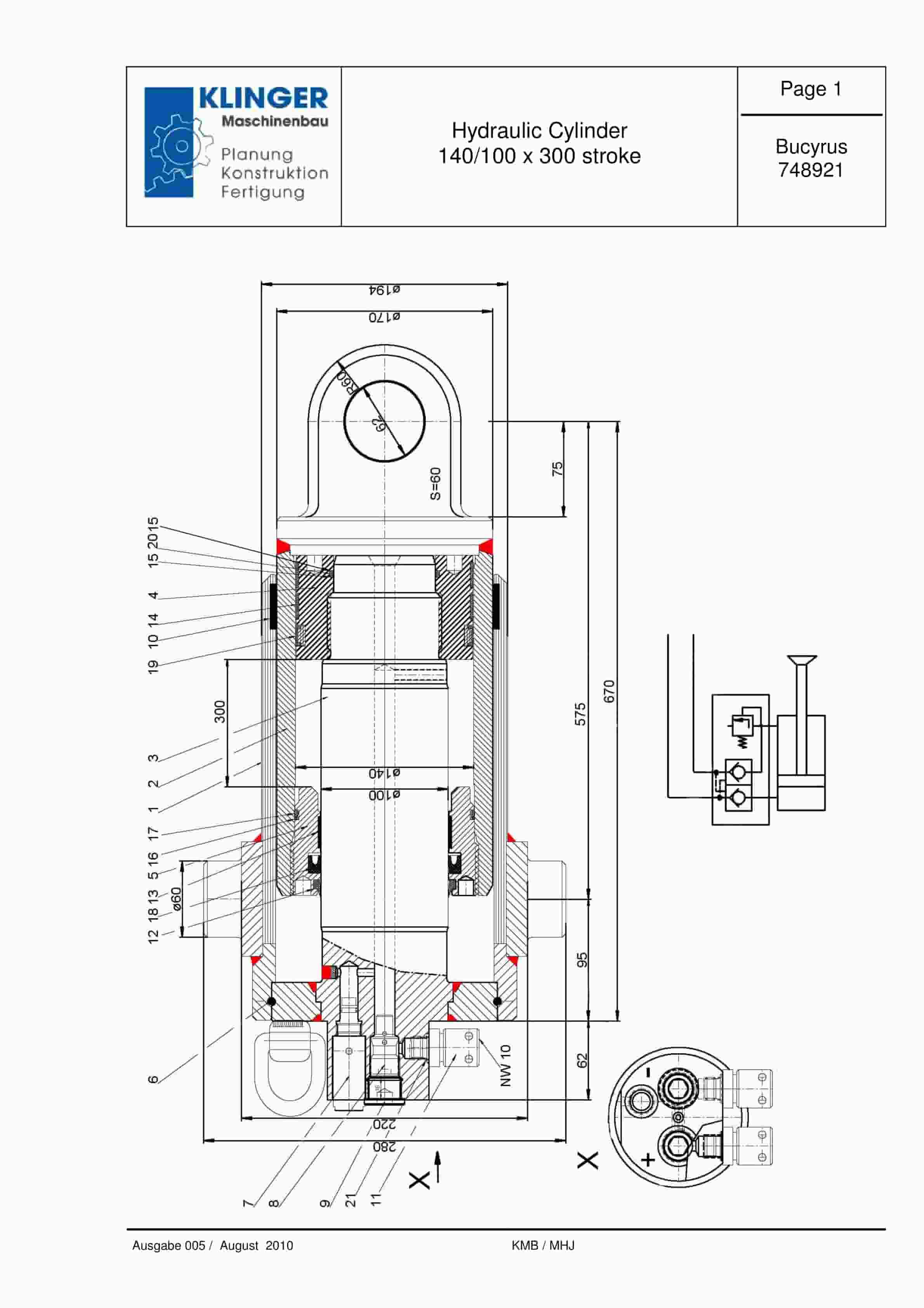
Bucyrus Hydraulic Cylinder 140-100 x 300 Stroke Service Parts List 748921
$30.00 Add to cart -
Bucyrus Continuous Miner Spare Parts List 907783
$30.00 Add to cart -
Bucyrus Continuous Miner Spare Parts List 373608
$30.00 Add to cart -
Bucyrus General Data Technical Handbook 2804198
$30.00 Add to cart


