

BT OS 1.0WL Operator Manual 845118-040
$30.00
- Type Of Manual: Operator Manual
- Manual ID: 845118-040
- : Operator Manual PDF
- Number of Pages: 56
- Size: 2.1MB
- Format: PDF
Product details
-
Model List:
- OS 1.0WL
- 1. Return To HomePage
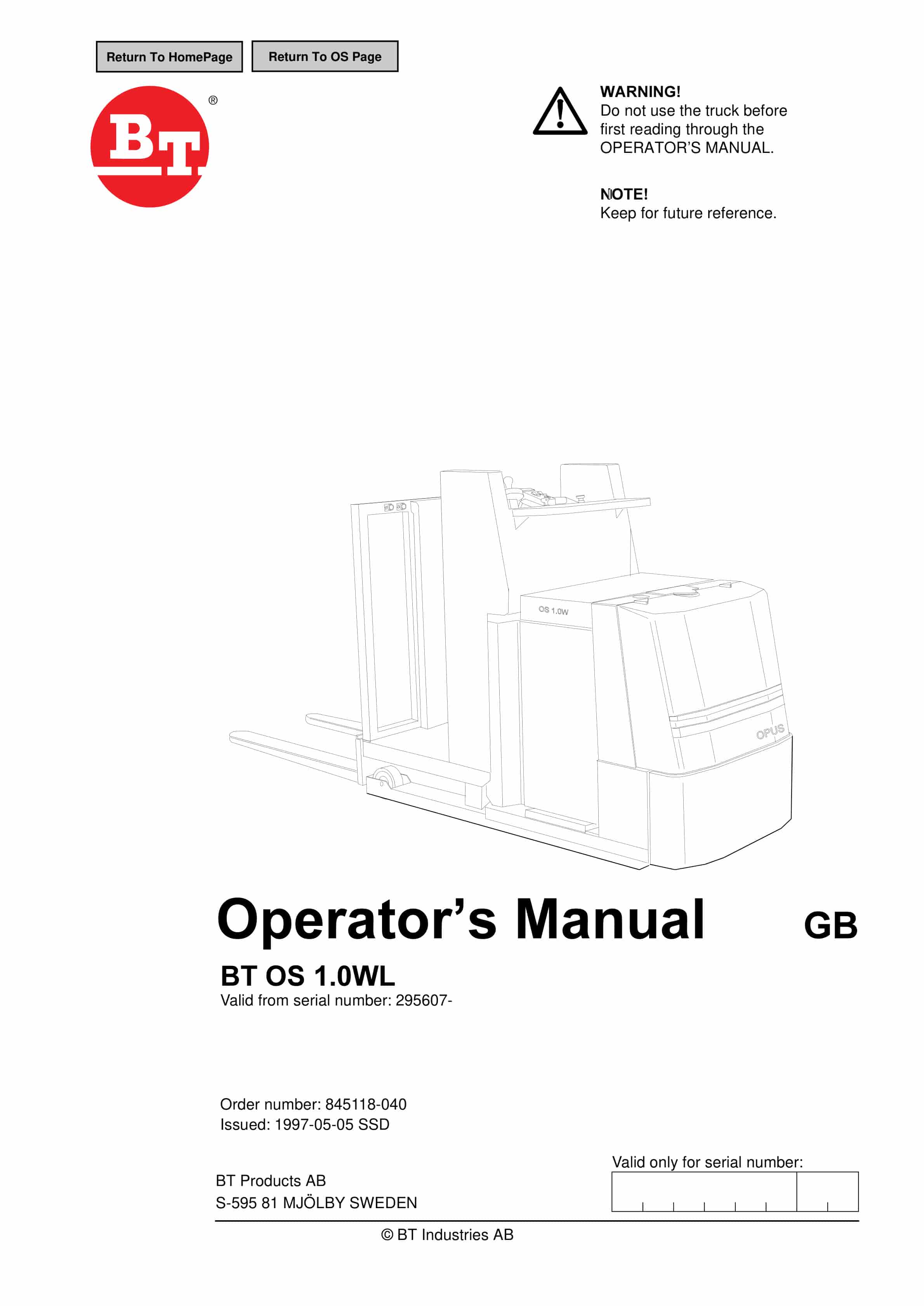
- 2. BT OS 1.0WL
- 2.1. Valid from serial number 295607-
- 2.2. Order number 845118-040
- 2.2.1. Issued 1997-05-05 SSD
- 2.2.1.1. It is important that you read this Operators Manual for your own safety
- 3. Safety regulations
- 3.1. Warning symbols
- 3.1.1. Warning levels
- 3.1.1.1. DANGER
- 3.1.1.2. WARNING
- 3.1.1.3. CAUTION
- 3.1.2. Prohibitory symbols
- 3.1.2.1. NO SMOKING
- 3.1.2.2. NAKED FLAMES PROHIBITED
- 3.1.2.3. GENERAL PROHIBITION
- 3.1.3. Ordinance symbols
- 3.1.3.1. SAFETY SHOES
- 3.1.3.2. PROTECTIVE GLASSES
- 3.2. General safety regulations
- 3.2.1. Operating the truck
- 3.2.2. Operators responsibility
- 3.2.3. Working area
- 3.2.4. Driving and conduct while driving
- 3.2.5. Handling loads
- 3.2.6. Parking the truck
- 3.2.7. Handling the battery
- 3.2.8. Maintenance and repair
- 4. Warning and information plates and symbols
- 4.1. Horn
- 4.2. Hydraulic lever lifting of the platform
- 4.3. Hydraulic lever lowering of the platform
- 4.4. Brake
- 4.5. Travel direction
- 4.6. Hydraulic lever Lifting/lowering of the forks
- 4.7. Identification plate
- 4.8. Capacity plate
- 4.9. Modification plate
- 4.10. Lifting points
- 5. Presentation of the truck
- 5.1. Intended application of the truck
- 5.2. Forbidden application of the truck
- 5.3. Truck data
- 5.3.1. Truck type
- 5.3.2. OS 1.0WL
- 5.4. Truck dimensions
- 5.5. Identification plate
- 5.6. Capacity plate
- 5.7. Modification plate
- 6. Main components
- 6.1. Steering wheel The truck is operated standing in the drivers compartment. Adjustable steering…
- 6.2. Identification plate With model designation, serial number, year of manufacture, weight witho…
- 6.3. Cover Removable which provides good accessibility when servicing.
- 6.4. Castor One adjustable castor wheel to ensure stability.
- 6.5. Electric panel The electrical components are collected on one panel. 24 volt electrical suppl…
- 6.6. Drive unit with brake Drive motor, gears and drive wheel integrated in a compact unit. Steeri…
- 6.7. Electrical steering motor For steering wheel.
- 6.8. Hydraulic unit Pump motor, pump, valves and oil tank integrated in a compact unit.
- 6.9. Serial number The manufacturing number plate fitted to the chassis.
- 6.10. Control circuit fuse 10 A, BT part no. 122308-100.
- 6.11. Fuse for electrical steering wheel 20 A BT part no.122308-200.
- 6.12. Pump motor fuse 100 A, BT part no. 29228.
- 6.13. Drive motor fuse 125 A, BT part no. 29584.
- 6.14. Lifting points For the machine weight, see the identification plate.
- 6.15. Battery/Recharging connector The battery is charged via the permanently fitted charging conn…
- 6.16. Battery 24 V.
- 6.17. Emergency switch off Placed on the top of the instrument panel.
- 6.18. Initial lift mast The forks can be lifted/lowered separately.
- 6.19. Foot pedal Pedal to release the brake and work as a safety switch when lowering the platform.
- 7. Controls and instruments
- 7.1. Lever for adjustment of steering wheel angle
- 7.2. Steering wheel
- 7.3. Controls for raising and lowering the operator platform
- 7.4. Control for lifting and lowering the forks
- 7.5. Travel direction selector and speed control
- 7.6. Brake lever for the travel brake
- 7.7. Horn
- 7.8. Key switch
- 7.9. Display
- 7.10. Emergency switch off
- 7.11. Lever for adjustment of steering wheel height
- 7.12. Lever for adjustment of steering wheel angle (1)
- 7.12.1. WARNING
- 7.13. Steering wheel (2)
- 7.13.1. WARNING
- 7.14. Controls for raising and lowering the operator platform (3)
- 7.15. Control for lifting and lowering the forks (4)
- 7.16. Travel direction selector and speed control (5)
- 7.17. Brake lever for the travel brake (6)
- 7.18. Horn (7)
- 7.19. Key switch (8)
- 7.20. Display (9)
- 7.20.1. Indication steering wheel straight (A)
- 7.20.2. Numerical field (B)
- 7.20.3. Hour meter indicator (C)
- 7.20.4. Parameter control (D)
- 7.20.5. Battery indicator (E)
- 7.20.6. Error indicator (F)
- 7.21. Function
- 7.22. Error codes
- 7.22.1. Code No.
- 7.22.2. Error type
- 7.22.3. Indicator
- 7.22.4. Effect on the truck
- 7.22.4.1. WARNING
- 7.23. Emergency switch off (10)
- 7.24. Lever for adjustment of steering wheel height (11)
- 8. Accessories
- 8.1. Control for driving from the side
- 8.2. Indicating lamp
- 8.3. Extra driving function – low speed
- 8.4. BT TLS Truck Logging System
- 8.5. Logging using a code (5)
- 8.5.1. WARNING
- 8.5.2. WARNING
- 8.5.3. WARNING
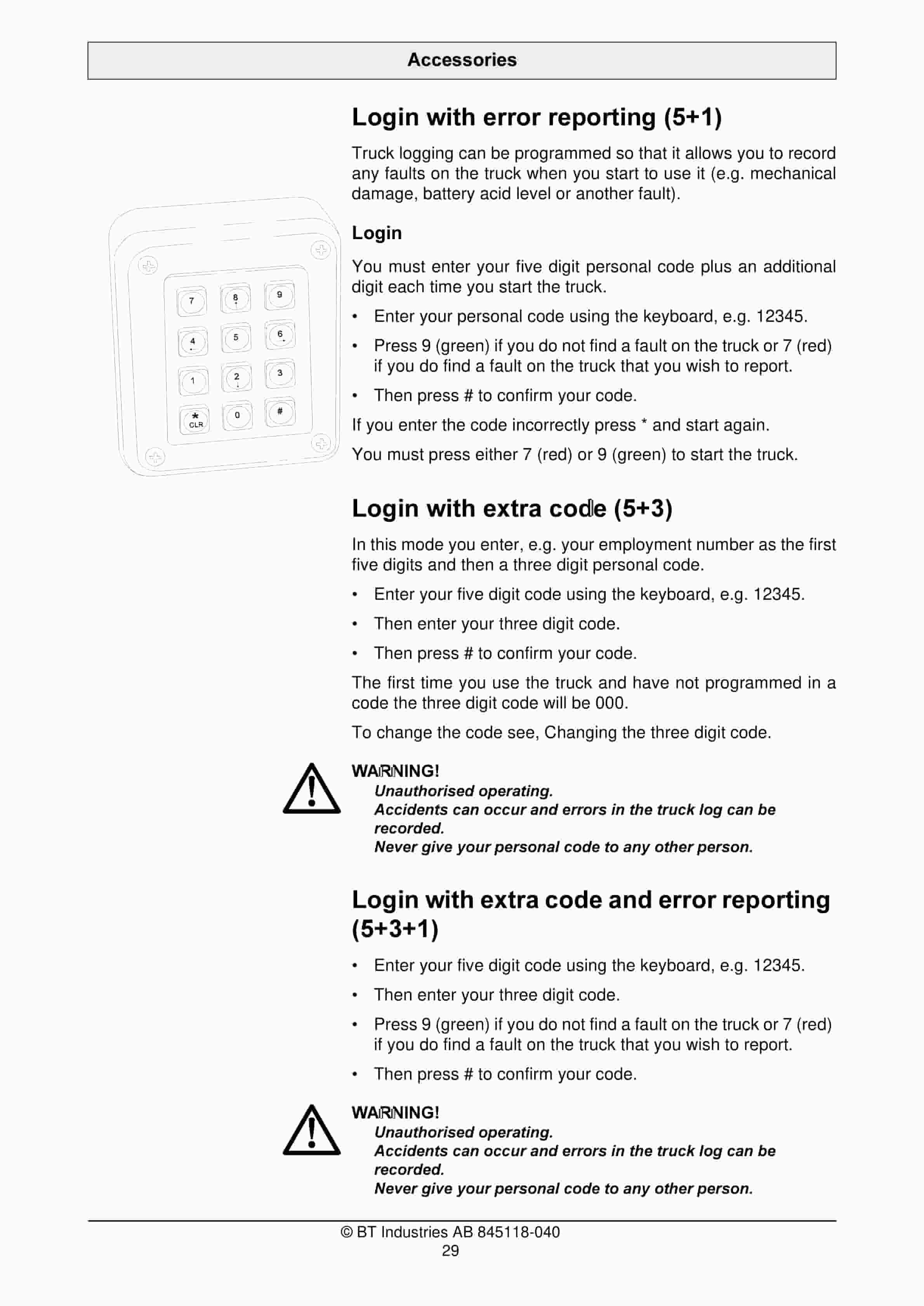
- 8.6. Login with error reporting (51)
- 8.7. Login with extra code (53)
- 8.7.1. WARNING
- 8.8. Login with extra code and error reporting (531)
- 8.8.1. WARNING
- 8.9. Changing the three digit code
- 8.10. Code card
- 8.10.1. WARNING
- 8.10.2. WARNING
- 8.10.3. WARNING
- 8.10.4. Login with error reporting
- 9. Driving
- 9.1. Starting the truck
- 9.1.1. WARNING
- 9.1.2. WARNING
- 9.2. Braking
- 9.3. Steering
- 9.3.1. WARNING
- 9.3.2. WARNING
- 9.4. Parking the truck
- 9.4.1. WARNING
- 10. Transporting loads
- 10.1. WARNING
- 10.2. WARNING
- 10.3. WARNING
- 10.4. WARNING
- 10.5. WARNING
- 10.6. WARNING
- 10.7. Order picking
- 10.7.1. WARNING
- 10.7.2. WARNING
- 10.7.3. WARNING
- 10.8. Collecting a load
- 10.8.1. CAUTION
- 10.9. Depositing a load
- 10.9.1. CAUTION
- 11. Battery
- 11.1. Changing the battery
- 11.1.1. WARNING
- 11.1.2. WARNING
- 11.1.3. WARNING
- 11.2. Charging the battery
- 11.2.1. GENERAL PROHIBITION
- 11.2.2. Battery (Ah)
- 11.2.3. Charger (A)
- 11.2.3.1. WARNING
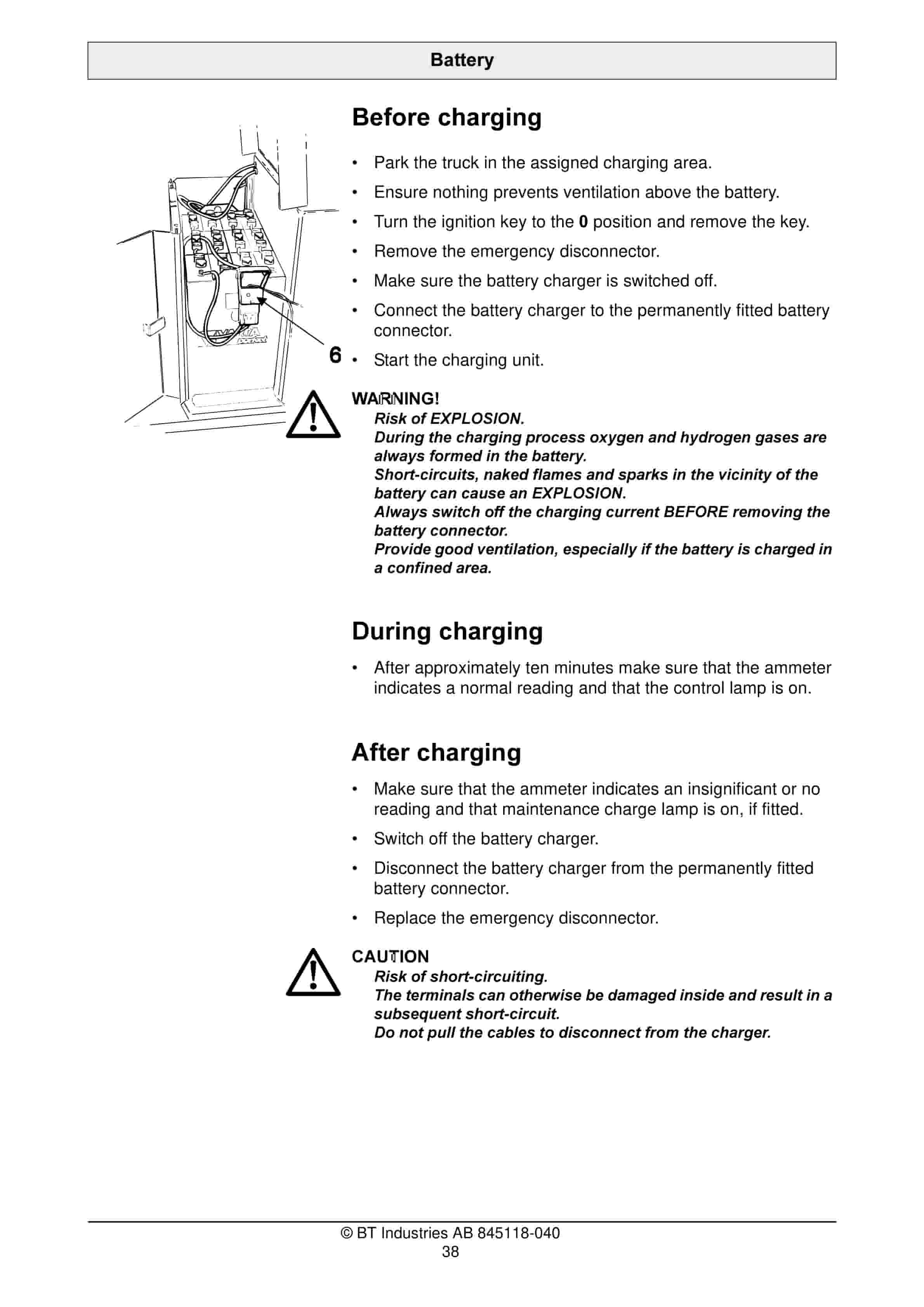
- 11.2.4. Before charging
- 11.2.4.1. WARNING
- 11.2.5. During charging
- 11.2.6. After charging
- 11.2.6.1. CAUTION
- 11.3. Battery maintenance
- 11.3.1. WARNING
- 11.3.2. Each week
- 11.3.3. Each month
- 11.3.3.1. Temperature C
- 11.3.3.2. Density g/cm3
- 12. Daily service and function checks
- 12.1. WARNING
- 12.2. Pos no.
- 12.3. Check points
- 13. Maintenance
- 13.1. Safety regulations with maintenance work
- 13.1.1. WARNING
- 13.1.2. WARNING
- 13.1.3. WARNING
- 13.1.4. CAUTION
- 13.1.5. WARNING
- 13.2. Maintenance work that can be carried out by the operator
- 13.3. Maintenance work that may be carried out by trained maintenance personnel
- 13.4. Cleaning and washing
- 13.4.1. External cleaning
- 13.4.2. Cleaning the motor compartment
- 13.4.3. Electrical components
- 13.5. Maintenance chart
- 13.5.1. Pos. no.
- 13.5.2. Work to carry out
- 13.5.2.1. Intervals in hours
- 13.5.2.2. Intervals in days/weeks/months
- 13.6. Lubrication chart
- 13.6.1. Service point
- 13.6.2. Interval/Running hours
- 13.6.3. Lubricant
- 13.7. Oil and grease specification
- 13.7.1. Lubricant
- 13.7.2. Specification
- 13.7.3. Application area
- 13.7.4. > – 15C
- 13.7.5. < – 15C
- 14. Transporting and storing the truck
- 14.1. The trucks dimensions and weight as standard
- 14.2. Lifting the truck
- 14.2.1. WARNING
- 14.2.2. WARNING
- 14.3. Towing and transporting a defective truck
- 14.4. Storing the truck
- 14.4.1. Battery
- 14.4.2. Hydraulic system
- 14.4.3. Drive unit
- 14.5. Starting after a period of disuse
- 15. Recycling/discarding
- 15.1. Discarding the battery
- 15.2. Scrapping the truck
- 15.2.1. Chassis
- 15.2.2. Hydraulic system
- 15.2.3. Electrical system
Related products
-
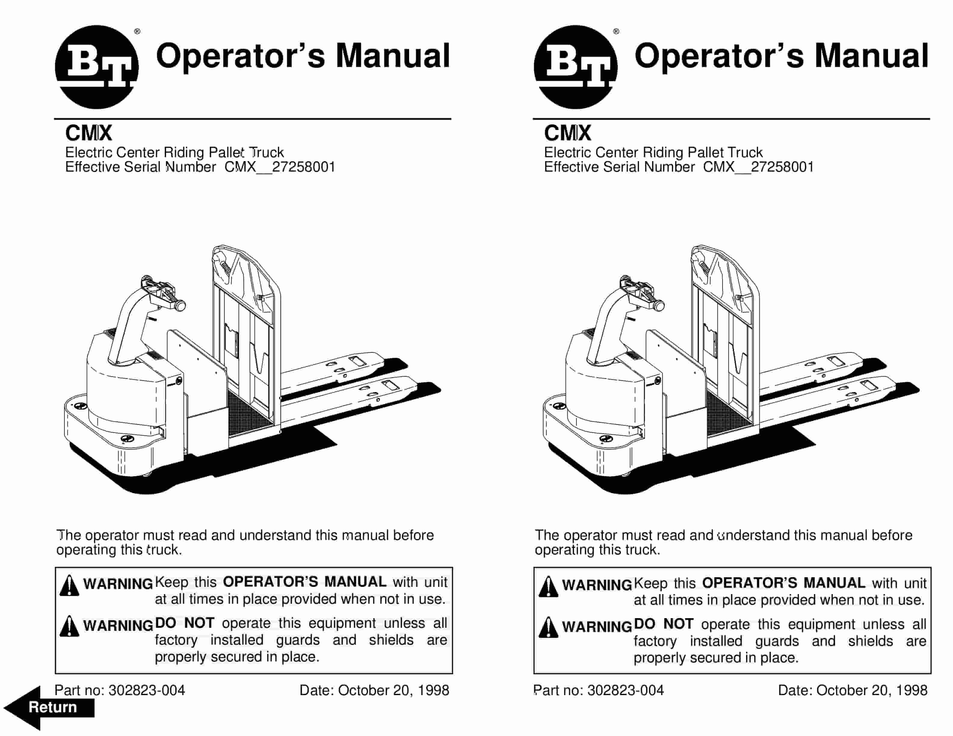
BT CMX Electric Center Riding Pallet Truck Operator Manual 302823-004
$30.00 Add to cart -
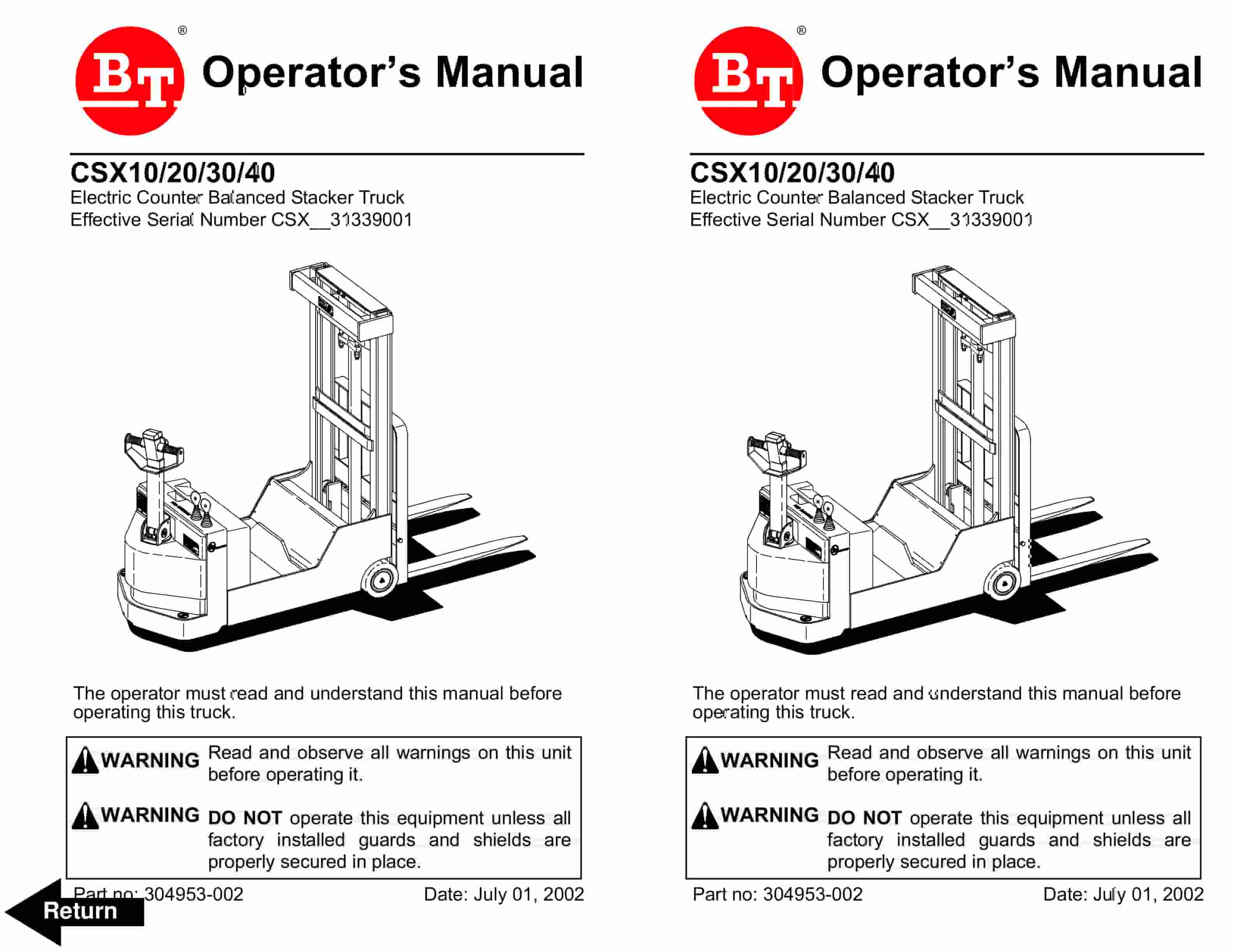
BT CSX Electric Counter Balanced Stacker Truck Operator Manual 304953-002
$30.00 Add to cart -
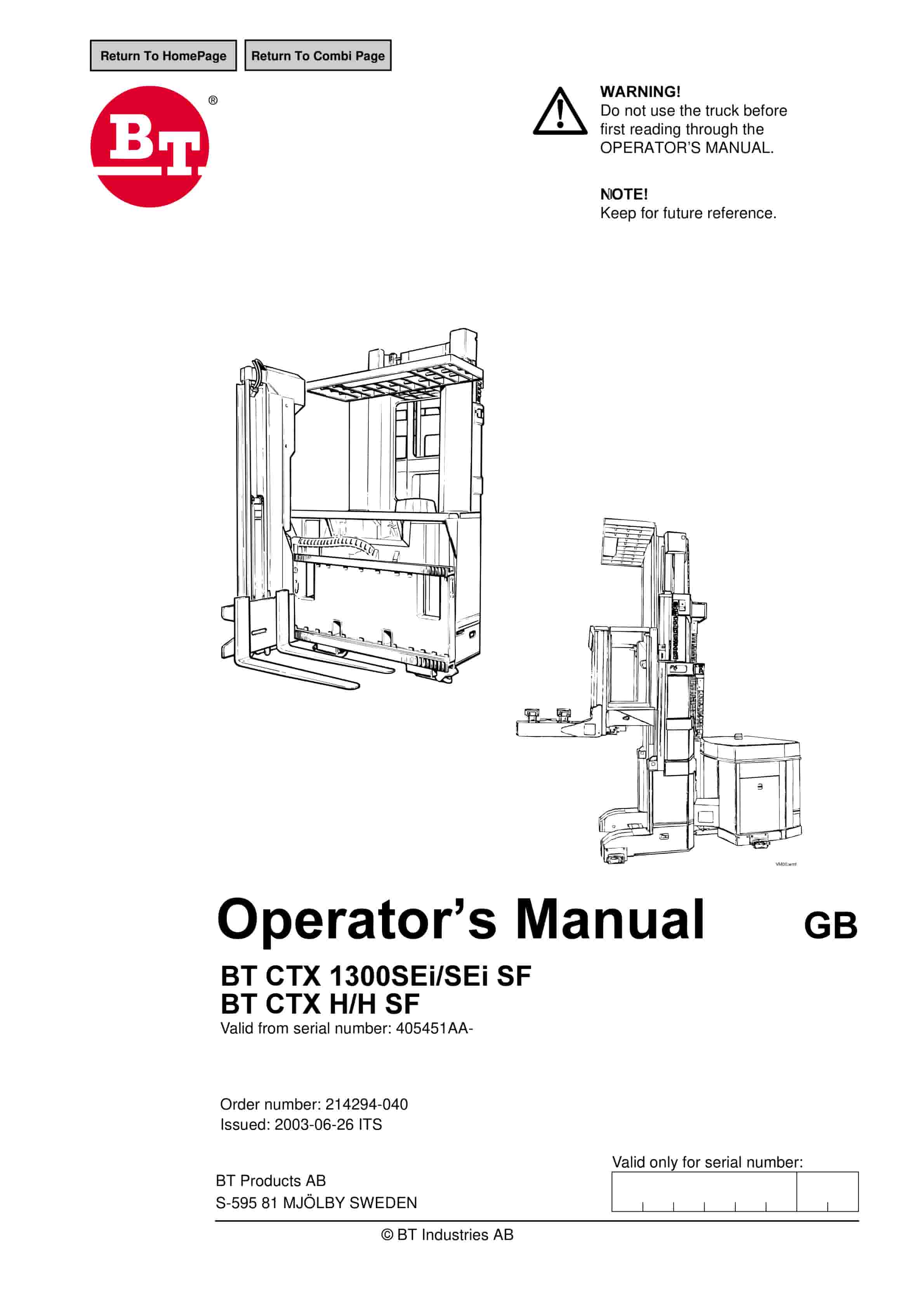
BT CTX1300SEi, CTX1300SEi SF, CTX H, CTX H SF Operator Manual 214294-040
$30.00 Add to cart -
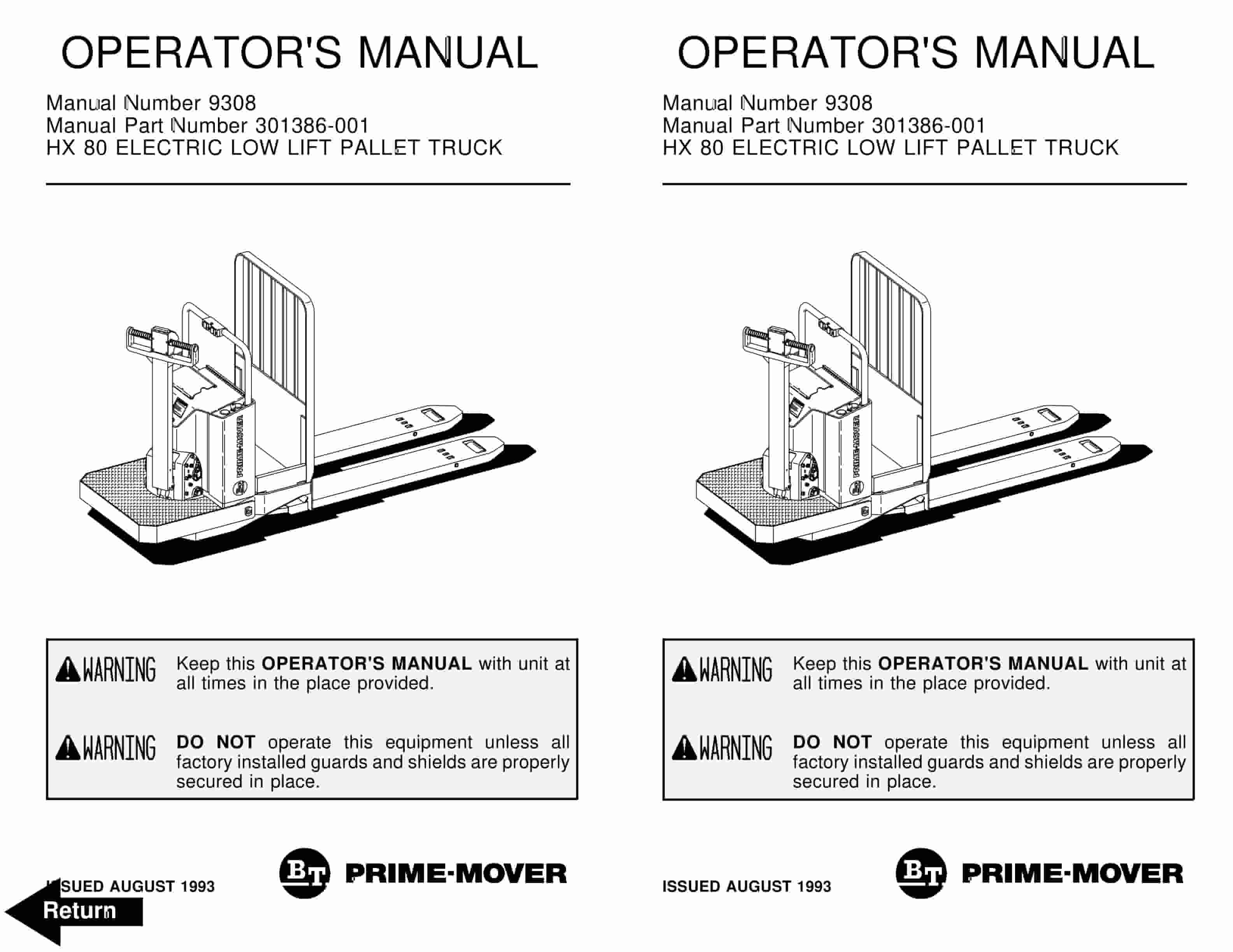
BT HX-80 Electric Low Lift Pallet Truck Operator Manual 301386-001
$30.00 Add to cart -
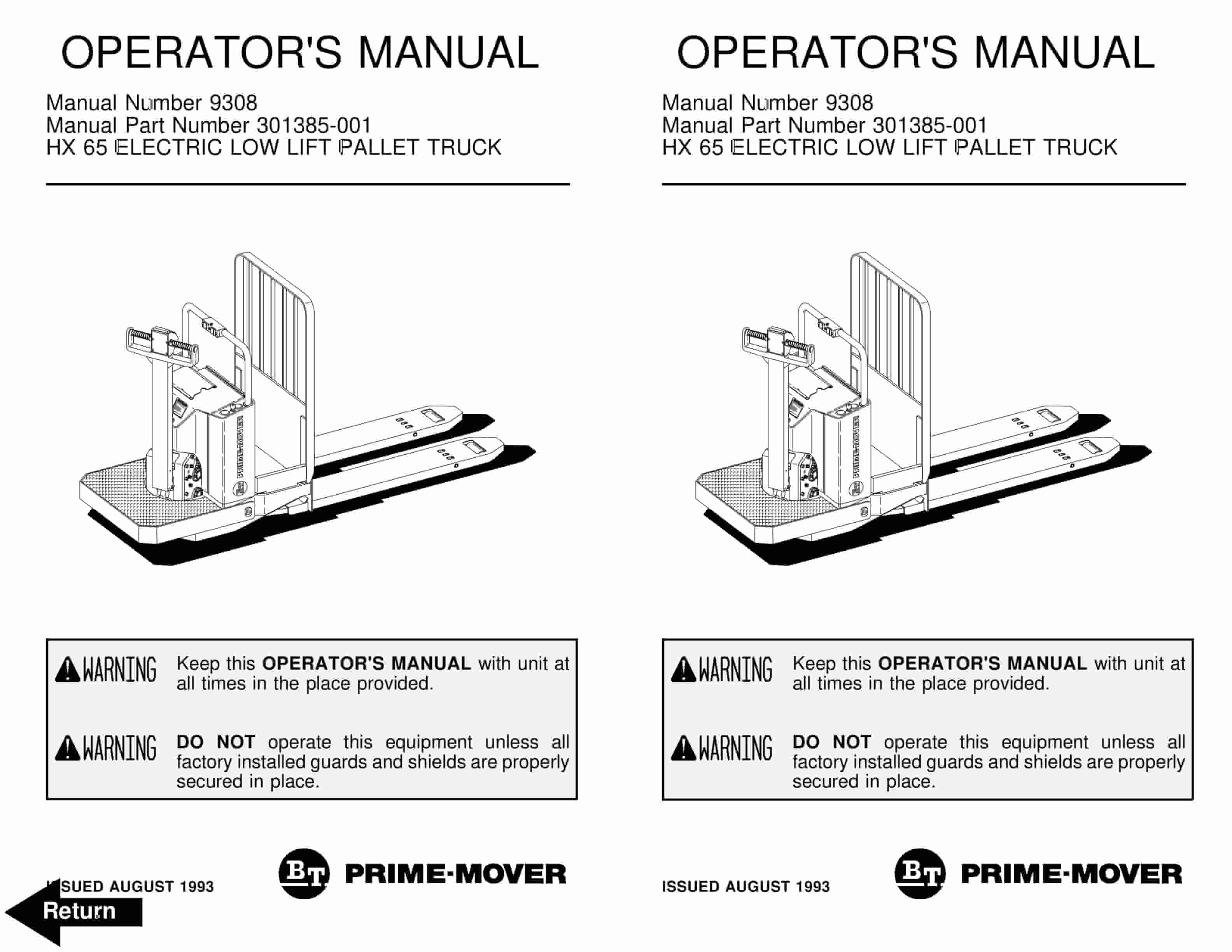
BT HX-65 Electric Low Lift Pallet Truck Operator Manual 301385-001
$30.00 Add to cart


