

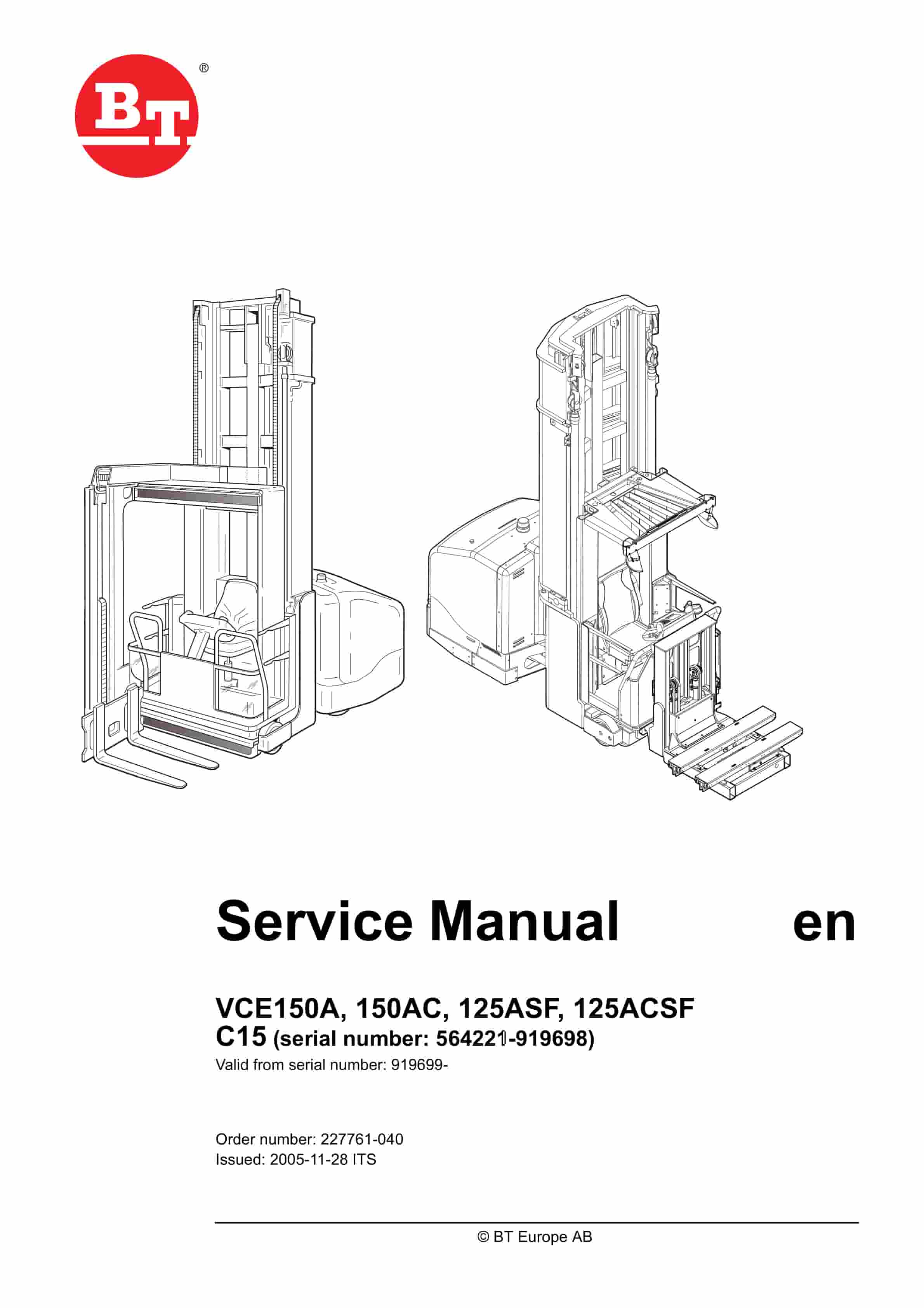
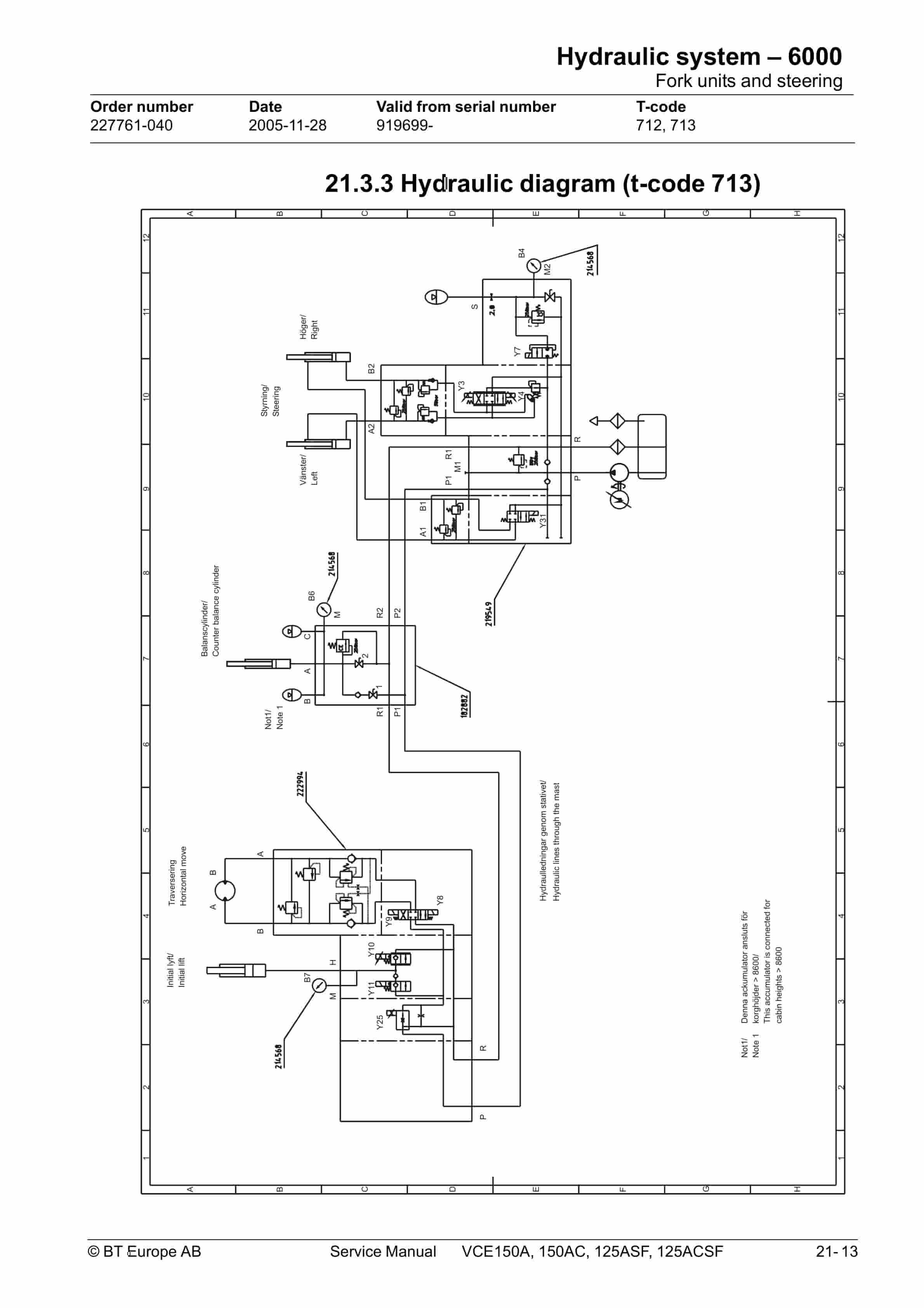
BT VCE150A, VCE150AC, VCE125ASF, VCE125ACSF Service Manual 227761-040
$30.00
- Type Of Manual: Service Manual
- Manual ID: 227761-040
- : Service Manual PDF
- Number of Pages: 608
- Size: 35.3MB
- Format: PDF
Product details
-
Model List:
- VCE150A, VCE150AC, VCE125ASF, VCE125ACSF
- 1. Content
- 2. Presentation of the truck – M2 (t-code 712)
- 2.1. Ergonomics
- 2.2. Performance
- 2.3. Electrical system
- 2.3.1. Intended application of the truck
- 2.3.2. Forbidden application of the truck
- 2.4. Truck data
- 2.5. Truck dimensions
- 2.6. Identification plate
- 2.7. Capacity plate
- 2.8. Additional plates (VNA)
- 2.9. Modification plate
- 2.10. Identification plate, mast
- 2.11. Main components
- 2.12. Warning and information plates and symbols
- 3. Presentation of the truck – M2 (t-code 713)
- 3.1. Intended application of the truck
- 3.2. Prohibited application of the truck
- 3.3. Truck data
- 3.4. Truck dimensions
- 3.4.1. VCE125ASF
- 3.5. Identification plate
- 3.6. Capacity plate
- 3.7. Additional plates (VNA)
- 3.8. Modification plate
- 3.9. Identification plate, mast
- 4. Introduction, maintenance – P1 (t-code 712)
- 4.1. Safety precautions for maintenance work
- 4.1.1. Gas-charged accumulators
- 4.2. Maintenance work to be performed by the operator
- 4.2.1. Maintenance work that may be performed by trained service technicians
- 4.3. Cleaning and washing
- 4.3.1. Exterior cleaning
- 4.3.2. Cleaning the motor compartment
- 4.3.3. Electric components
- 4.4. Secure lifting
- 4.5. Lifting points
- 4.5.1. Lifting the truck
- 5. Maintenance – P1 (t-code 713)
- 5.1. Safety regulations with maintenance work
- 5.1.1. Gas-charged accumulators
- 5.1.2. Maintenance work that is to be carried out by the operator
- 5.1.3. Maintenance work that may be carried out by trained maintenance personnel
- 5.2. Cleaning and washing
- 5.2.1. External cleaning
- 5.2.2. Cleaning the motor compartment
- 5.2.3. Electrical components
- 5.3. Transporting and storing the truck
- 5.3.1. Lifting the truck
- 5.3.2. Towing and transporting a defective truck
- 5.3.3. Storing the truck
- 5.4. Starting after a period of disuse
- 6. Preventive maintenance – P2 (t- code 712)
- 6.1. Maintenance schedule
- 7. Preventive maintenance – P2 (t-code 713)
- 8. Oil and grease specifications – P3 (T-code 712)
- 9. Oil and grease specification – P3 (t-code 713)
- 10. Tools – P4
- 10.1. Super Seal contact
- 10.1.1. AMP connector
- 10.1.2. Diverse tools
- 11. Chassis – 0000 Truck installation
- 11.1. General
- 11.2. Tool list
- 11.3. Unloading the truck
- 11.3.1. Unloading a standing truck
- 11.3.2. Unloading a truck lying down
- 11.3.3. Unloading the truck using cranes
- 11.3.4. Erecting the truck
- 11.3.5. Final assembly
- 11.3.6. Assembly of the initial mast
- 11.4. Preparations for commissioning
- 11.5. Installation in narrow aisle
- 11.5.1. General
- 11.5.2. Rail-guided truck
- 11.5.3. Wire-guided truck
- 12. General tightening torque – 0400
- 12.1. Galvanised, non oiled bolts
- 12.2. Untreated, oiled bolts
- 12.3. Tightening torque
- 13. Electric pump motor – 1710.1
- 13.1. General
- 13.2. Disassembled pump motor
- 13.3. Disassembly and assembly of the pump motor
- 13.3.1. Disassembly
- 13.3.2. Assembly
- 13.4. Replacing the ball bearing
- 13.4.1. Disassembly
- 13.4.2. Assembly
- 13.5. Assembly instruction for the external temperature sensor
- 14. Electric pump motor – 1710.2
- 14.1. General
- 14.2. Disassembled pump motor
- 14.2.1. Connection
- 14.3. Disassembly and assembly of the pump motor
- 14.3.1. Disassembly
- 14.3.2. Assembly
- 14.4. Replacing the ball bearing
- 14.4.1. Disassembly (D side)
- 14.4.2. Assembly
- 14.4.3. Disassembly (N side)
- 14.4.4. Assembly (N side)
- 14.4.5. Carbon brushes and carbon brush-rocker
- 15. Electric drive motor – 1760
- 15.1. General
- 15.2. Disassembled drive motor
- 15.3. Disassembly and assembly of the drive motor
- 15.3.1. Disassembly of the drive motor
- 15.3.2. Assembly of the drive motor
- 15.4. Replacing the ball bearing
- 15.4.1. Assembly
- 15.5. Assembly instruction for the external temperature sensor
- 16. Drive unit/gear – 2550
- 16.1. General
- 16.2. Components/data of the drive unit and gear
- 16.2.1. Component identification
- 16.2.2. Technical data
- 16.2.3. Dismantled gear
- 16.3. Replacing the drive motor/drive gear
- 16.3.1. Dismantling of drive unit from truck
- 16.3.2. Fitting the drive unit in truck
- 16.3.3. Dismantling the drive motor and the gear
- 16.3.4. Fitting the drive motor and the gear
- 16.4. Oil level check/replacement
- 16.4.1. Checking/filling of oil
- 16.4.2. Oil replacement
- 16.5. Repairs
- 16.5.1. Replacing the drive shaft sealing ring
- 16.5.2. Leakage from the top cover
- 16.5.3. Leakage from the lower cover
- 16.5.4. Replacing the wheel bolt
- 17. Travel brake system – 3100
- 17.1. General
- 17.2. Operating description
- 17.2.1. Releasing the accelerator
- 17.2.2. Travel direction selector
- 17.2.3. Pressing down the brake pushbutton
- 17.2.4. Parking brake
- 17.2.5. Emergency braking
- 17.3. Electromechanical disc brake, drive motor
- 17.3.1. Assembling
- 17.3.2. Dismantling
- 17.3.3. Inspection
- 17.3.4. Assembling
- 17.4. Maintenance
- 17.4.1. Adjusting the play
- 17.4.2. Wear
- 17.4.3. Check the braking force
- 17.5. Multiple disc brake, support arm
- 17.5.1. Assembling
- 17.5.2. Dismantling
- 17.5.3. Inspection
- 17.5.4. Assembling
- 17.6. Maintenance
- 17.6.1. Adjusting the play
- 18. Drive wheel – 3530
- 18.1. General
- 18.2. Dismantling the drive wheel
- 18.3. Assembling the drive wheel
- 19. Fork/support arm wheel – 3550
- 19.1. Dismantling the wheel
- 19.2. Assembling the wheel
- 19.2.1. mm wheel with brake and 350 mm wheel
- 19.3. Dismantling/assembling the wheel bearings
- 19.3.1. mm wheel with brake and 350 mm wheel
- 20. Hydraulic system – 6000
- 20.1. General
- 20.1.1. Symbols
- 20.2. Cabin lifting
- 20.2.1. General
- 20.2.2. Cabin lifting – S44 closed
- 20.2.3. Cabin lowering – S70 closed
- 20.2.4. AC hydraulic unit, components
- 20.2.5. Hydraulic flow diagram, cabin lifting
- 20.2.6. B cylinder system
- 20.3. Fork units and steering
- 20.3.1. General
- 20.3.2. Hydraulic flow diagram, DC system (t-code 712)
- 20.3.3. Hydraulic diagram (t-code 713)
- 20.3.4. Shuttle fork valve blocks (Tcode 713)
- 20.3.5. Fork rotation (t-code 712)
- 20.3.6. Traversing movement
- 20.3.7. Fork lifting
- 20.3.8. Fork lowering
- 20.3.9. Steering
- 20.4. Extra hydraulic function (T-code 712)
- 20.4.1. Valves used for the extra hydraulic functions
- 20.4.2. Hydraulic diagram, extra hydraulic function (t-code 712)
- 21. Hydraulic pump – 6140
- 21.1. General
- 21.2. Replacing the hydraulic pump
- 21.2.1. Dismantling
- 21.2.2. Assembling
- 22. Main mast and mast – 7100
- 22.1. Setting the cab and mast stoppers
- 22.1.1. Cab stoppers
- 22.1.2. Setting the cab stoppers
- 22.1.3. Mast stoppers
- 23. Main lift chain system – 7120
- 23.1. General
- 23.2. Checking the chain setting
- 23.3. Chain inspection
- 23.3.1. Noise
- 23.3.2. Surface rust
- 23.3.3. Rusty links
- 23.3.4. Stiff links
- 23.3.5. Bolt rotation
- 23.3.6. Loose bolts
- 23.3.7. Outline wear
- 23.3.8. Stretching
- 23.3.9. Damage
- 23.3.10. Damaged discs
- 23.3.11. Damaged bolts
- 23.3.12. Dirty chain
- 23.4. Cleaning
- 23.5. Lubrication
- 24. Initial mast/Turret head fork unit – 7200 (t-code 712)
- 24.1. General
- 24.2. Assembly/disassembly of the initial mast
- 24.2.1. Mast assembly
- 24.2.2. Installation of belts on a new truck
- 24.2.3. Installing the hydraulic hose and electric cabling
- 24.2.4. Mast disassembly
- 24.3. Inspection and replacement of belts used for fork traversing
- 24.3.1. Inspection
- 24.3.2. Replacing the belt
- 24.3.3. Checking belt tensioning
- 24.4. Friction plate adjustment
- 25. Shuttle fork unit – 7800 (t-code 713)
- 25.1. Assembling shuttle forks
- 25.2. Maintenance
- 25.2.1. Maintenance schedule
- 25.2.2. Lubrication
- 25.2.3. Adjustment of chains
- 25.3. Replacement of shuttle fork unit
- 26. Wire guidance equipment – 8200
- 26.1. General
- 26.2. Generator
- 26.2.1. Technical data
- 27. Control/computer equipment – 8700
- 27.1. General
- 27.2. Connection
- 27.2.1. Specifications
- 27.3. Truck software management on the PC
- 27.3.1. Downloading the software package via the network
- 27.4. Connecting to the truck
- 27.4.1. Connecting to the truck
- 27.4.2. Menu window tree
- 27.4.3. Disconnection
- 27.5. Menus
- 27.5.1. File menu
- 27.5.2. View menu
- 27.5.3. Tools menu
- 27.5.4. Option menu
- 27.6. Download package, Function for firmware downloading
- 27.6.1. Normal firmware download
- 27.6.2. Emergency download
- 27.7. Using the menu tree to verify/ change parameters and perform diagnostics
- 27.7.1. Software
- 27.7.2. Parameters
- 27.7.3. Diagnostics/troubleshooting
- 27.8. Installation
- 27.8.1. Installation of TruckCom SE on a PC
- 27.8.2. Necessary changes in Windows XP and Windows 2000 for TruckCom SE
- 27.8.3. In case of communication errors with the CAN
- 27.8.4. To uninstall
- 28. Height pre-selection – 9390
- 28.1. General
- 28.2. Parameters
- 28.2.1. MCU parameters
- 28.3. Programming
- 28.3.1. Programming a level
- 28.3.2. Operation/Automatic operations
- 29. SM.VCESF_5000.pdf
- 29.1. Electrical system – 5000
- 29.1.1. General
- 29.1.2. Main Computer Unit, MCU (A5)
- 29.1.3. Fork computer unit, FCU (A4)
- 29.1.4. Integrated Control Panel, ICP (A16)
- 29.1.5. AC regulators, ACTL (A1), ACTR (A31) and ACH (A2)
- 29.1.6. DC regulator, DCHI (A32)
- 29.1.7. Parameters
- 29.1.8. Electrical system, overview
- 29.1.9. List of symbols and electric circuit diagrams
- 29.1.10. Component list
- 29.1.11. Functional description, General
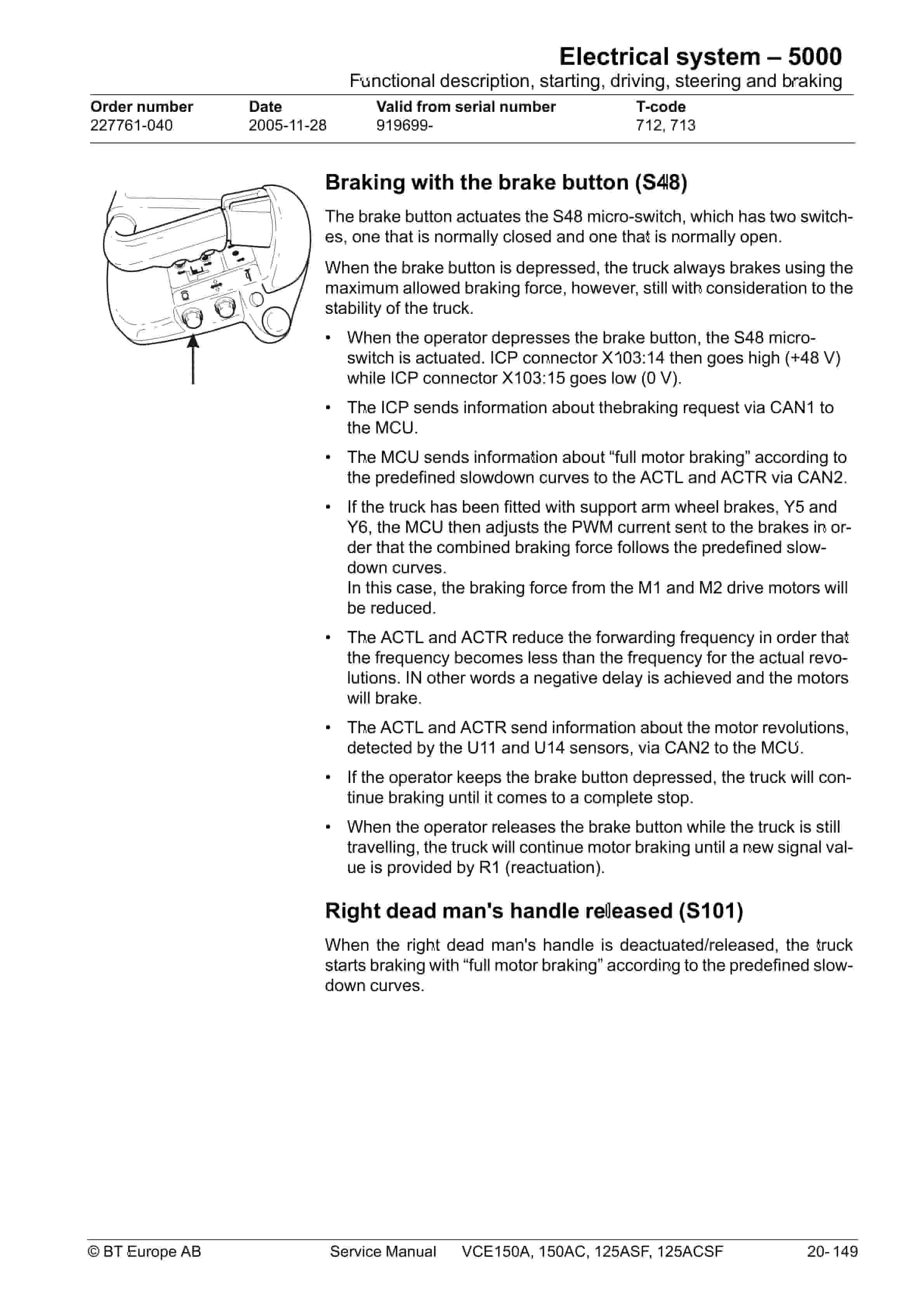
- 29.1.12. Functional description, starting, driving, steering and braking
- 29.1.13. Electrical description of the hydraulic functions
- 29.1.14. Turret head unit (T-code 712)
- 29.1.15. Shuttle fork unit (t-code 713)
- 29.1.16. Wire guidance
- 29.1.17. Display
- 29.1.18. Calibration Turret Head (t-code 712)
- 29.1.19. Calibration Shuttle fork (t-code 713)
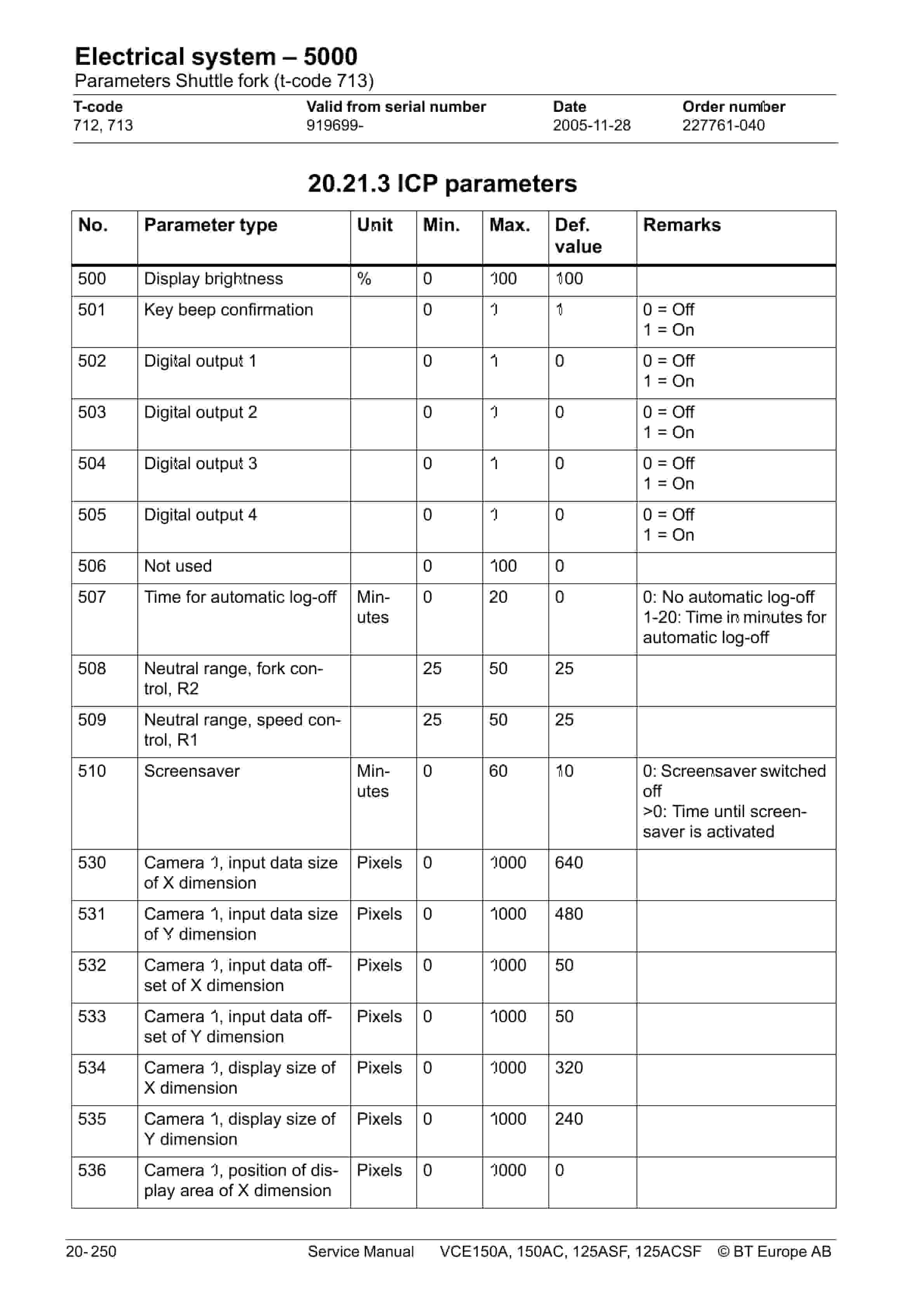
- 29.1.20. Parameters
- 29.1.21. Parameters Shuttle fork (t-code 713)
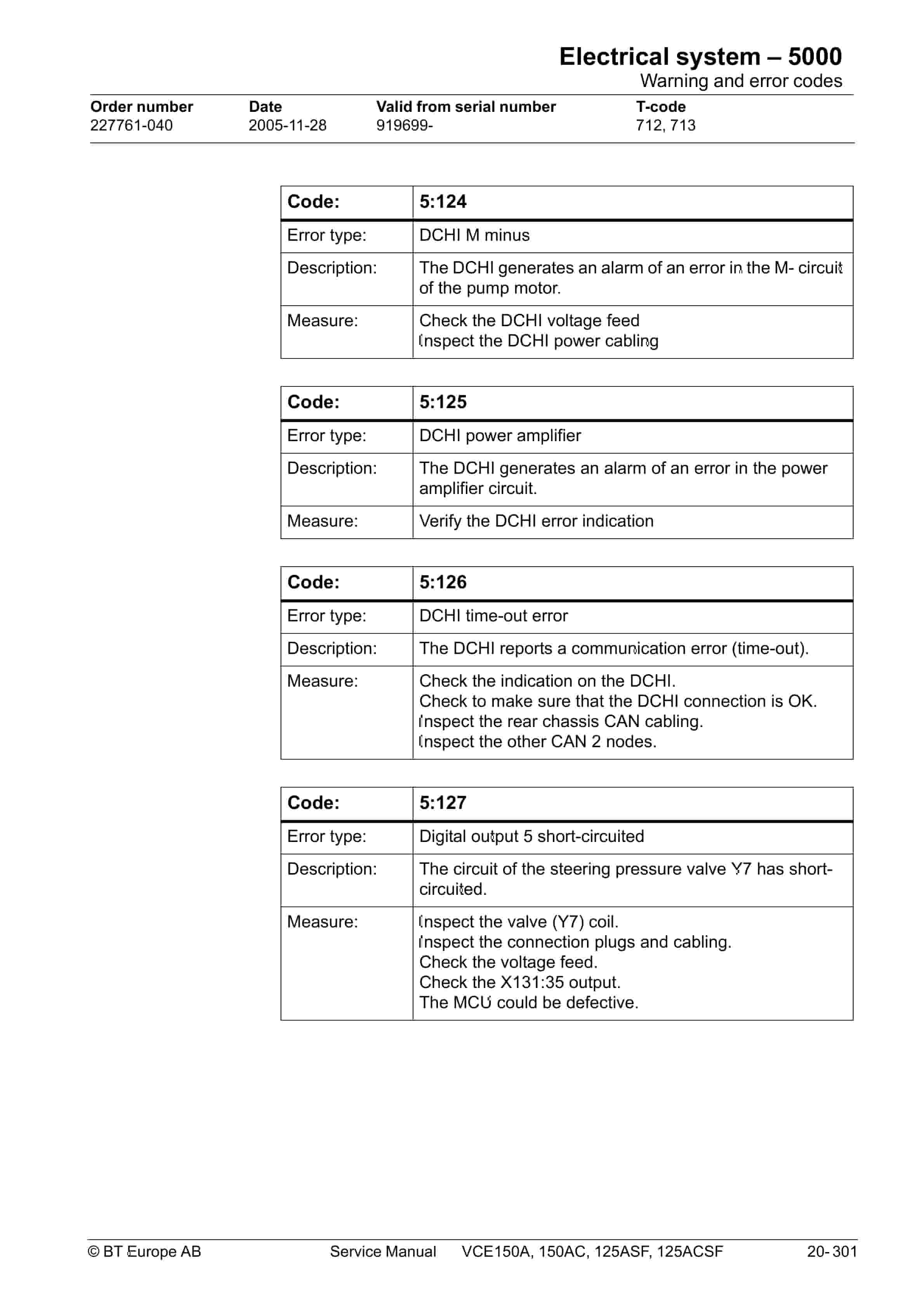
- 29.1.22. Warning and error codes
- 29.1.23. Warning and error codes
Related products
-
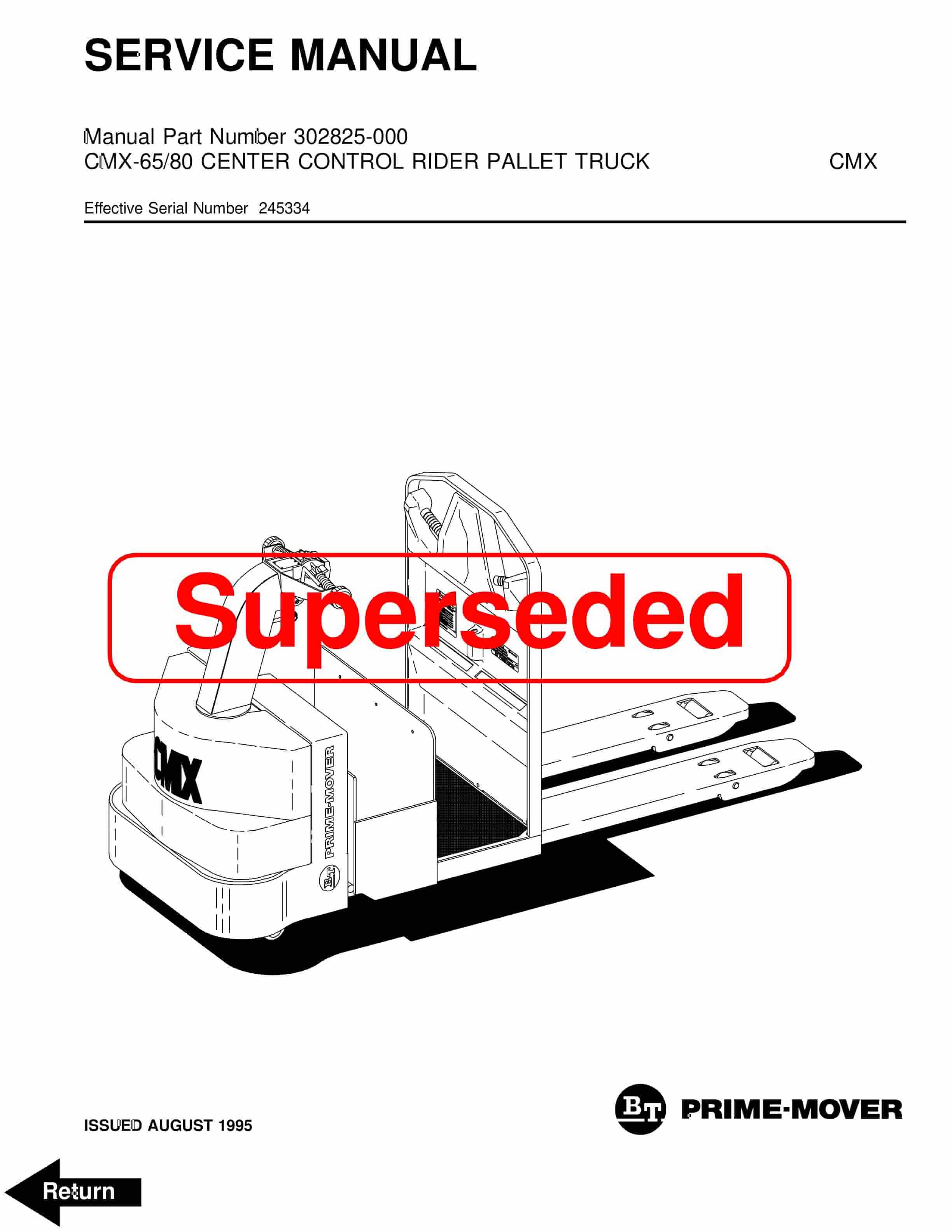
BT CMX-65, CMX-80 Center Control Riding Pallet Truck Service Manual 302825-000
$30.00 Add to cart -
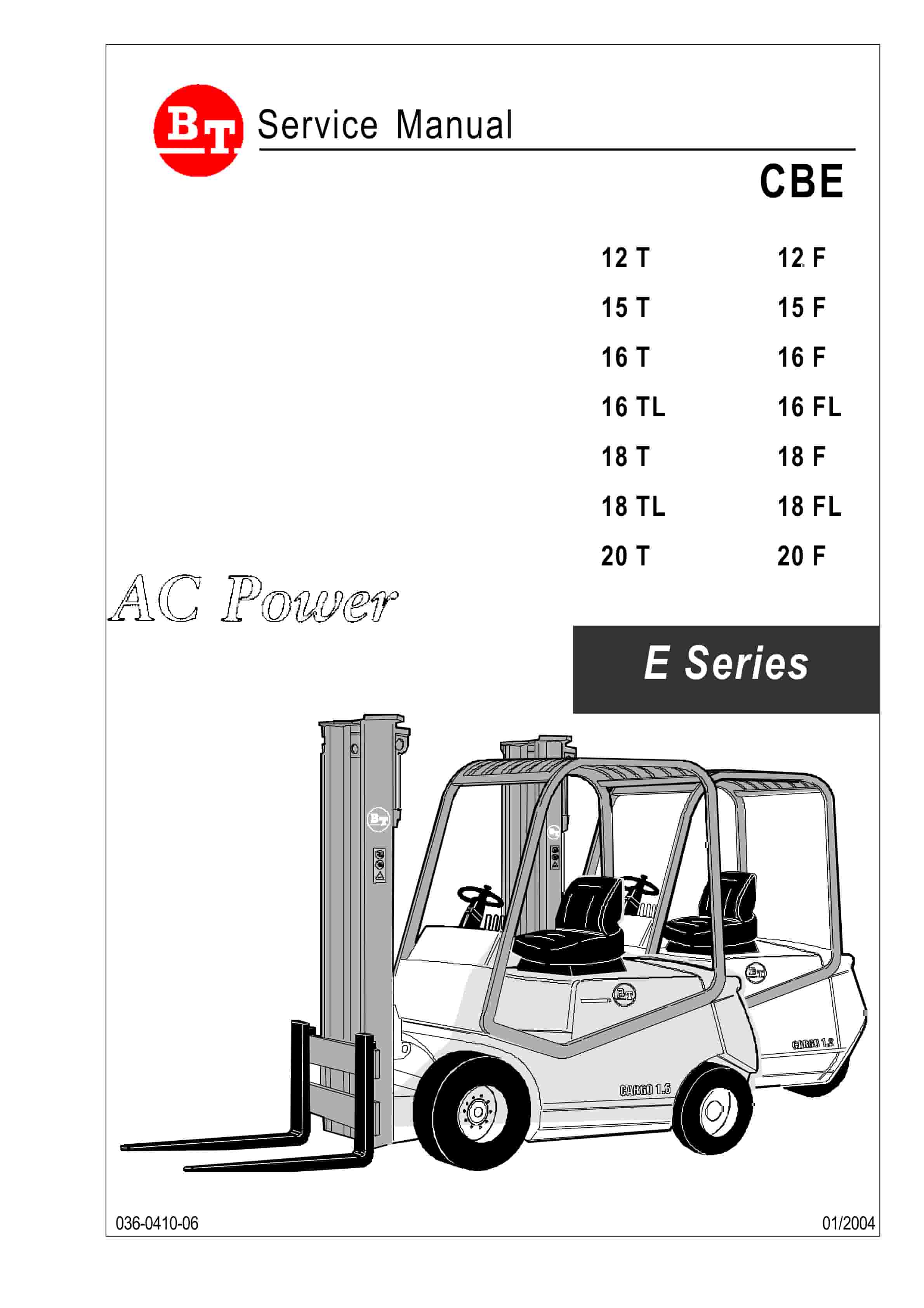
BT CBE 12T to CBE 20F Service Manual 036-0410-03
$30.00 Add to cart -
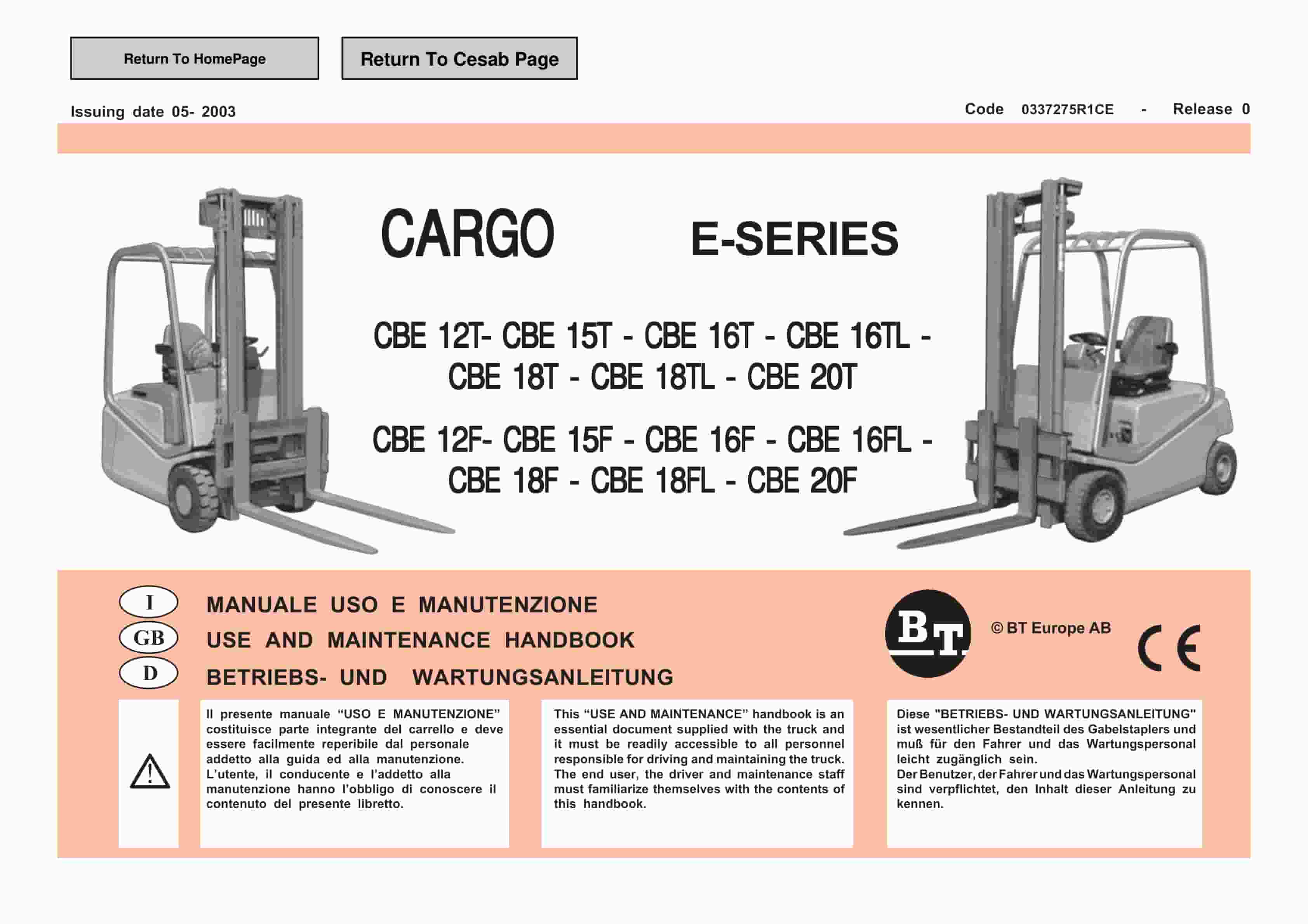
BT CARGE E-Series CBE 12T-20T, CBE 12F-20F Use And Maintenance Handbook 0337275R1CE
$30.00 Add to cart -
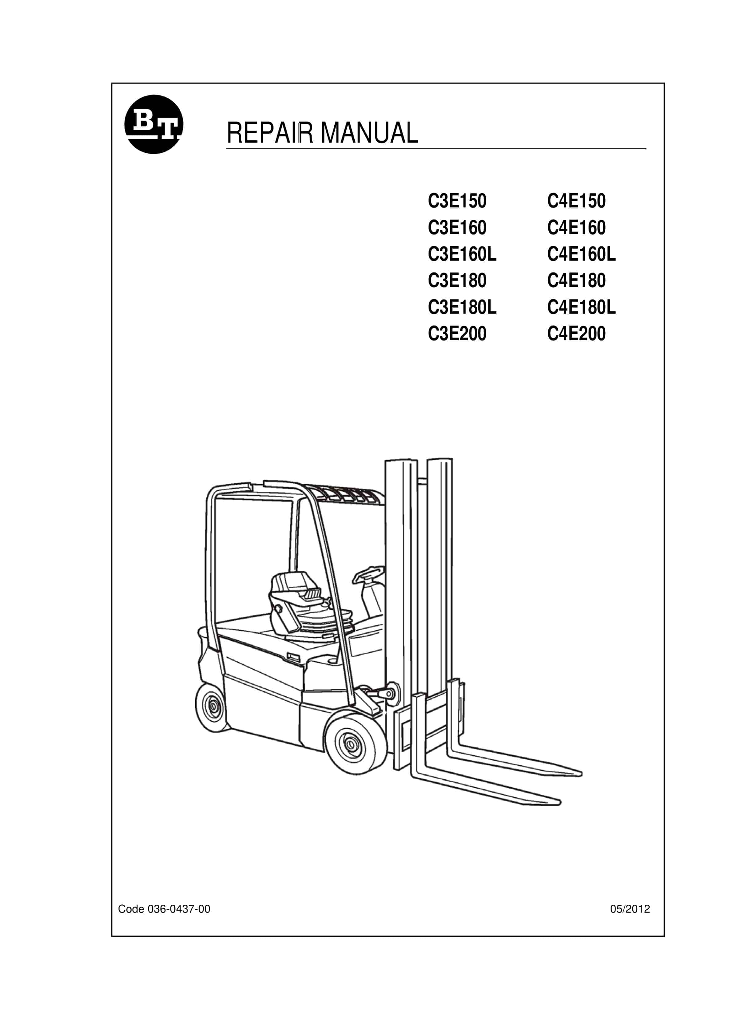
BT C3E150 to C4E200 Repair Manual 036-0437-00
$30.00 Add to cart -
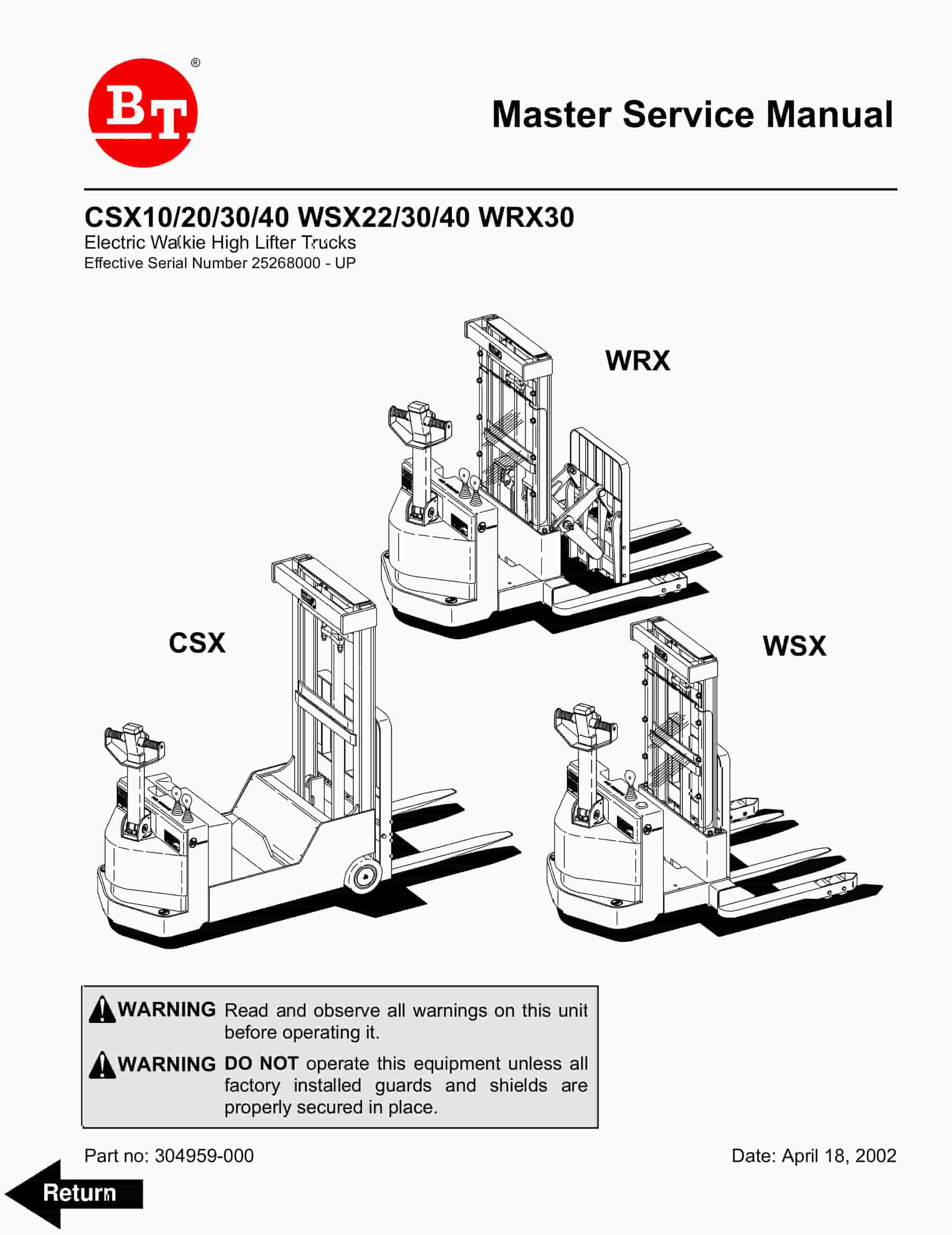
BT CSX10, CSX20, CSX30, CSX40, WSX22, WSX30, WSX40, WRX30 Electric Walkie High Lifter Truck Service Manual 304959-000
$30.00 Add to cart


