

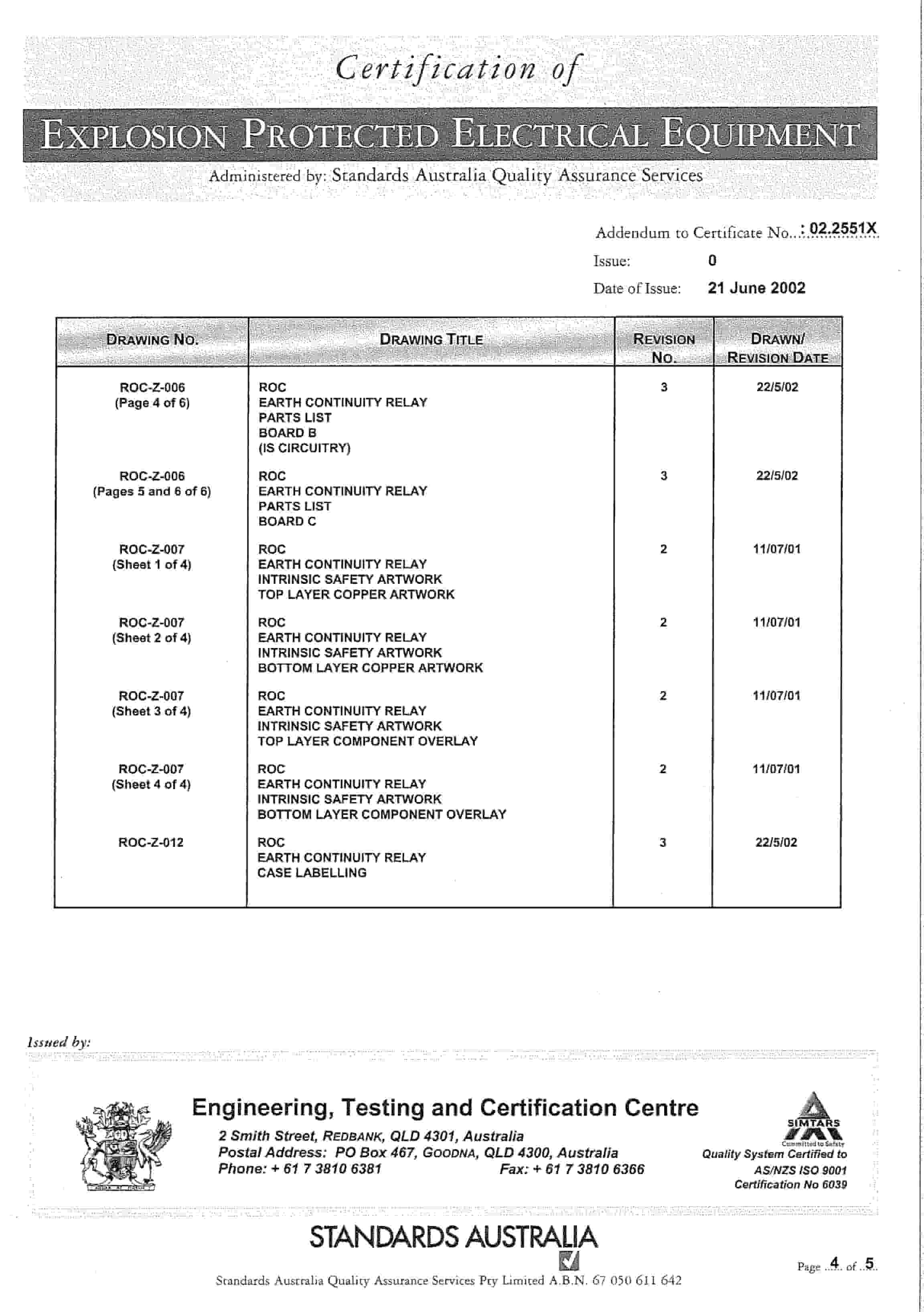
Bucyrus 1140V FLP Starter Operation Manual
$30.00
- Type Of Manual: Operation Manual
- Number of Pages: 286
- Size: 28.9MB
- Format: PDF
Product details
-
Model List:
- 1140V FLP Starter
- 1. Section 1
- 1.1. Starter Operation Manual.pdf
- 1.1.1. Unloading
- 1.1.2. Main Circuit Breaker Not Closing.
- 1.1.3. Outlets Not Closing.
- 1.1.4. BUCYRUS CHINA
- 1.1.5. FLP STARTER
- 1.1.6. P/O No. 4500797579
- 1.1.7. General
- 1.1.8. After isolation of supply, check that power is removed.
- 1.1.9. Working in 1140V Isolator Compartment
- 1.1.10. The 1140V isolator compartment CANNOT be isolated locally from the STARTER.
- 1.1.11. To isolate this compartment authorised personnel need to follow mine isolation procedures and isolate outbye at the equipment supplying the 1140V supply to this unit.
- 1.1.12. Working in 1140V Main Outlet Compartment
- 1.1.13. The 1140V Main Outlet compartment is mechanically interlocked with the main circuit breaker.
- 1.1.14. The door is interlocked to ensure that the isolation procedure is followed correctly.
- 1.1.15. o Turn off Main Circuit Breaker and remove handle This turns off the 1140V Supply and removes the 110V control supply in the main outlet compartment.
- 1.1.16. o Install handle into main outlet compartment lock
- 1.1.17. o Turn handle to undo door interlocking
- 1.1.18. o Remove door bolts and open door NOTE doors are spring loaded and will open slightly when the interlocking and door bolts are removed.
- 1.1.19. Working in 110V PLC Chamber
- 1.1.20. The 110V PLC compartment is mechanically interlocked with the main circuit breaker.
- 1.1.21. The door is interlocked to ensure that the isolation procedure is followed correctly.
- 1.1.22. o Turn off Main Circuit Breaker and remove handle This turns off the 1140V Supply to the outgoing outlets and removes the 110V control supply in the PLC Compartment.
- 1.1.23. o Install handle into PLC compartment lock
- 1.1.24. o Remove door bolts, turn handle to open door
- 1.1.25. Working in IS Remote Display Chamber
- 1.1.26. o The STARTER should be fully isolated before accessing the RDM chamber
- 1.1.27. Working in IS J-Box
- 1.1.28. Working on Outlet Cables / Motors
- 1.1.29. o Turn off Main Circuit Breaker and remove handle This turns off the 1140V Supply to the outgoing outlets and removes the 110V control supply.
- 1.1.30. o Jack out Cable Plug from receptacle and fit personal danger padlock or danger tag as per the mine requirements.
- 1.1.31. o Discharge any stored charge in the cable, motor windings
- 1.1.32. o Test for Dead
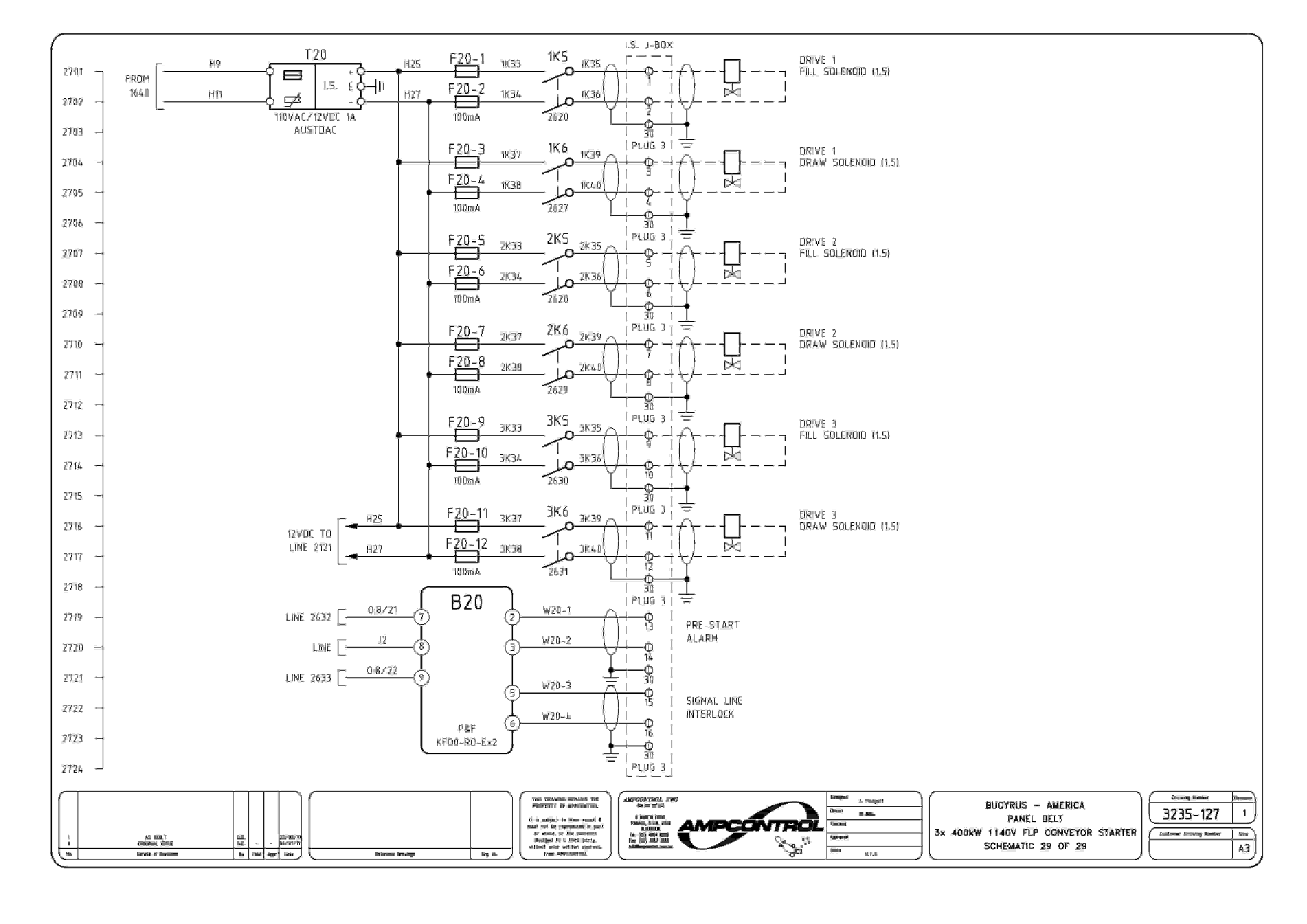
- 1.1.33. Only Schematics thought to need clarification are mentioned.
- 2. Section 2
- 2.1. General Safety
- 3. Section 3
- 4. Section 4.1
- 5. Section 4.2
- 5.1.
- 5.2.
- 6. Section 4.3a
- 7. Section 4.3b
- 8. Section 5
- 9. Section 6
- 10. Section 7
- 10.1. KFD2-SR2-EX2.2S.pdf
- 11. Section 8
- 11.1. ineffective plug earthing
- 11.2. defective bak-bak couplers
- 11.3. electric shock arcing from ineffective arcing
- 11.4. unsafe enclosure overhaul aux fan
- 11.5. serious electric shock incident
- 11.6. failure flp thread repairs
- 11.7. electric shock from cbreaker
- 12. Section 9.0
- 12.1. Certificate Approvals Index.pdf
- 13. Section 9.1
- 14. Section 9.3
- 14.1. IECEx TSA 07.0037U issue 0.pdf
- 14.1.1. COC TSA 07.0037U
- 14.1.2. AF-C-2001 r7
- 14.1.3. AF-C-2002 r2
- 15. Section 9.4
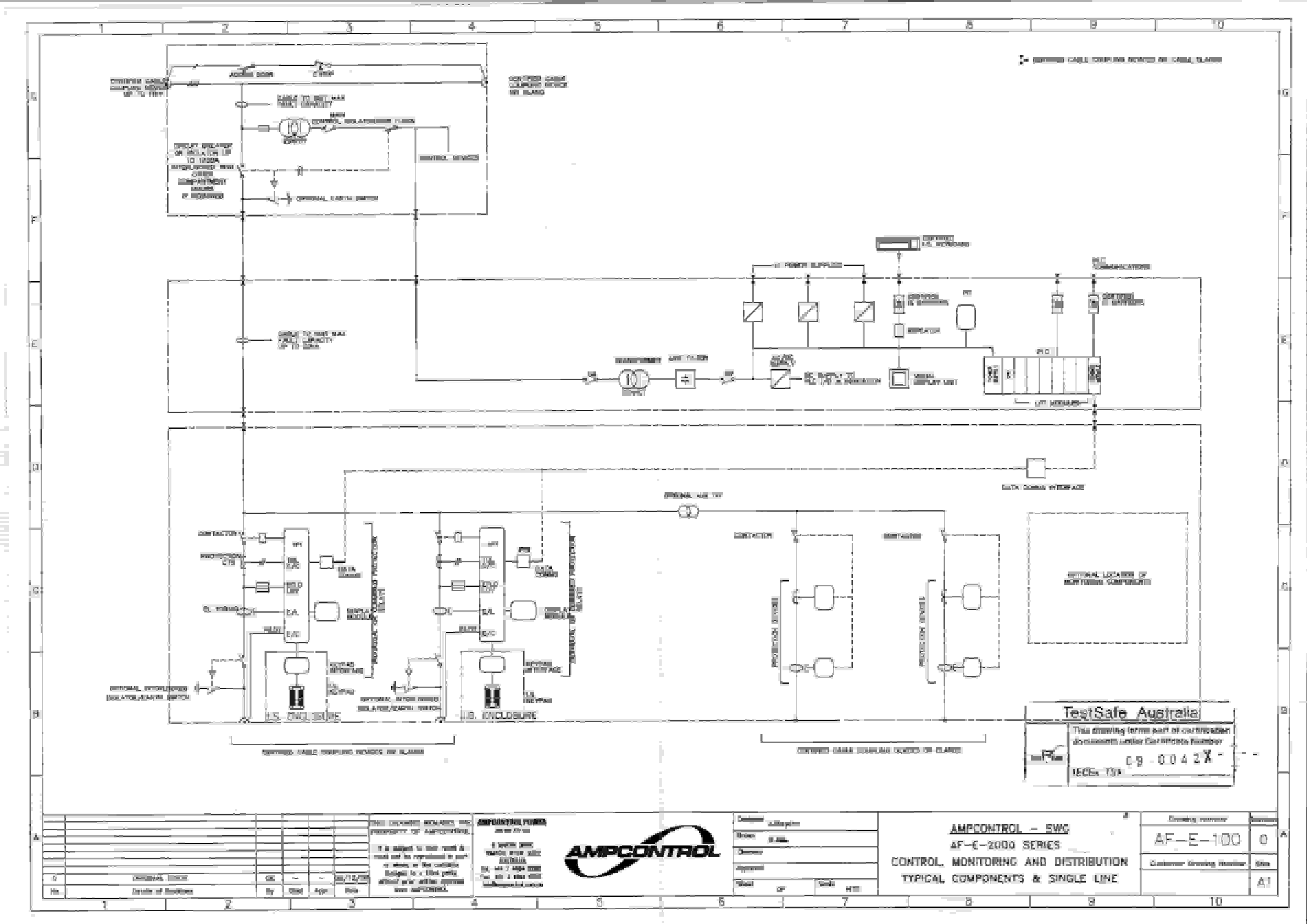
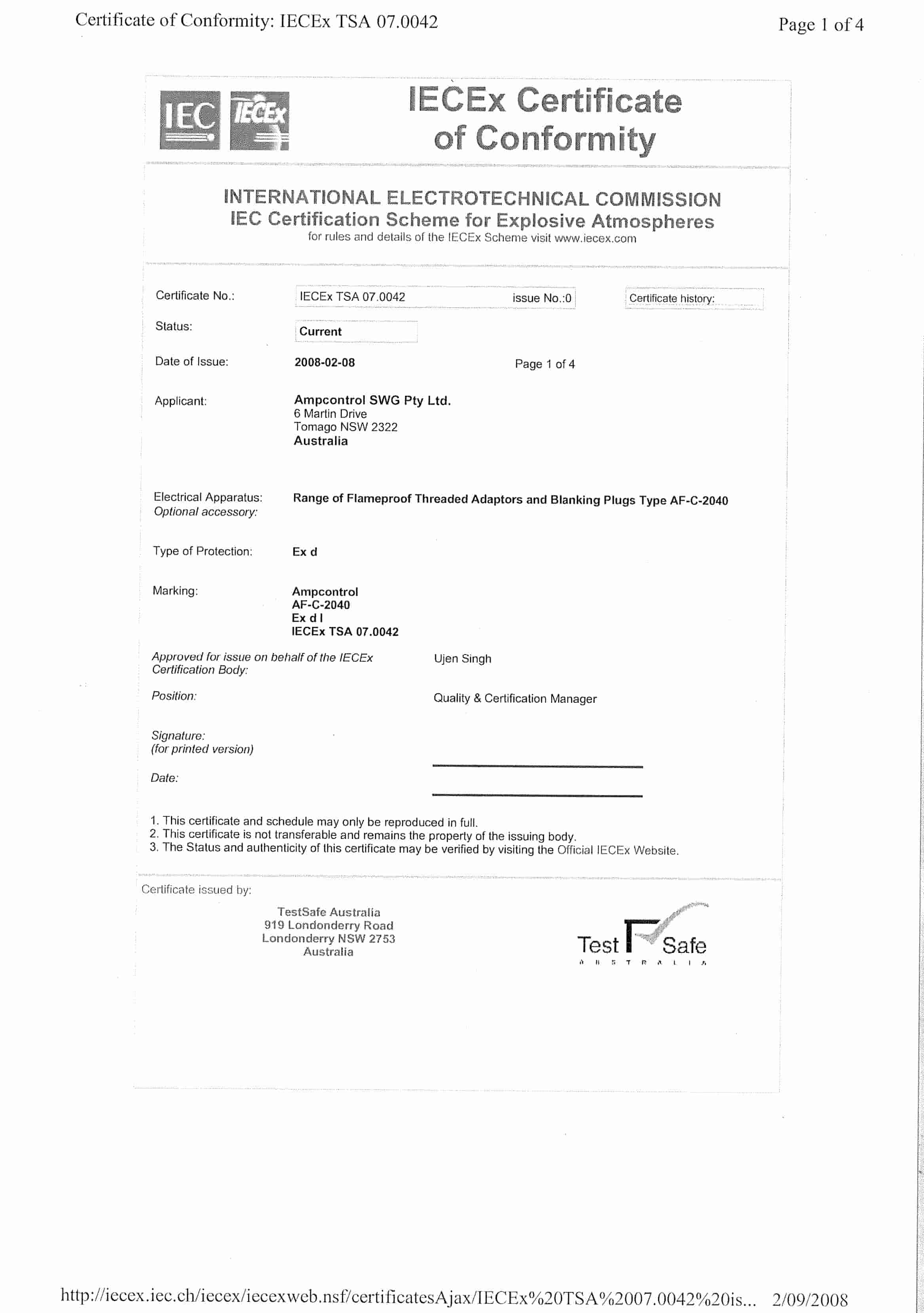
- 15.1. IECEx TSA 07.0042 drwg.pdf
- 15.1.1. IECEx TSA 07.0042 FLPAdaptors Reducers
- 15.1.2. AF_C_2040
- 16. Section 9.6
- 17. Section 9.7
- 18. Section 9.8
- 19. Section 9.9
- 19.1. AUSEx_2524 CoC.pdf
- 19.1.1. REC AUS Ex 2524
- 19.1.2. F-299 Rev I 660-1.1kV 425A RCPT
- 19.1.3. F-367 Rev F 1100-660V 300A RCPT
- 19.1.4. F438 Rev H 1.1-660V 300A QR RCPT Assembly
- 19.1.5. F-447 Rev F 660-1.1kV 425A QR RCPT
- 20. Section 9.10
- 21. Section 9.11
- 21.1. ANZEx 07.3024 CoC.pdf
- 21.1.1. ANZEx 07_3024 FLP Glands
- 21.1.2. ANZEx 07_3024 Glands Drawings
- 21.1.2.1. FWPM rev C (FWPM Gland assembly)
- 21.1.2.2. GWPM GWP rev F (GWPM GWP Gland assembly)
- 21.1.2.3. GWPMGWPASS rev B (GWPMSS GWPSS Gland assembly)
- 22. Section 9.12
- 22.1. IECEx PTB 05.0019.pdf
- 22.2. MDA 10175.pdf
- 22.2.1. Zertifikat (4 Seiten)
Related products
-
Bucyrus 151-M Technical Manual BI005612
$30.00 Add to cart -
Bucyrus 1570W Dragline Technical Manual BI005401
$30.00 Add to cart -
Bucyrus 1370W Walking Dragline Technical Manual BI005556
$30.00 Add to cart -
Bucyrus 1570W Technical Manual BI005406
$30.00 Add to cart -
Bucyrus 1260W Walking Dragline Technical Manual BI005568
$30.00 Add to cart


