


Bucyrus 30MB3 Technical Manual BI620062
$30.00
- Type Of Manual: Technical Manual
- Manual ID: BI620062
- Number of Pages: 213
- Size: 11.4MB
- Format: PDF
Product details
-
Model List:
- 30MB3
- 1. M01295.pdf
- 1.1. Contents Page – Technical Manual
- 1.2. Section 01 Machine Description
- 1.3. Section 02 Defects,Hazards and Safety
- 1.3.1. DEFECTS AND HAZARDS
- 1.3.2. SAFETY MAINTENANCE PRACTICES
- 1.3.3. ULAN PROCEDURES
- 1.3.4. Remote Control Operations Continuous Miner
- 1.3.5. MINE SAFETY MANAGEMENT SYSTEM
- 1.3.5.1. ENERGY CONTROL ISOLATION MANAGEMENT PLAN
- 1.3.5.2. Appendix A Generic 12 Step Isolation Procedures
- 1.3.5.3. HEAD STOPS
- 1.3.5.4. CONVEYOR STOP
- 1.4. Section 03 Isolators Push buttons Switches
- 1.4.1. CIRCUIT BREAKERS – ISOLATORS
- 1.4.1.1. Main Circuit Breaker
- 1.4.1.2. Cutter Circuit Breaker
- 1.4.1.3. Pump – Traction Circuit Breaker
- 1.4.1.4. Conveyor Circuit Breaker
- 1.4.1.5. Control and Light Circuit Breakers
- 1.4.1.6. Traction AC Circuit Breakers
- 1.4.2. PUSH BUTTONS
- 1.4.2.1. Control E/L Test
- 1.4.2.2. Traction Earth Leakage Test
- 1.4.2.3. Traction Earth Leakage Reset
- 1.4.2.4. Screen Scroll – Optional
- 1.4.2.5. Radio Pendant Selector
- 1.4.2.6. CH4 Selector
- 1.4.2.7. Diode Selector
- 1.4.3. MACHINE EMERGENCY STOPS
- 1.4.3.1. Lanyard Machine Emergency Stops
- 1.4.3.2. Bolting Platform Machine Emergency Stops
- 1.4.4. INDICATOR LEDs
- 1.4.5. MODES OF CONTROL
- 1.4.5.1. Radio / Pendant Mode Switch
- 1.4.5.2. Radio Mode
- 1.4.5.3. Pendant Mode
- 1.4.5.4. Pendant
- 1.4.6. EMERGENCY SHUTDOWN
- 1.4.6.1. Transmitter Stops
- 1.4.7. EMERGENCY PROCEDURES WHILST OPERATING
- 1.4.7.1. Fire Emergency Procedure
- 1.5. Section 04 General Electrical
- 1.5.1. MACHINE POWER
- 1.5.1.1. Phase Rotation
- 1.5.1.2. Phase Loss
- 1.5.1.3. Machine Supply Voltage Indication
- 1.5.2. PILOT CIRCUIT
- 1.5.2.1. Pilot Buffer Relay
- 1.5.2.2. Pilot Tripping
- 1.5.2.3. Radio Watchdog Trip
- 1.5.2.4. Radio Emergency Stop Trip
- 1.5.2.5. The Diode
- 1.5.3. POWER CIRCUIT
- 1.5.4. CONTROL CIRCUIT
- 1.5.4.1. Control Circuit Supply
- 1.5.4.2. Phase 110V Machine Supply Monitoring
- 1.5.4.3. Machine Control Supply Voltage
- 1.5.4.4. Volt Lighting
- 1.5.4.5. DC Power Supply PS1
- 1.6. Section 05 Electrical Component Layouts
- 1.6.1. Main Control Case
- 1.6.1.1. Rear Wall
- 1.6.1.2. Right Side Wall Top
- 1.6.1.3. Right Side Wall Lower
- 1.6.1.4. Left Side Wall
- 1.6.1.5. Swing Panel Rear
- 1.6.2. Display Enclosure
- 1.6.2.1. Isolator Compartment
- 1.6.2.2. DISPLAY COMPARTMENT
- 1.6.2.2.1. Rear Wall
- 1.6.2.2.2. Front Swing Panel
- 1.6.2.3. SOLENOID MODULE JUNCTION BOX
- 1.6.2.3.1. Rear Wall
- 1.6.2.3.2. Door Panel
- 1.6.2.3.3. Main Control Case
- 1.6.2.3.4. Display Enclosure
- 1.7. Section 06 Radio Remote Control System
- 1.7.1. RADIO REMOTE CONTROL SYSTEM
- 1.7.1.1. Description
- 1.7.1.2. System Components
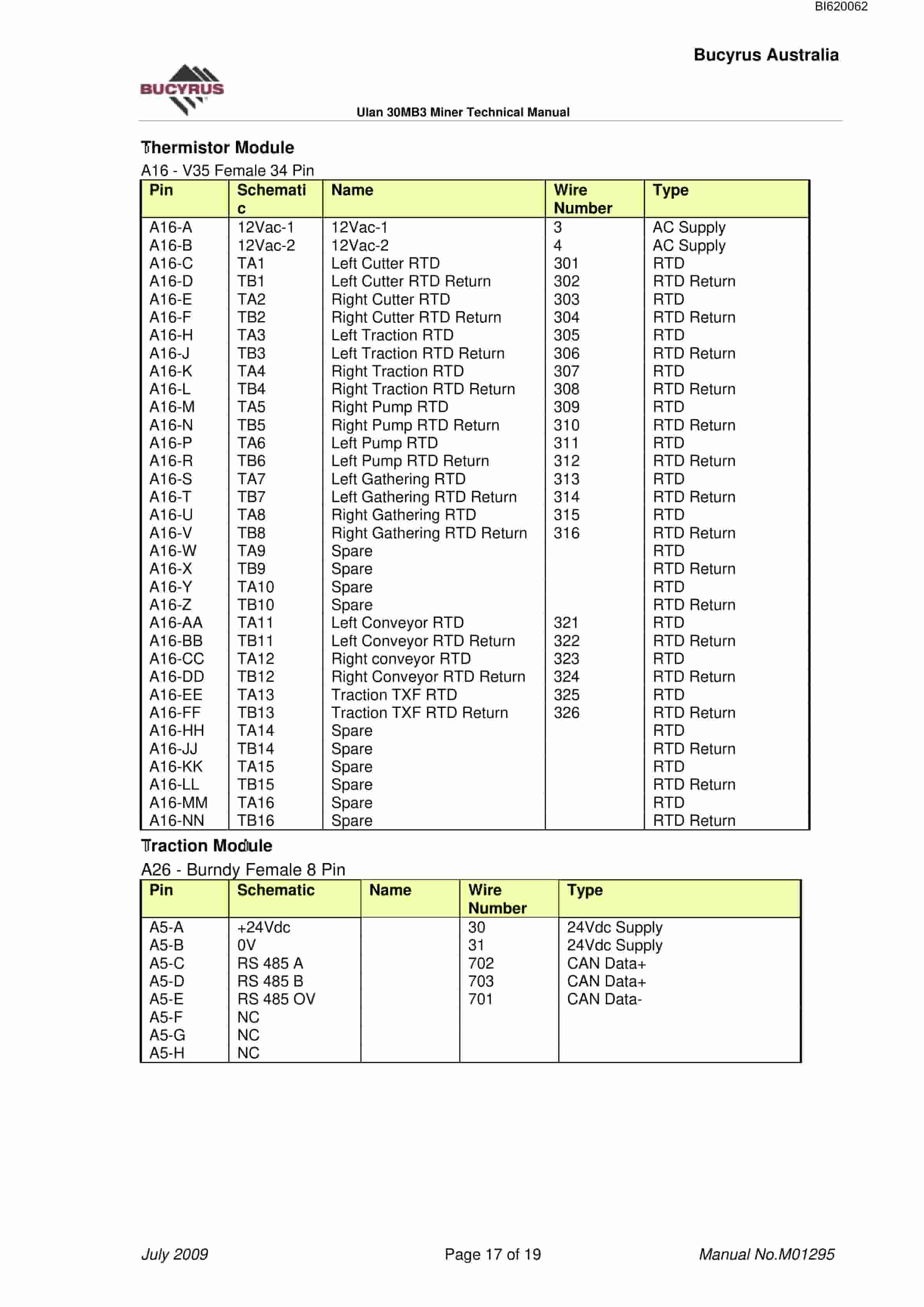
- 1.7.1.3. Thermistor Module
- 1.7.1.4. Power Supply Module
- 1.7.1.5. Inclinometer
- 1.7.1.6. Traction Module
- 1.7.1.7. Graphics Display Screen
- 1.7.1.8. Solenoid Module
- 1.7.1.9. Control Area Network (CAN)
- 1.7.1.10. CAN Cable
- 1.7.2. CONTROL SYSTEM FUNCTIONALITY
- 1.7.2.1. Network
- 1.7.2.2. Features
- 1.7.3. MODULE PIN ALLOCATIONS
- 1.7.3.1. Processor Control Hub
- 1.7.3.1.1. Antenna (UHF)
- 1.7.3.1.2. Programming RS232
- 1.7.3.1.3. Supply /CAN A
- 1.7.3.1.4. Hub CAN B / Digital Inputs
- 1.7.3.2. Relay I/O Module A
- 1.7.3.2.1. Analogue Digital Inputs
- 1.7.3.2.2. Relay Outputs
- 1.7.3.3. Relay I/O Module B
- 1.7.3.3.1. Analogue Digital Inputs
- 1.7.3.3.2. Relay Outputs
- 1.7.3.4. Solenoid Module
- 1.7.3.4.1. dc I.S Solenoid Board
- 1.7.3.4.2. dc I.S. Proximity Input Board
- 1.7.3.4.3. dc I.S. Digital Input Board
- 1.7.3.5. Thermistor Module
- 1.7.3.6. Traction Module
- 1.7.3.7. Power Supply Module
- 1.7.3.7.1. dc Output CAN
- 1.7.3.7.2. Supply Relay Outputs
- 1.7.4. COMPONENT OVERVIEW
- 1.8. Section 07 Graphics Display Screens
- 1.8.1. GRAPHIC DISPLAY SCREENS
- 1.8.1.1. Navigation Functions on Transmitter
- 1.8.1.2. Main Monitor Screen
- 1.8.1.3. Production Monitor Screen No 1
- 1.8.1.4. Production Monitor Screen No 2 Boom Monitor
- 1.8.1.5. Pump Monitor
- 1.8.1.6. Cutter Monitor
- 1.8.1.7. Conveyor Monitor E/W Machine only
- 1.8.1.8. Gathering Monitor Not Used on E/W Machine
- 1.8.1.9. Traction Monitor
- 1.8.1.10. Transformer Monitor
- 1.8.1.11. I/O Monitor Inputs 1 of 5 (110V Inputs)
- 1.8.1.12. I/O Monitor Inputs 2 of 5 (I.S. Inputs)
- 1.8.1.13. I/O Monitor Inputs 3 of 5 (Module A Analogues)
- 1.8.1.14. I/O Monitor Inputs 4 of 5 (Module B Analogues)
- 1.8.1.15. I/O Monitor Inputs 5 of 5 (I.S. Proximity)
- 1.8.1.16. I/O Monitor Outputs 1 of 2 (110V I/O Modules A B)
- 1.8.1.17. I/O Monitor Outputs 2 of 2 (12V I.S. Solenoids)
- 1.8.1.18. I/O Monitor PT100s (Thermistors)
- 1.8.1.19. CAN and TEMP Monitor
- 1.8.1.20. SOFTWARE Monitor
- 1.8.1.21. SCR Drive Monitor
- 1.8.1.22. Event Monitor
- 1.8.1.23. Fault Log Information Inside Event Monitor
- 1.8.1.24. Setup Left Traction
- 1.8.1.25. Setup Right Traction
- 1.8.1.26. Setup 1 of 10 Timers
- 1.8.1.27. Setup 2 of 10 – Configuration
- 1.8.1.28. Setup 3 of 10 Sump Currents
- 1.8.1.29. Setup 4 of 10 Passwords
- 1.8.1.30. Setup 5 of 10 Inclinometer
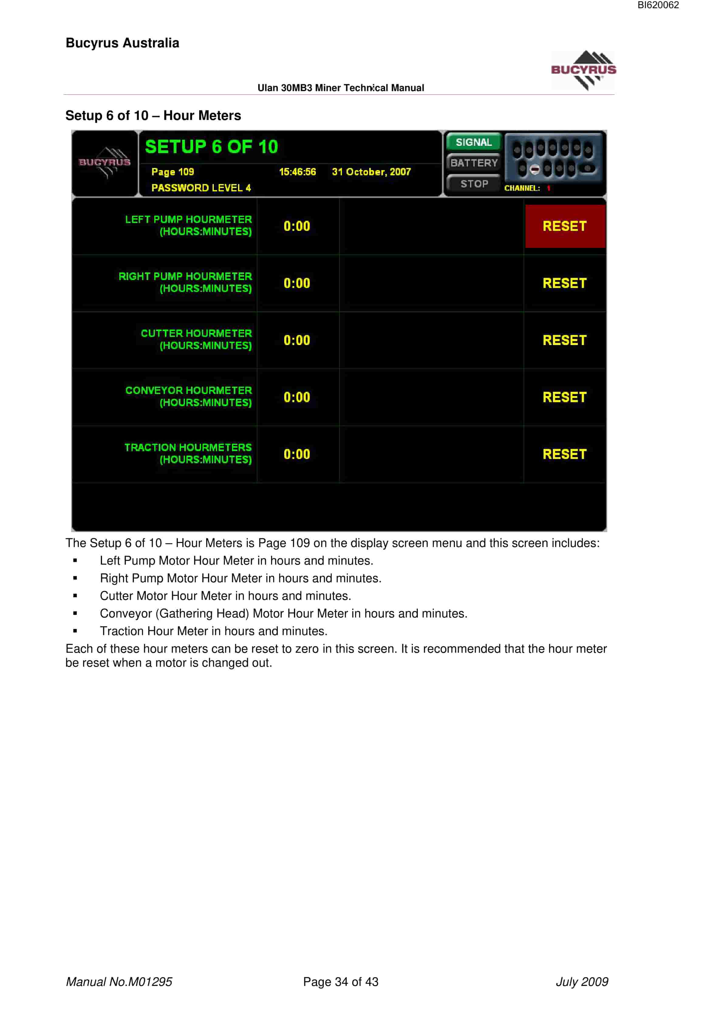
- 1.8.1.31. Setup 6 of 10 Hour Meters
- 1.8.1.32. Setup 7 of 10 Motor Overloads
- 1.8.1.33. Setup – Time Date
- 1.8.1.34. Test – Radio
- 1.8.1.35. Test Solenoids
- 1.8.1.36. Password Levels and Access
- 1.8.1.37. Parameters Default
- 1.8.1.38. Parameters Changed 3-11-2007
- 1.9. Section 08 Electrical Schematics
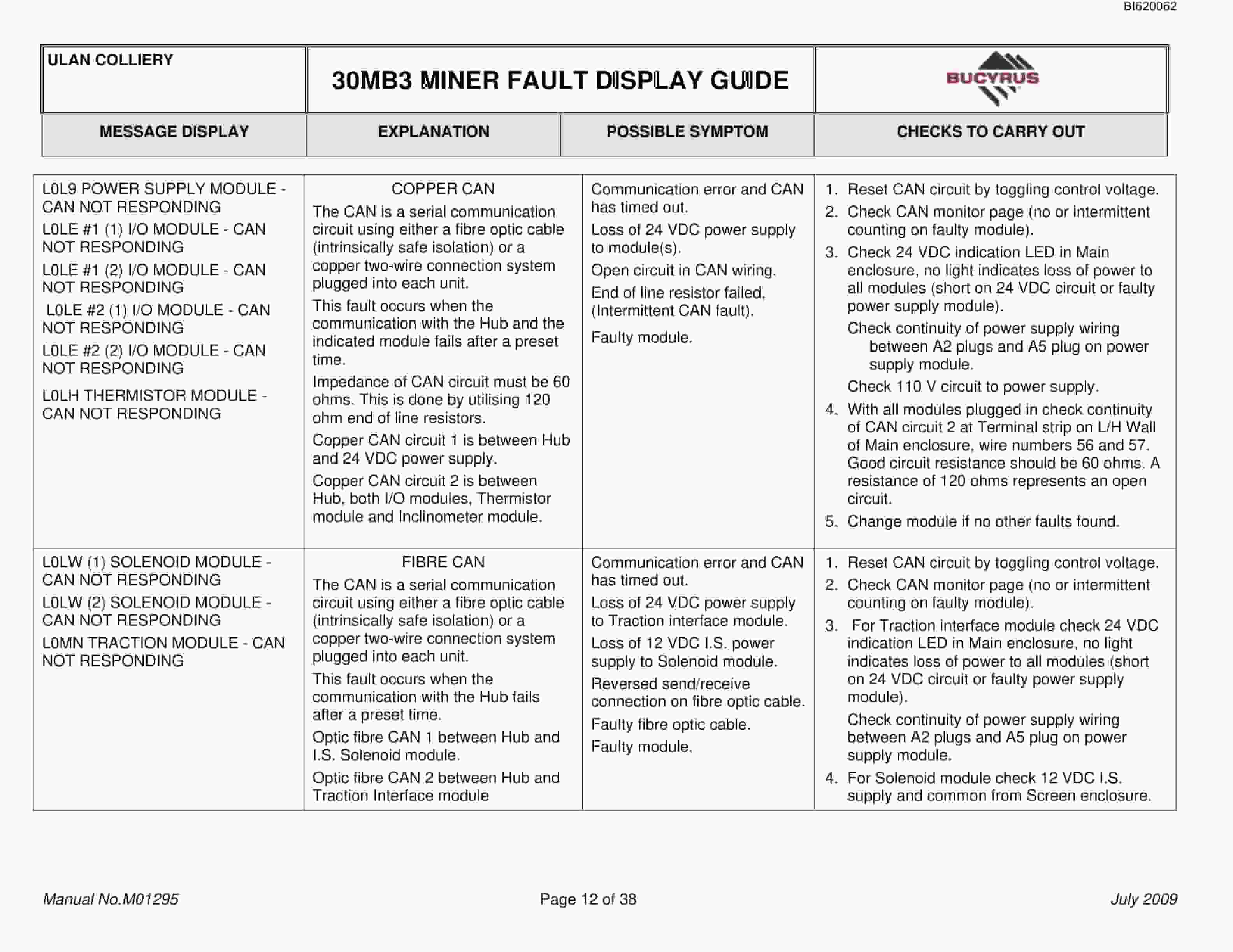
- 1.10. Section 09 Troubleshooting
- 1.10.1. A RS 485 half duplex 3 wire serial link is used to communicate between the Traction interface module and the traction drives.
- 1.10.2. This input is active when the hydraulic oil level is above the oil warning float (top float).
- 1.10.3. Proximity Switch Install / Adjust Procedure
- 1.11. Section 10 Remote control transmitter
- 1.11.1. REMOTE CONTROL TRANSMITTER
- 1.11.1.1. Description
- 1.11.1.2. Radio Signal Continuity
- 1.11.1.3. Turning On
- 1.11.1.4. Turning Off
- 1.11.1.5. Pilot Trip
- 1.11.1.6. Start Pumps
- 1.11.1.7. Stop Pumps
- 1.11.1.8. Raise Cutter
- 1.11.1.9. Lower Cutter
- 1.11.1.10. Conveyor Up
- 1.11.1.11. Conveyor Down
- 1.11.1.12. Conveyor Left
- 1.11.1.13. Conveyor Right
- 1.11.1.14. Apron Float
- 1.11.1.14.1. Toggle and hold the APRON FLOAT switch to lower the apron.
- 1.11.1.15. Apron Up
- 1.11.1.16. Lower Stabiliser
- 1.11.1.17. Raise Stabiliser
- 1.11.1.18. Cutters
- 1.11.1.19. Start Cutters
- 1.11.1.20. Stop Cutters
- 1.11.1.21. Tramming
- 1.11.1.22. Gathering Heads Conveyor
- 1.11.1.23. Conveyor Forward
- 1.11.1.24. Conveyor Reverse
- 1.11.1.25. Conveyor Stop
- 1.11.2. Battery Charger
- 1.11.3. Remote Control Battery Charger
- 1.11.4. Remote Control Diagnostics
- 1.11.5. User Setup
- 1.11.5.1. Password Entry
- 1.11.5.2. Radio Channel
- 1.11.5.3. Radio Timeout
- 1.11.5.4. Tilt Switch
- 1.11.5.5. ID Number
- 1.11.5.6. Saving Changes
- 1.11.5.7. Inspection Frequency
- 1.11.5.8. Factory Service Frequency
- 1.11.5.9. Disassembly
- 1.11.5.10. Cleaning
- 1.11.5.11. Reassembly
Related products
-
Bucyrus Gleithobel Plow Outrigger Steering System Technical Description 1999 001 027 BA 00
$30.00 Add to cart -
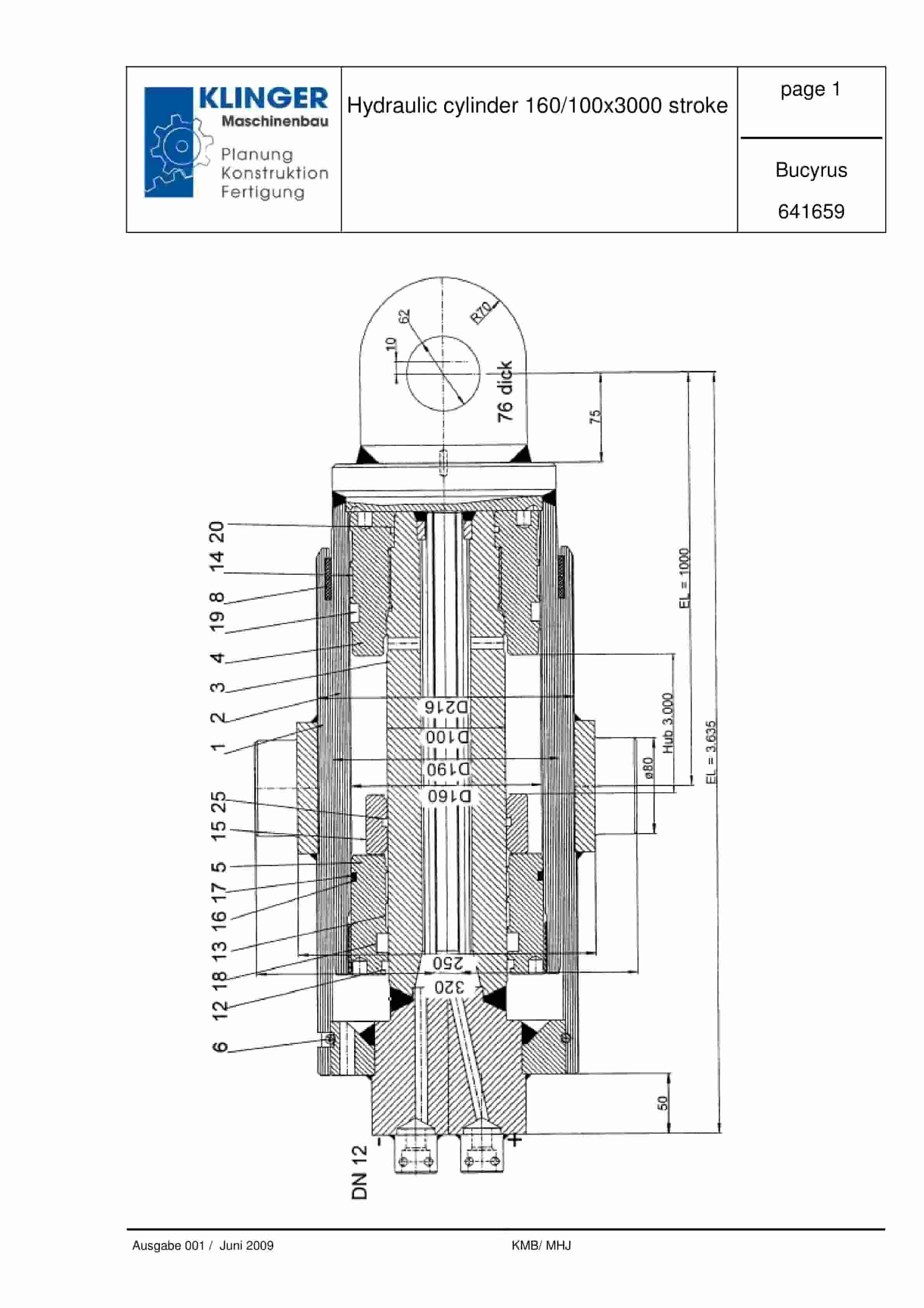
Bucyrus Hydraulic Cylinder 160-100 x 3000 Stroke Service Parts List 641659
$30.00 Add to cart -
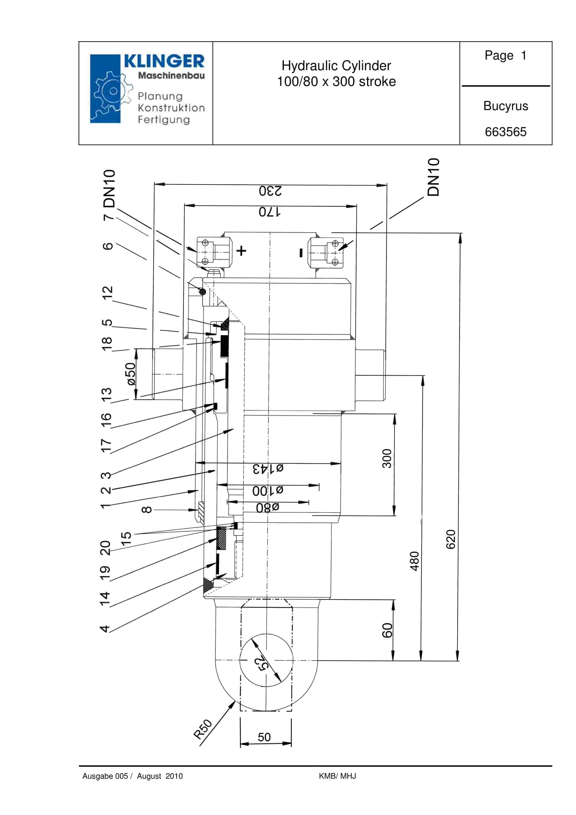
Bucyrus Hydraulic Cylinder 100-80 x 300 Stroke Service Parts List 663565
$30.00 Add to cart -
Bucyrus Continuous Miner Spare Parts List 373608
$30.00 Add to cart -
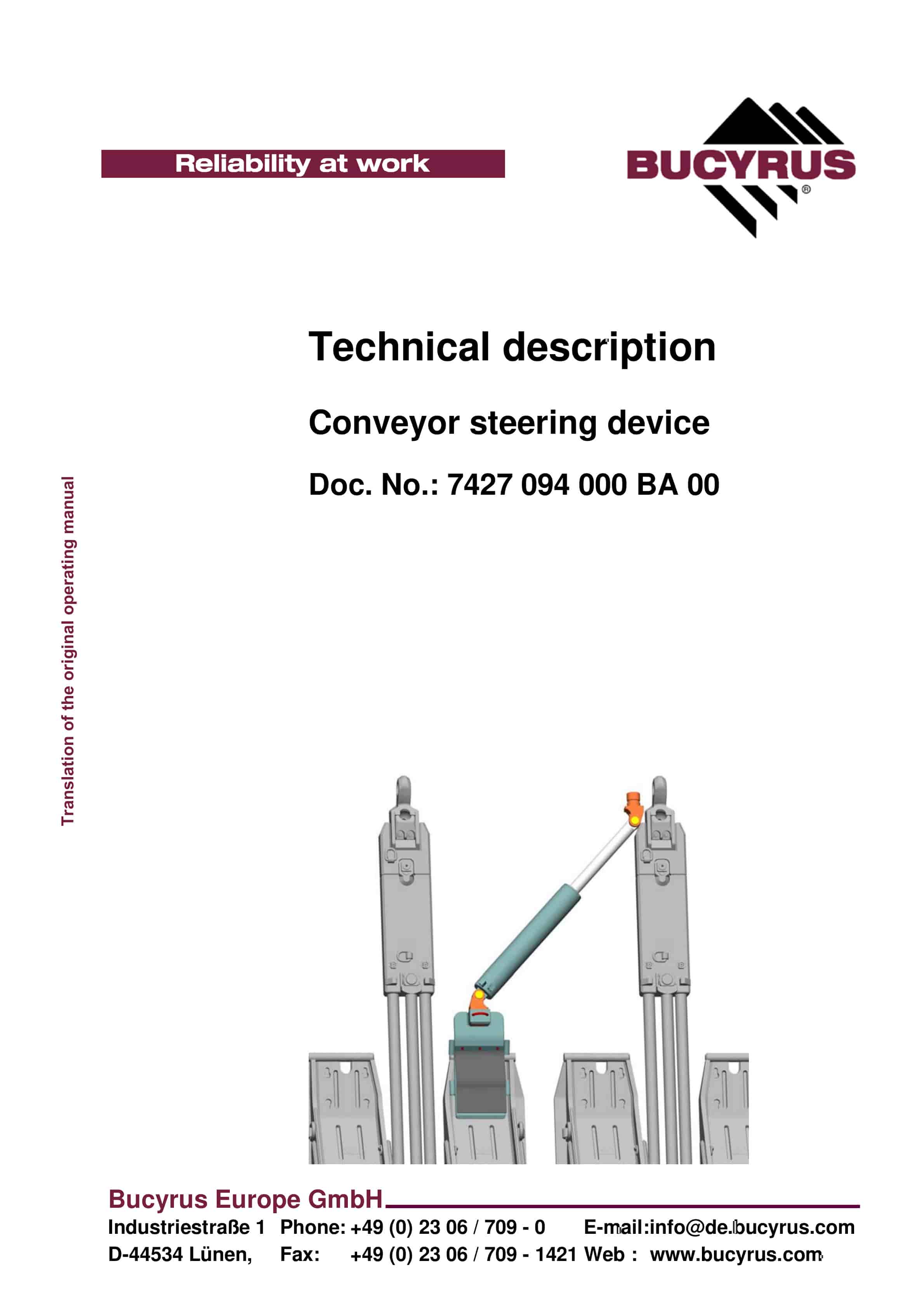
Bucyrus Conveyor Steering Device Technical Description 7427 094 000 BA 00
$30.00 Add to cart


