


Bucyrus 30MB3 Technical Manual BI620137
$30.00
- Type Of Manual: Technical Manual
- Manual ID: BI620137
- Number of Pages: 234
- Size: 8.8MB
- Format: PDF
Product details
-
Model List:
- 30MB3
- 1. M01404.pdf
- 1.1. Machine Description 30MB3
- 1.1.1. General
- 1.1.2. Specifications
- 1.1.3. Machine Weights
- 1.2. Component Layout
- 1.2.1. Top View
- 1.2.2. Right Hand View
- 1.2.3. Left Hand View
- 1.2.4. Main Chassis
- 1.2.5. Cutting Head Assembly
- 1.2.6. Gathering Head Assembly
- 1.2.7. Conveyor Assembly
- 1.2.8. Traction Drive System
- 1.2.9. Hydraulic System – CLA
- 1.2.10. Machine Hydraulic Layout
- 1.2.11. Drill Rigs
- 1.2.12. Rib Protection
- 1.2.13. Articulating Temporary Roof Support – ATRS
- 1.2.14. Bolting, Mining and Maintenance Modes
- 1.2.15. Water System
- 1.2.16. Machine Water Component Layout
- 1.3. Defects and Hazards
- 1.4. Safety Maintenance Practices
- 1.4.1. Safety Procedures
- 1.4.2. Isolation Procedures
- 1.5. Auger Safety Stops
- 1.6. Conveyor Stop
- 1.7. General Maintenance
- 1.7.1. Maintenance and the Continuous Miner
- 1.8. Torques
- 1.8.1. Duo-Cone Seals
- 1.8.2. Mating Pairs
- 1.8.3. Handling
- 1.8.4. Housing Preparation
- 1.8.5. Seal Preparation
- 1.8.6. Approved Assembly Lubricants
- 1.8.7. Installation Process
- 1.8.8. Final Assembly
- 1.9. Maintenance Guidelines
- 1.10. Bearing and Gears
- 1.10.1. Bearing Assembly Methods
- 1.10.2. Assembly Methods
- 1.10.3. Micronized Graphite for Bearing Assembly
- 1.10.4. Drivers for Bearing Cups and Cones
- 1.10.5. Heating Bearings
- 1.10.6. Heating in Oil
- 1.10.7. Induction Heating
- 1.10.8. Freezing/Shrinking Bearing Cups
- 1.10.9. Tapered Rolling Bearing Adjustment
- 1.10.10. Thermal Expansion
- 1.10.11. Torque for Zero End Play
- 1.10.12. Bevel Gear Adjustment
- 1.11. Lockwiring Fasteners
- 1.11.1. Single Wire
- 1.11.2. Wired In Pairs
- 1.12. Special Fasteners
- 1.13. Self-Locking Screws
- 1.13.1. Installation Recommendations
- 1.14. Locknuts
- 1.14.1. Installation Recommendations
- 1.15. Component Substitution
- 1.16. Safety Maintenance
- 1.17. General Description
- 1.18. Removal of Cutting Drums
- 1.18.1. Pull In Drum Removal
- 1.18.2. Pull In Drum Assembly
- 1.18.3. Drive Drum Removal
- 1.18.4. Drive Drum Assembly
- 1.18.5. Intermediate Drum Removal RH and LH
- 1.18.5.1. Intermediate Drum Removal RH
- 1.19. Removal of Pull In Assembly Complete
- 1.20. Intermediate Drum Removal LH
- 1.20.1. Intermediate Drum Assembly RH and LH
- 1.20.2. Install Complete Pull In Assembly
- 1.20.3. Centre Drum Removal
- 1.20.4. Centre Drum Assembly
- 1.21. Removal of Cutting Motor Clutches
- 1.21.1. Clutch Assembly
- 1.21.2. Removal of Cutter Head Gear Case
- 1.21.3. Reinstall Cutter Head Gear Case
- 1.21.4. Removal of Cutter Motor
- 1.21.5. Installation of Cutter Motor
- 1.21.6. Removal of the Cutter Head Input Gear Case
- 1.21.7. Installation of Cutter Head Input Gear Case
- 1.22. Removal of the Cutting Head Support from the Main Frame
- 1.23. Installation of Cutting Head Assembly to the Main Frame
- 1.24. GATHERING HEAD ASSEMBLY
- 1.25. General Description
- 1.26. Removal and Replacing Gathering Head Shear Shaft
- 1.27. Conveyor Chain Disassembly
- 1.28. Removal of Foot Shaft and Centrifugal Loading Arms (CLAs)
- 1.28.1. Removing the Centrifugal Loading Arms (CLAs).
- 1.28.2. Re-Fitting the Centrifugal Loading Arms (CLAs)
- 1.29. Removal of the Drive Motor Input Gear Case and CLA Pot
- 1.30. Reassembly of Gathering Head Gear Cases
- 1.31. Removal of the Gathering Head from the Main Frame
- 1.32. Installation of the Gathering Head
- 1.33. CONVEYOR ASSEMBLY
- 1.34. General Description
- 1.35. Conveyor Chain Removal
- 1.36. Conveyor Chain Installation
- 1.37. Removal of the Conveyor Assembly from the Miner
- 1.38. Installation of the Conveyor Assembly
- 1.39. Removal of Discharge Conveyor
- 1.40. Installation of Discharge Conveyor
- 1.41. Removal of Tail Roller
- 1.41.1. Re-Fitting of Tail Roller
- 1.42. TRACTION SYSTEM
- 1.43. General Description
- 1.44. Removal of the Tram Drive Gear Case Assembly
- 1.45. Installation of the Tram Drive Gear Case Assembly
- 1.46. Removal of a Tram Drive Motor
- 1.47. Installation of a Tram Motor
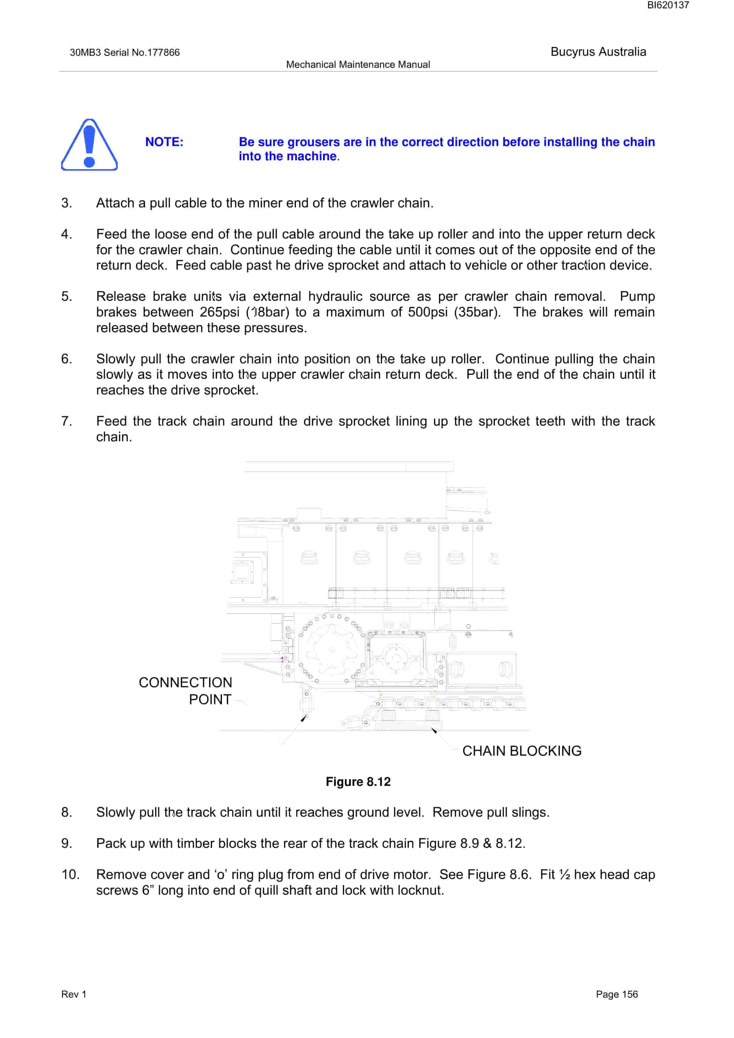
- 1.48. Crawler Chain Removal
- 1.49. Crawler Chain Installation
- 1.50. Crawler Take-Up Roller Removal
- 1.51. Crawler Take-Up Roller Installation
- 1.52. Stablising Shoe Assembly
- 1.52.1. Stabiliser Cylinder Removal
- 1.52.2. Stabiliser Cylinder Installation
- 1.53. Stabiliser Shoe Removal
- 1.54. Cutterhead Raise and Lower Cylinder
- 1.54.1. Cutter Head Cylinder Removal
- 1.54.2. Cutter Head Cylinder Installation
- 1.55. Gathering Head Raise and Lower Cylinder
- 1.55.1. Gathering Head Cylinder Removal
- 1.55.2. Gathering Head Cylinder Installation
- 1.56. Conveyor Raise and Lower Cylinder
- 1.56.1. Conveyor Raise Cylinder Removal
- 1.56.2. Conveyor Raise Cylinder Installation
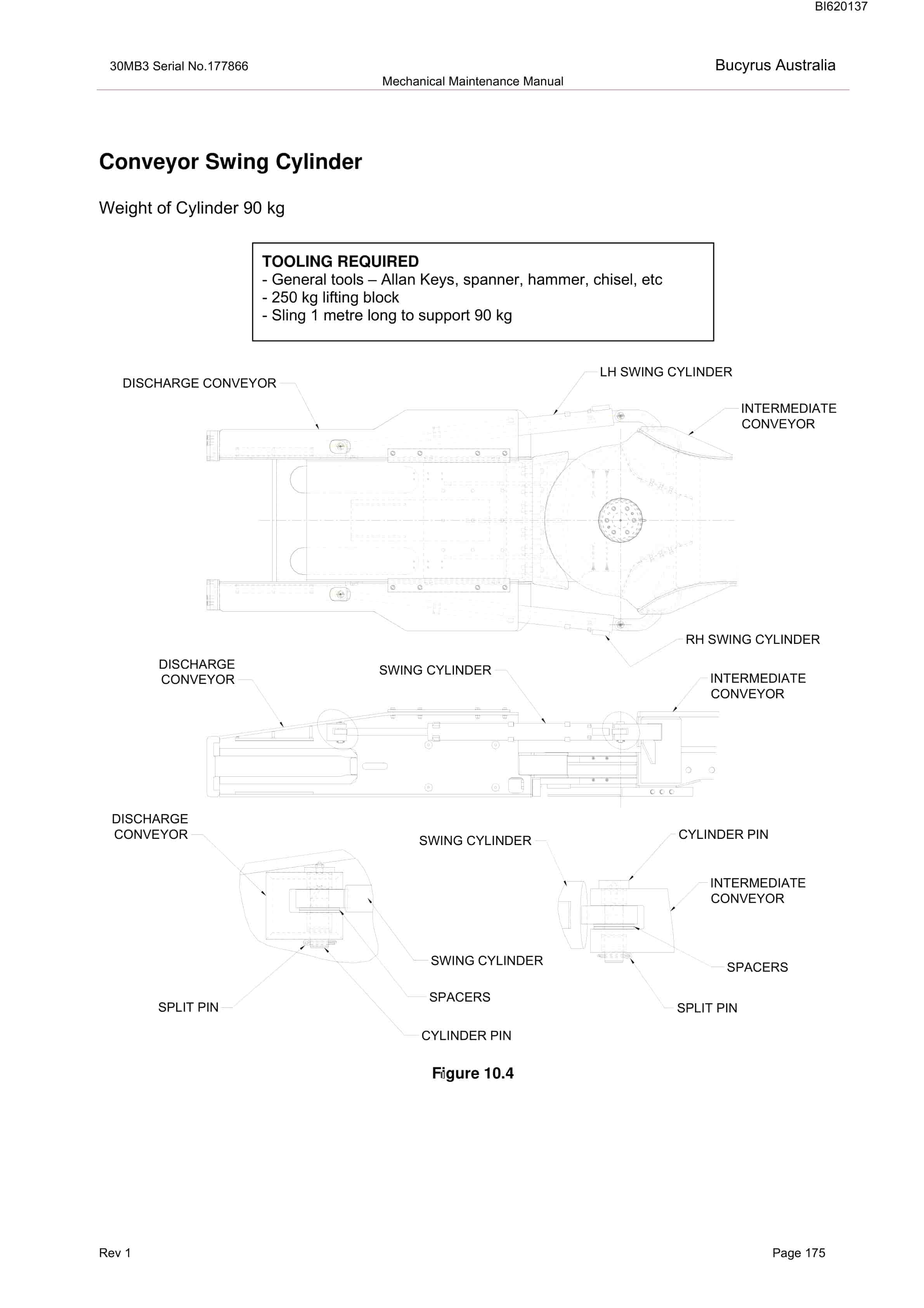
- 1.57. Conveyor Swing Cylinder
- 1.57.1. Conveyor Swing Cylinder Removal
- 1.57.2. Conveyor Swing Cylinder Installation
- 1.58. Plow Cylinders
- 1.58.1. Plow Cylinder Removal
- 1.58.2. Plow Cylinder Installation
- 1.59. Conveyor Take-Up Cylinders
- 1.59.1. Conveyor Take-up Cylinder Removal
- 1.59.2. Conveyor Take-up Cylinder Installation
- 1.60. TRS Raise and Lower Cylinder
- 1.60.1. TRS Cylinder Removal
- 1.61. Servicing and Maintenance
- 1.62. Top View Lubrication
- 1.63. Left Hand Side Lubrication
- 1.64. Right Hand Side Lubrication
- 1.65. Lubrication Chart
- 1.66. Lubrication Gear Oil
- 1.66.1. Tram Gear Cases
- 1.66.1.1. Cutter Head Input Gear Cases
- 1.66.2. Gathering Head (POT) Gear Cases
- 1.66.3. Gathering Head Input Gear Cases
- 1.66.4. Traction Idler Roller
- 1.67. Greasing
- 1.68. Tram Brakes
- 1.69. Filters
- 1.69.1. Left Hand Filters
- 1.69.2. Right Hand Filters
- 1.70. Chain Adjustments
- 1.70.1. Crawler Track Chain Adjustment
- 1.70.2. Conveyor Chain Adjustment
- 1.71. Maintenance Mode
- 1.71.1. Check and Fill Hydraulic Oil Reservoir
- 1.71.2. Hydraulic Oil Power Fill
- 1.71.3. Gear Case Oil Power Fill
- 1.72. Repair or Replace Water Sprays
- 1.73. Machine Cutting Picks
- 1.74. HYDRAULIC COMPONENTS ASSEMBLY
- 1.75. Description
- 1.76. Mechanical
- 1.77. Hydraulic Pump Installation
- 1.78. Removal and Replacement of Pump Drive Motor
- 1.78.1. Pump Drive Motor Removal
- 1.78.2. Pump Drive Motor Installation
- 1.79. Hydraulics
- 1.80. Hydraulic Pump
- 1.80.1. Power Cut Off Control D
- 1.80.2. Load Sensing Control S
- 1.81. Valve Bank Information
- 1.82. Adjustments
- 1.82.1. Conveyor Tension and Tramming Brake Coolant
- 1.82.2. Main Relief Valve (Main valve bank inlet) – OPTIONAL
- 1.83. Water Reticulation
- 1.83.1. General
- 1.83.2. Circuit 1 (Right Side)
- 1.83.3. Circuit 2 (Left Side)
- 1.84. Tramming
- 1.85. Water Sprays
- 1.86. Flow Switches
- 1.87. Traction
- 1.88. Cutters
- 1.89. Conveyor
- 1.90. Event Monitor
- 1.90.1. Fault Log inside Event Monitor
- 1.91. Main Control Case Indicators
- 1.92. Water Troubleshooting Guide
- 1.93. Service
Related products
-
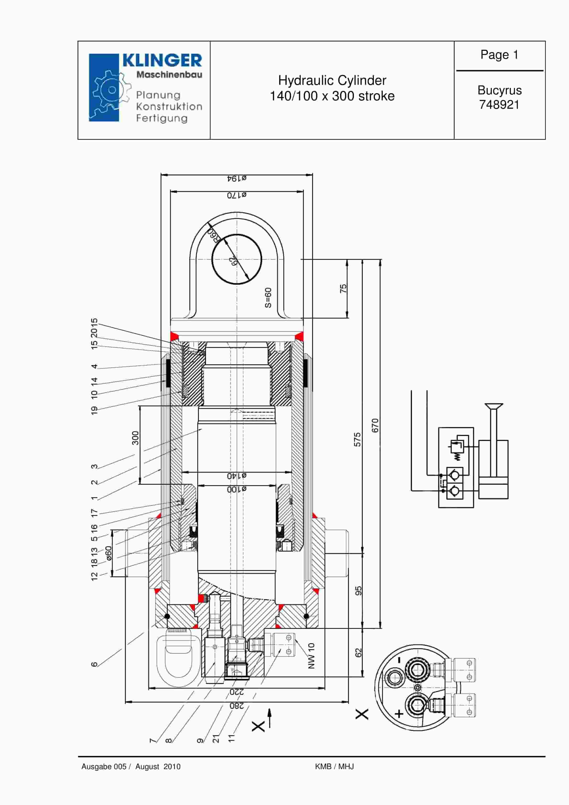
Bucyrus Hydraulic Cylinder 140-100 x 300 Stroke Service Parts List 748921
$30.00 Add to cart -
Bucyrus Continuous Miner Spare Parts List 907781
$30.00 Add to cart -
Bucyrus Gleithobel Plow Outrigger Steering System Technical Description 1999 001 031 BA 00
$30.00 Add to cart -

Bucyrus Fundamentals Of Electrical Engineering Technical Handbook 2440049
$30.00 Add to cart -
Bucyrus Continuous Miner Spare Parts List 907782
$30.00 Add to cart


