

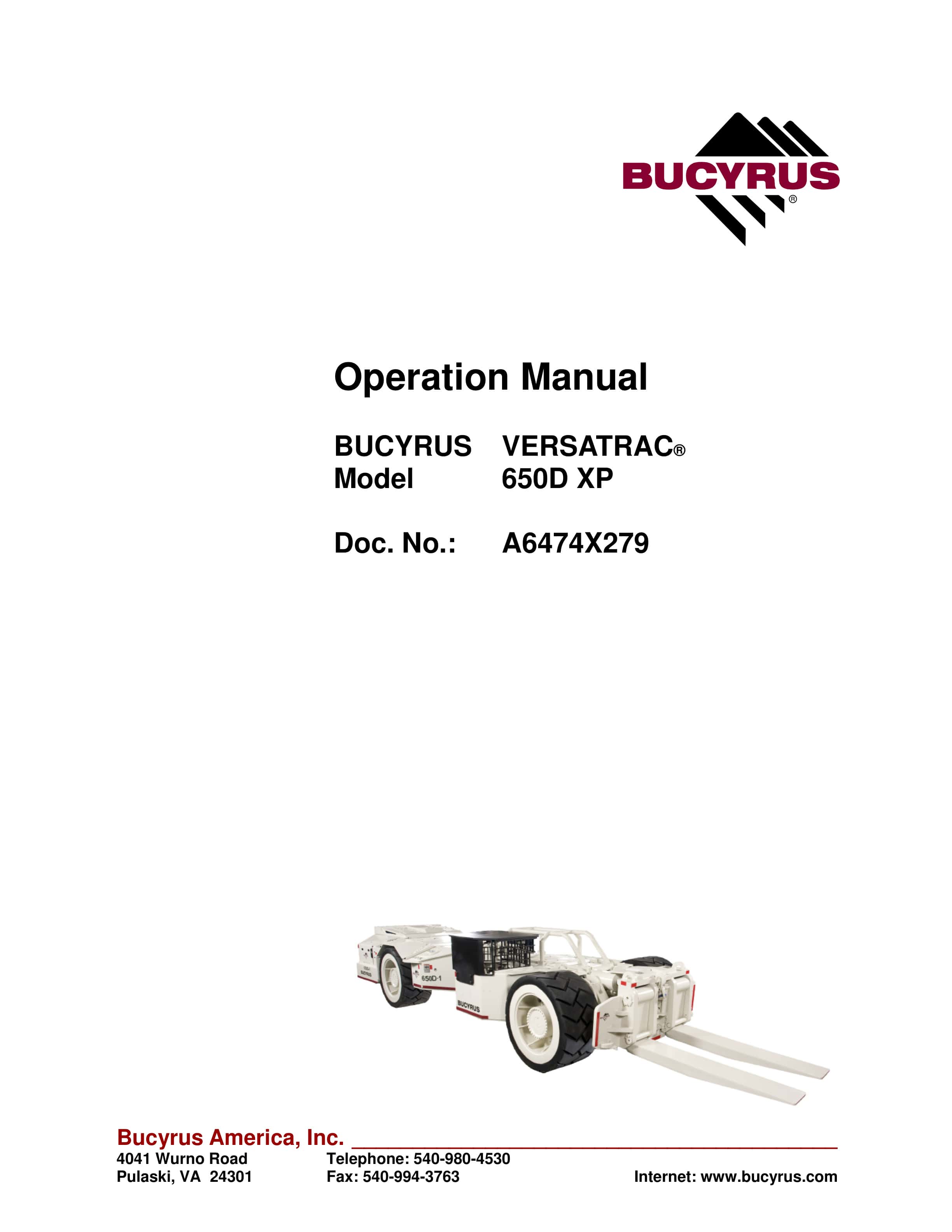
Bucyrus 650D XP Versatrac Operation Manual A6474X279
$30.00
- Type Of Manual: Operation Manual
- Manual ID: A6474X279
- Number of Pages: 340
- Size: 25.8MB
- Format: PDF
Product details
-
Model List:
- 650D XP Versatrac
- 1. 1. About this manual
- 2. About this manual ………………………………………………………… 1.3
- 3. Before starting to work………………………………………………… 1.3
- 4. Who is this operating manual intended for? …………………… 1.3
- 5. What is the purpose of this operating manual? ………………. 1.4
- 6. Characters and symbols ……………………………………………… 1.5
- 7. 2. Your safety
- 8. Your safety …………………………………………………………………… 2.3
- 9. Personnel………………………………………………………………….. 2.4
- 10. Operation ……………………………………………………………… 2.4
- 11. Installation and repair……………………………………………… 2.4
- 12. Operating conditions…………………………………………………… 2.5
- 13. Intended use …………………………………………………………. 2.5
- 14. Unauthorized use…………………………………………………… 2.5
- 15. Safety instructions………………………………………………………. 2.7
- 16. General rules: ……………………………………………………….. 2.7
- 17. Storage and transport …………………………………………….. 2.8
- 18. Pre-start inspection ………………………………………………… 2.8
- 19. Installation and start-up…………………………………………… 2.9
- 20. Operation ……………………………………………………………… 2.9
- 21. Stopping……………………………………………………………….2.10
- 22. Maintenance and repair ………………………………………….2.10
- 23. Diesel emissions ……………………………………………………2.11
- 24. Handling of hydraulic fluids……………………………………..2.13
- 25. Overview of the safety instructions……………………………….2.17
- 26. Chapter 2: Safety instructions………………………………….2.17
- 27. Chapter 3: Storage and transport …………………………….2.17
- 28. Chapter 4: Installation…………………………………………….2.17
- 29. Chapter 5: Operation ……………………………………………..2.18
- 30. Chapter 6: Technical data……………………………………….2.27
- 31. 3. Storage and transport
- 32. Storage and transport …………………………………………………… 3.3
- 33. Storage …………………………………………………………………….. 3.3
- 34. Storage of the machine and spare parts……………………. 3.3
- 35. Transport…………………………………………………………………… 3.4
- 36. Before transport …………………………………………………….. 3.5
- 37. 4. Installation
- 38. Installation……………………………………………………………………. 4.3
- 39. Points to observe prior to installation…………………………….. 4.3
- 40. Who is allowed to carry out installation?……………………. 4.3
- 41. Which tools are required for installation?…………………… 4.3
- 42. Notes on installation……………………………………………….. 4.4
- 43. Pre-installation check list ………………………………………… 4.5
- 44. Safety features………………………………………………………. 4.6
- 45. 5. Operation
- 46. Pre-operation suggestions ……………………………………………. 5.3
- 47. Operation ……………………………………………………………………… 5.4
- 48. How to operate the VERSATRAC®……………………………….. 5.4
- 49. Who is allowed to operate the VERSATRAC®……………. 5.4
- 50. When can operation be started?………………………………. 5.4
- 51. Controls and indicators ……………………………………………….. 5.5
- 52. Operator’s compartment – left and center ………………….. 5.5
- 53. Operator’s compartment – right ………………………………… 5.6
- 54. Hazard zone………………………………………………………………. 5.16
- 55. Starting procedure………………………………………………………. 5.17
- 56. Shutdown procedure…………………………………………………… 5.18
- 57. Towing a disabled machine …………………………………………. 5.19
- 58. Instructions on the maintenance …………………………………… 5.21
- 59. Important notes ……………………………………………………… 5.21
- 60. Before maintenance ……………………………………………….. 5.21
- 61. Critical torque values………………………………………………. 5.23
- 62. Lubricants, fluids and capacities ………………………………. 5.23
- 63. Specific lubrication and maintenance schedule………….. 5.24
- 64. Specific lubrication and maintenance procedure …………….. 5.28
- 65. Pre-shift………………………………………………………………… 5.28
- 66. Every third shift ……………………………………………………… 5.31
- 67. Weekly………………………………………………………………….. 5.38
- 68. First 50 hours of service………………………………………….. 5.58
- 69. Every three months ………………………………………………… 5.59
- 70. Every 100 hours …………………………………………………….. 5.64
- 71. Every 500 hours …………………………………………………….. 5.66
- 72. Every six months……………………………………………………. 5.68
- 73. Every twelve months ………………………………………………. 5.70
- 74. Servicing heavy duty air filter elements …………………………. 5.71
- 75. Diesel emissions maintenance …………………………………………. 5.75
- 76. Introduction (emissions)………………………………………………. 5.75
- 77. Diesel emissions ………………………………………………………… 5.75
- 78. Diesel emissions stall test……………………………………………. 5.77
- 79. Operational issues ……………………………………………………… 5.79
- 80. Best practices…………………………………………………………….. 5.80
- 81. Proactive attitudes………………………………………………………. 5.83
- 82. Typical exhaust gas components………………………………….. 5.85
- 83. Carbon dioxide ………………………………………………………. 5.85
- 84. Carbon monoxide…………………………………………………… 5.85
- 85. Oxides of nitrogen ………………………………………………….. 5.85
- 86. Hydrocarbons………………………………………………………… 5.85
- 87. Particulate matter …………………………………………………… 5.86
- 88. Oxides of sulfur ……………………………………………………… 5.86
- 89. Smoke ………………………………………………………………….. 5.86
- 90. Engine systems and conditions
- 91. that affect diesel emissions………………………………………….. 5.87
- 92. Combustion chamber design …………………………………… 5.87
- 93. Intake manifold system …………………………………………… 5.89
- 94. Operating conditions that affect emissions ………………… 5.90
- 95. Low turbocharger boost pressure …………………………….. 5.91
- 96. High exhaust backpressure……………………………………… 5.91
- 97. High crankcase pressure ………………………………………… 5.93
- 98. Overview of six engine systems………………………………………. 5.94
- 99. Overview of engine introduction …………………………………… 5.94
- 100. Intake system ……………………………………………………………. 5.95
- 101. Dry type air cleaners………………………………………………. 5.96
- 102. Air induction piping…………………………………………………. 5.97
- 103. Aftercoolers…………………………………………………………… 5.97
- 104. Air-to-air aftercoolers ……………………………………………… 5.98
- 105. Water aftercoolers………………………………………………….. 5.98
- 106. Intake system recommendations ……………………………… 5.99
- 107. Servicing the intake system …………………………………….. 5.100
- 108. Job aid checklist (Intake System) …………………………….. 5.101
- 109. Exhaust system …………………………………………………………. 5.102
- 110. Exhaust system recommendations…………………………… 5.103
- 111. Exhaust after treatment system maintenance ……………. 5.104
- 112. Job aid checklist for exhaust system ………………………… 5.106
- 113. Introduction to tools used for exhaust system analysis .. 5.107
- 114. ECOM AC+ gas analyzer……………………………………. 5.107
- 115. UGAS software application …………………………………. 5.109
- 116. Testing protocol…………………………………………………. 5.109
- 117. Pre-test conditions …………………………………………….. 5.110
- 118. Emissions testing protocol ………………………………….. 5.110
- 119. Basic emission equipment operation ………………………… 5.111
- 120. Undiluted diesel particulate measurement…………….. 5.111
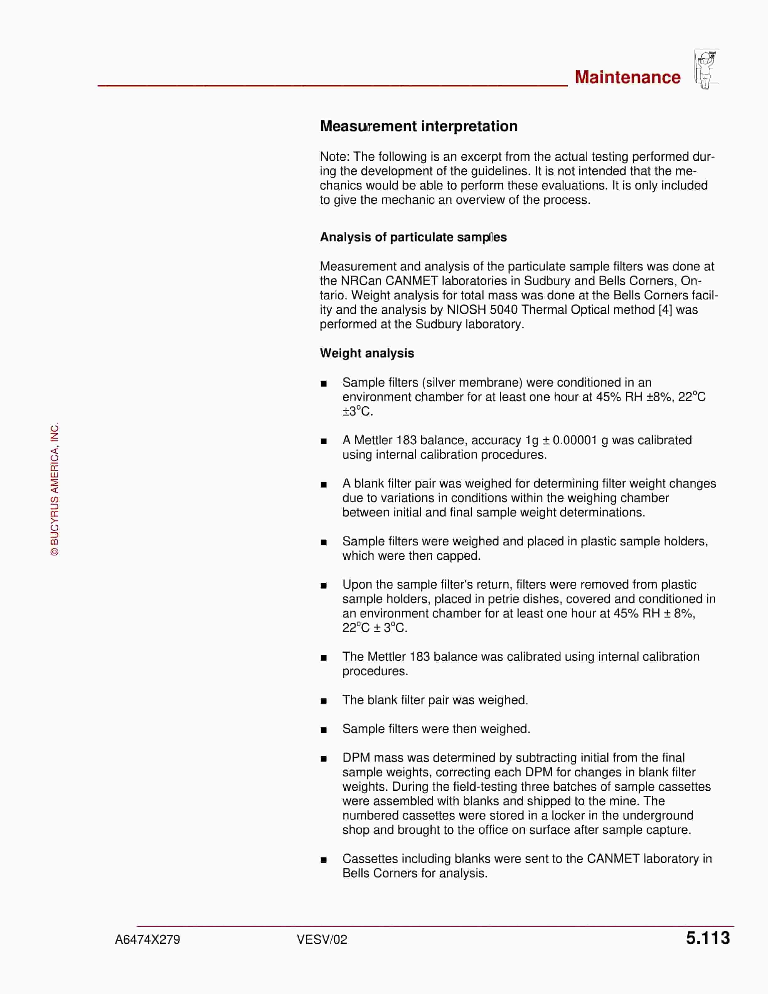
- 121. Measurement interpretation ………………………………… 5.113
- 122. Analysis of particulate samples……………………………. 5.113
- 123. Thermal optical method ……………………………………… 5.114
- 124. Job aid checklist for exhaust system analysis tools… 5.114
- 125. ECOM AC+ gas analyzer……………………………………. 5.115
- 126. Particulate sampling – Gilian pump ………………………. 5.115
- 127. Intake testing…………………………………………………….. 5.116
- 128. Intake restrictions and exhaust backpressure ……….. 5.117
- 129. Fuel injection system ………………………………………………….. 5.118
- 130. Introduction (Fuel injection system) ………………………….. 5.118
- 131. Injection pump or injector failure………………………………. 5.119
- 132. Inadequate fuel supply……………………………………………. 5.119
- 133. Incorrect injection pump or injector timing …………………. 5.120
- 134. Advanced timing ……………………………………………………. 5.120
- 135. Retarded timing……………………………………………………… 5.120
- 136. Fuel system types ………………………………………………….. 5.120
- 137. Individual unit jerk pumps ……………………………………….. 5.122
- 138. Inline pump system ………………………………………………… 5.123
- 139. Distributor pump system …………………………………………. 5.124
- 140. Cummins PT fuel system………………………………………… 5.124
- 141. Unit injectors …………………………………………………………. 5.125
- 142. Electronically controlled fuel injection systems…………… 5.125
- 143. Fuel injection system recommendations……………………. 5.126
- 144. Job aid checklist for fuel systems …………………………….. 5.127
- 145. Cooling systems…………………………………………………………. 5.128
- 146. Cooling system recommendations……………………………. 5.128
- 147. Cooling system maintenance…………………………………… 5.129
- 148. Coolant mixture……………………………………………………… 5.129
- 149. Conditioner and inhibitors ……………………………………….. 5.129
- 150. Cleaning and flushing …………………………………………….. 5.130
- 151. Troubleshooting …………………………………………………….. 5.130
- 152. Thermostats ………………………………………………………….. 5.130
- 153. Aeration in coolant …………………………………………………. 5.130
- 154. Radiator cap relief valve …………………………………………. 5.131
- 155. Temperature probe ………………………………………………… 5.131
- 156. Job aid checklist for cooling system) ………………………… 5.132
- 157. Diesel fuel and fuel supply systems ……………………………… 5.133
- 158. Introduction (Diesel fuel and fuel supply systems) ……… 5.133
- 159. Best practice recommendations……………………………….. 5.133
- 160. Sulfur content………………………………………………………… 5.134
- 161. Cetane number ……………………………………………………… 5.134
- 162. Viscosity……………………………………………………………….. 5.134
- 163. Flashpoint……………………………………………………………… 5.134
- 164. Fuel quality and handling recommendations ……………… 5.135
- 165. Lubrication ………………………………………………………………… 5.136
- 166. Lubrication recommendations………………………………….. 5.136
- 167. Lubrication classification …………………………………………. 5.137
- 168. Combined service applications ………………………………… 5.138
- 169. Lubrication system checks………………………………………. 5.138
- 170. Conclusion…………………………………………………………….. 5.139
- 171. Diesel emissions – job aid check list …………………………….. 5.140
- 172. Hydraulic system………………………………………………………… 5.141
- 173. Adjustment procedures……………………………………………….. 5.143
- 174. Pressure compensated (PC) control…………………………. 5.143
- 175. Main relief valve …………………………………………………….. 5.144
- 176. Steering section port relief valves…………………………….. 5.145
- 177. Pressure limiter ……………………………………………………… 5.145
- 178. Pressure reducing valve …………………………………………. 5.146
- 179. Bell crank bi-directional valve ………………………………….. 5.146
- 180. Auxiliary relief valve ……………………………………………….. 5.148
- 181. Dif-lok valve…………………………………………………………… 5.149
- 182. Hand pump relief valve …………………………………………… 5.150
- 183. Replacement of wear parts………………………………………….. 5.151
- 184. Tire/wheel installation …………………………………………….. 5.151
- 185. Axle removal/installation …………………………………………. 5.155
- 186. Drive shaft removal/installation………………………………… 5.158
- 187. Accumulator operation/precharging………………………….. 5.159
- 188. Ejector blade and cylinder removal/installation…………… 5.161
- 189. Canopy/cab removal ………………………………………………. 5.163
- 190. Steering cylinder ……………………………………………………. 5.164
- 191. Tilt cylinder……………………………………………………………. 5.166
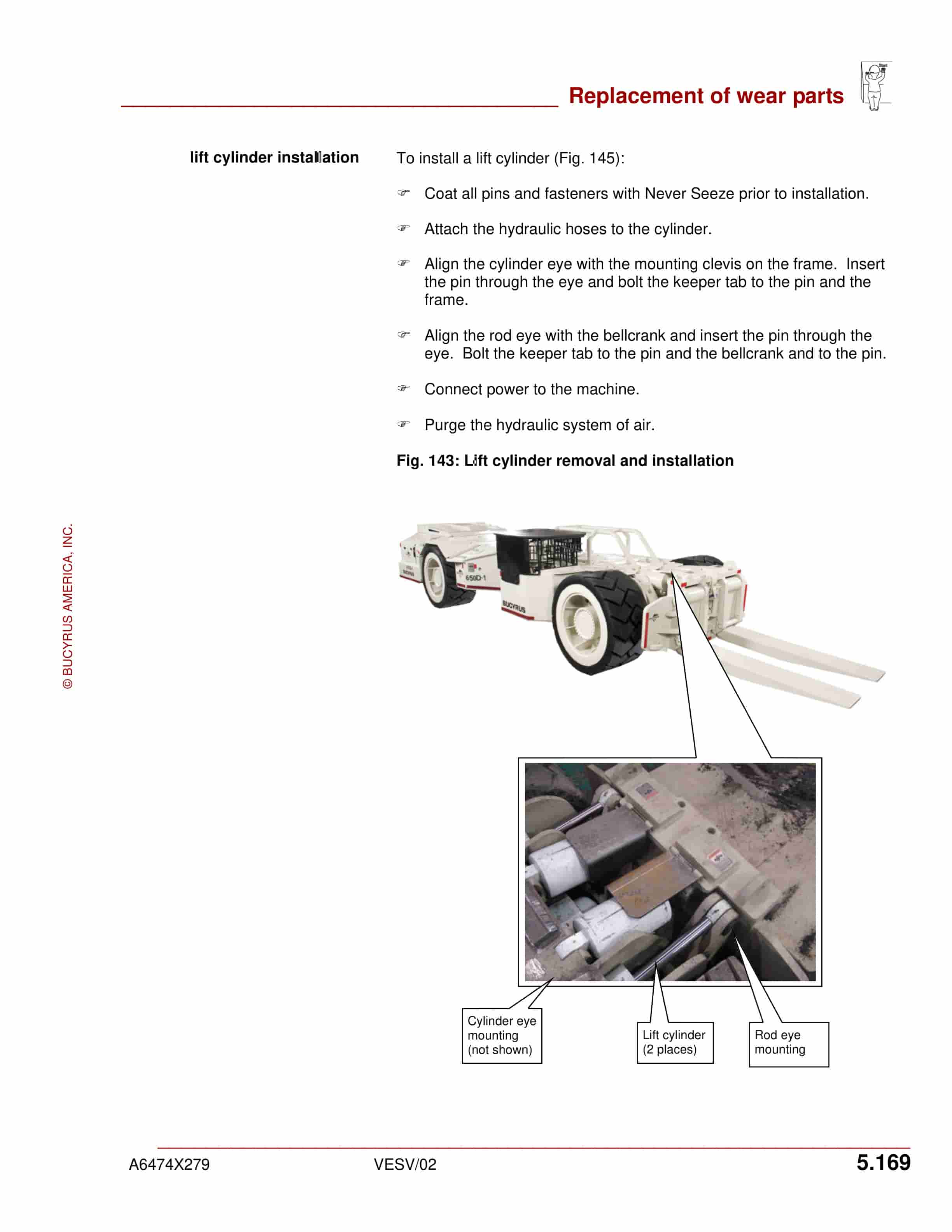
- 192. Lift cylinder……………………………………………………………. 5.168
- 193. Brake bleeding procedure……………………………………….. 5.170
- 194. DST Dry System™……………………………………………………… 5.171
- 195. On-board Cleaning System™ ………………………………….. 5.171
- 196. Background ………………………………………………………. 5.171
- 197. Activating………………………………………………………….. 5.171
- 198. Diagnosing high exhaust backpressure………………… 5.173
- 199. Procedure to replace the particulate filter ……………… 5.175
- 200. Replacement exhaust particulate filters………………… 5.176
- 201. Pre-operating inspection…………………………………………. 5.177
- 202. MSHA requirements…………………………………………… 5.177
- 203. System requirements …………………………………………. 5.177
- 204. Pre-operating inspection checklist ……………………….. 5.178
- 205. Operating instructions…………………………………………………. 5.179
- 206. Background …………………………………………………………. 5.179
- 207. Starting the engine ……………………………………………….. 5.179
- 208. Starting a cold engine (after extended parking) ………… 5.180
- 209. Automatic safety shutdown features ……………………….. 5.181
- 210. Manual shutdown features …………………………………….. 5.182
- 211. Excessive idling……………………………………………………. 5.182
- 212. Operating recommendations………………………………….. 5.182
- 213. Stopping the engine and parking the machine………….. 5.183
- 214. Carbon Monoxide (CO) sampling procedure………………….. 5.184
- 215. Background …………………………………………………………. 5.184
- 216. Reasons for monitoring engine-out CO emissions ……. 5.185
- 217. Reasons for monitoring treated CO emissions (opt)….. 5.185
- 218. Permanently installed CO sampling ports ………………… 5.186
- 219. CO sampling procedure ………………………………………… 5.187
- 220. CO sampling instruments………………………………………. 5.188
- 221. Maintenance for flameproof ports …………………………… 5.189
- 222. CO sampling recordkeeping (sample form) ……………… 5.190
- 223. Cooling system filling procedure…………………………………… 5.191
- 224. Safety shutdown system……………………………………………… 5.192
- 225. System description (pneumatic system) ………………….. 5.192
- 226. Starting the system……………………………………………….. 5.193
- 227. Manual system shutdown………………………………………. 5.193
- 228. Manual emergency shutdown ………………………………… 5.193
- 229. Automatic temperature shutdown feature ………………… 5.193
- 230. Automatic low oil pressure shutdown feature……………. 5.194
- 231. MSHA documentation ………………………………………………………. 5.195
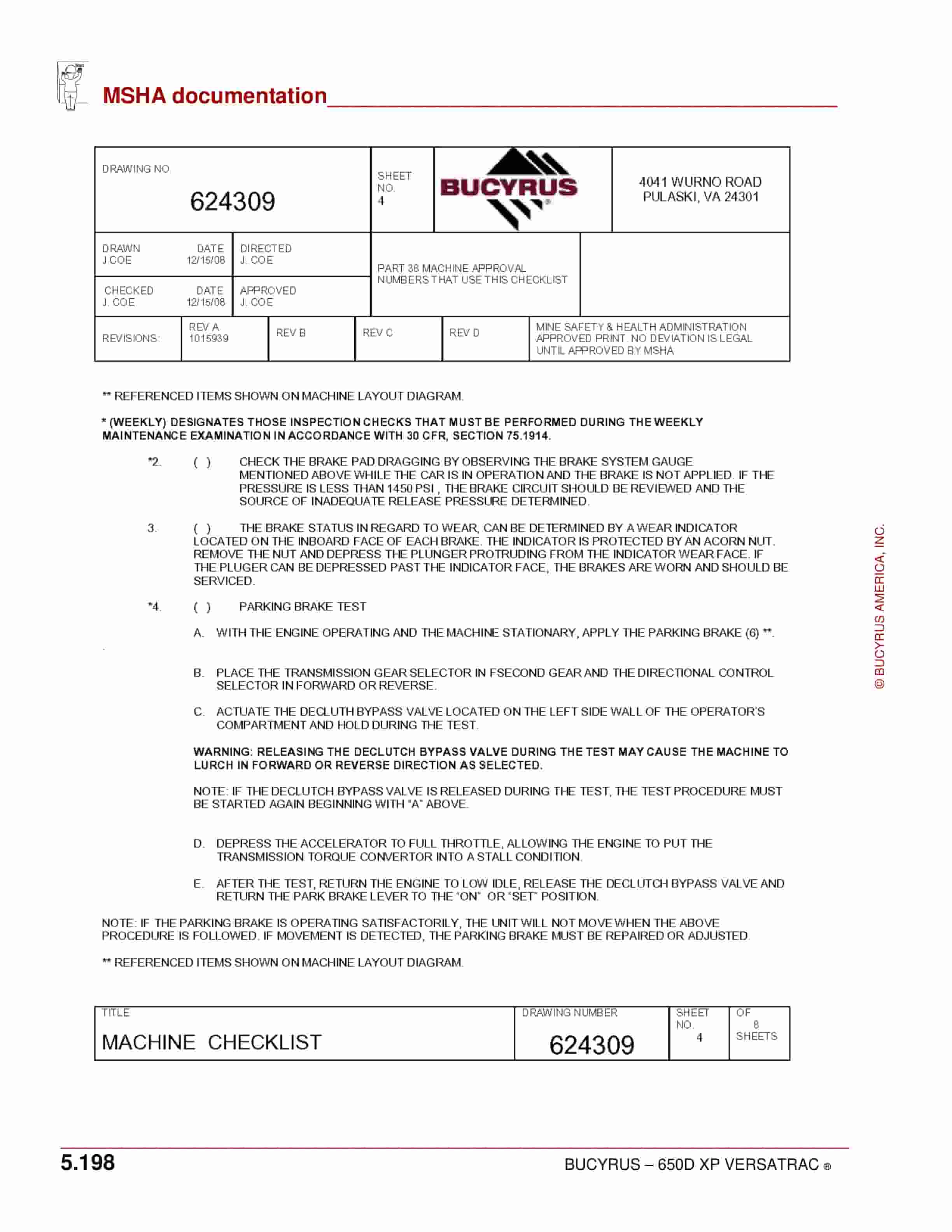
- 232. Machine permissibility (drawing 624309) ………………………. 5.195
- 233. Power package permissibility (drawing M255-001-01)…….. 5.203
- 234. Electric package permissibility (drawing M261-008-01) …… 5.215
- 235. General arrangement (drawing 624312) ……………………….. 5.220
- 236. Electrical schematic (drawing M261-003-01) …………………. 5.222
- 237. Electrical installation (drawing M261-010-01)…………………. 5.223
- 238. Alternator installation (drawing M250-107-01)………………… 5.224
- 239. Starting circuit – Cummins 8.3 (drawing M250-012-01)……. 5.225
- 240. Cooling system (drawing M250-008-01)………………………… 5.226
- 241. Water injection system, pneumatic (drawing M265-006-01) 5.227
- 242. CO monitoring ports (drawing M250-006-01) …………………. 5.228
- 243. Shutdown system (drawing M250-007-01)…………………….. 5.229
- 244. Fuel system, C8.3 (drawing 624310)…………………………….. 5.230
- 245. Operator’s compartment (drawing 624311)……………………. 5.231
- 246. Troubleshooting procedures………………………………………………. 5.233
- 247. Hydraulic system (general) ………………………………………….. 5.234
- 248. Brakes………………………………………………………………………. 5.237
- 249. Hydraulic cylinders……………………………………………………… 5.239
- 250. Hydraulic pump………………………………………………………….. 5.240
- 251. Valves ………………………………………………………………………. 5.242
- 252. Engine………………………………………………………………………. 5.243
- 253. Converter ………………………………………………………………….. 5.254
- 254. Transmission……………………………………………………………… 5.256
- 255. Fuel injector ………………………………………………………………. 5.257
- 256. Compressor ………………………………………………………………. 5.257
- 257. Leaking intake system ………………………………………………… 5.259
- 258. Air intake system restriction and fuel flow ……………………… 5.259
- 259. Catalyst failure …………………………………………………………… 5.259
- 260. Exhaust particulate filter failure…………………………………….. 5.259
- 261. 6. Technical data
- 262. Technical data………………………………………………………………. 6.3
- 263. Components of the 650D Permissible VERSATRAC®…….. 6.3
- 264. Technical data……………………………………………………………. 6.3
- 265. Tightening torques ……………………………………………………… 6.4
- 266. Permissible data ……………………………………………………….. 6.11
- 267. Lubrication fluids and greases ………………………………… 6.11
- 268. 7. For your information
- 269. For your information …………………………………………………….. 7.3
- 270. Our service………………………………………………………………… 7.3
- 271. Service address …………………………………………………….. 7.3
- 272. Rebuild facility address …………………………………………… 7.4
Related products
-
Bucyrus 1370W Walking Dragline Technical Manual BI005572
$30.00 Add to cart -
Bucyrus 1260W Walking Dragline Technical Manual BI005568
$30.00 Add to cart -
Bucyrus 1370W Walking Dragline Technical Manual BI005574
$30.00 Add to cart -
Bucyrus 1370W Walking Dragline Technical Manual BI005556
$30.00 Add to cart -
Bucyrus 1370W Walking Dragline Technical Manual BI005573
$30.00 Add to cart


