

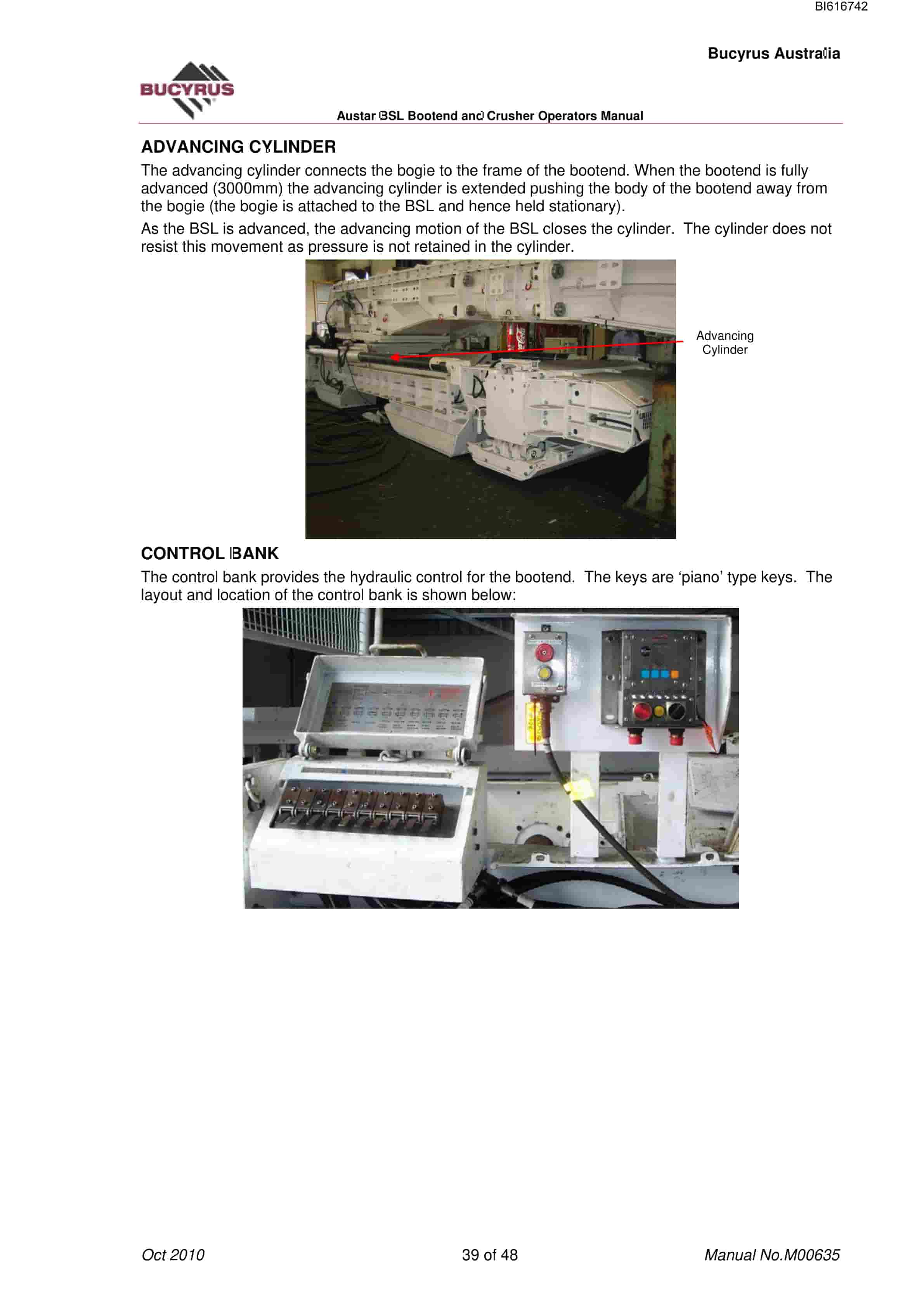
Bucyrus Austar BSL Bootend And Crusher Technical Manual BI616742
$30.00
- Type Of Manual: Technical Manual
- Manual ID: BI616742
- Number of Pages: 49
- Size: 1.9MB
- Format: PDF
Product details
-
Model List:
- Austar BSL Bootend And Crusher
- 1. M00635.pdf
- 1.1. General Safety
- 1.1.1. Residual Risk
- 1.1.2. Supplementary Regulations
- 1.1.3. PERSONNEL
- 1.1.3.1. Operation and maintenance
- 1.1.3.2. Qualification
- 1.1.4. USE IN CONFORMANCE WITH SPECIFICATIONS
- 1.1.5. USE CONTRARY TO SPECIFICATIONS
- 1.1.6. SAFETY INSTRUCTIONS
- 1.1.6.1. Basic principles
- 1.1.6.2. Lighting
- 1.1.6.3. Signalling Systems and Protective Devices
- 1.1.6.4. Emergency Stop
- 1.1.6.5. Support Lock-out Switch
- 1.1.6.6. Moving Parts
- 1.1.7. STORAGE AND TRANSPORT
- 1.1.8. HYDRAULICS
- 1.1.8.1. Handling of Hydraulic Fluids
- 1.1.8.2. Maintenance and Repair
- 1.1.8.3. Permissible Hoses
- 1.1.8.4. Installation of Hydraulic Hoses
- 1.2. Storage and transport
- 1.2.1. STORAGE
- 1.2.1.1. Storing the equipment
- 1.2.2. TRANSPORT
- 1.2.2.1. Before transport
- 1.2.2.2. Transport of the components
- 1.3. Assembly
- 1.3.1. PRIOR TO ASSEMBLY
- 1.3.1.1. Who is allowed to carry out assembly work
- 1.3.1.2. Assembly notes
- 1.3.2. ASSEMBLY CRUSHER
- 1.3.2.1. Installing the individual crusher components into the stageloader
- 1.3.2.2. Installing the assembled crusher into the stageloader
- 1.3.3. DISMANTLING
- 1.4. Introduction
- 1.4.1. FUNCTIONS AND PURPOSE OF BSL
- 1.4.2. MAJOR COMPONENTS OF BSL
- 1.4.2.1. BSL Return Head
- 1.4.2.2. Minipans
- 1.4.2.3. BSL Gooseneck
- 1.4.2.4. Crusher
- 1.4.2.5. BSL with Roadway Shield
- 1.4.3. WATER CIRCUIT
- 1.4.4. GREASING
- 1.5. Carry Out Start, Stop and Shut-down Procedures – BSL
- 1.5.1. NORMAL START
- 1.5.2. TEMPORARY STOP PROCEDURE
- 1.5.3. NORMAL SHUTDOWN PROCEDURE
- 1.5.4. BSL START-UP SEQUENCE
- 1.5.5. RUNNING BSL WITH SLOWRUNNERS
- 1.6. Fluid Coupling Gearbox Maintenance
- 1.6.1. CHECKING AND FILLING BSL / CRUSHER FLUID COUPLING
- 1.6.2. CHECKING AND CHANGING BSL GEARBOX OIL
- 1.6.2.1. To check the BSL drive oil level
- 1.6.2.2. To top up oil
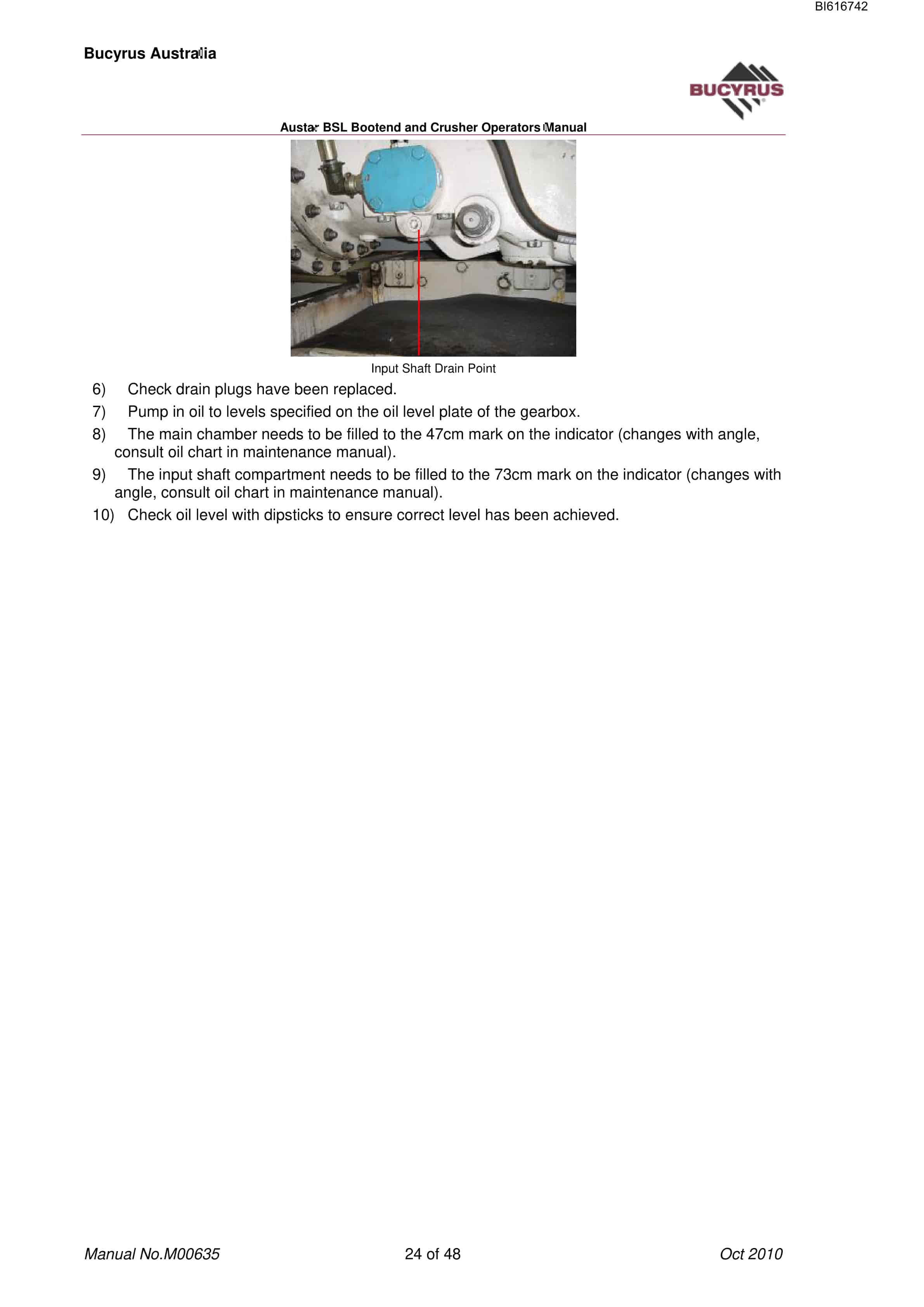
- 1.6.2.3. To drain oil
- 1.7. Crusher
- 1.7.1. TECHNICAL DATA
- 1.7.2. TECHNICAL DATA SHEET
- 1.7.3. MAIN COMPONENTS
- 1.7.4. TECHNICAL DESCRIPTION
- 1.7.4.1. Crusher housing and substructure with crusher pan
- 1.7.4.2. Impact roll
- 1.7.4.3. Turn able Impact Head
- 1.7.4.4. Roll height adjustment
- 1.7.4.5. Central lubrication
- 1.7.5. TIGHTENING TORQUES
- 1.7.5.1. Screws and nuts with metric coarse thread DIN 13
- 1.7.6. OPERATION
- 1.7.6.1. Commissioning of the crusher plant
- 1.7.6.2. Before commissioning
- 1.7.6.3. Notes for electrics
- 1.7.7. TEST RUN AND START UP
- 1.7.8. OPERATION OF THE CRUSHER PLANT
- 1.7.8.1. General
- 1.7.8.2. Roll height adjustment
- 1.8. Bootend
- 1.8.1. ISOLATING BOOTEND
- 1.8.2. FUNCTIONS AND PURPOSE OF BOOTEND
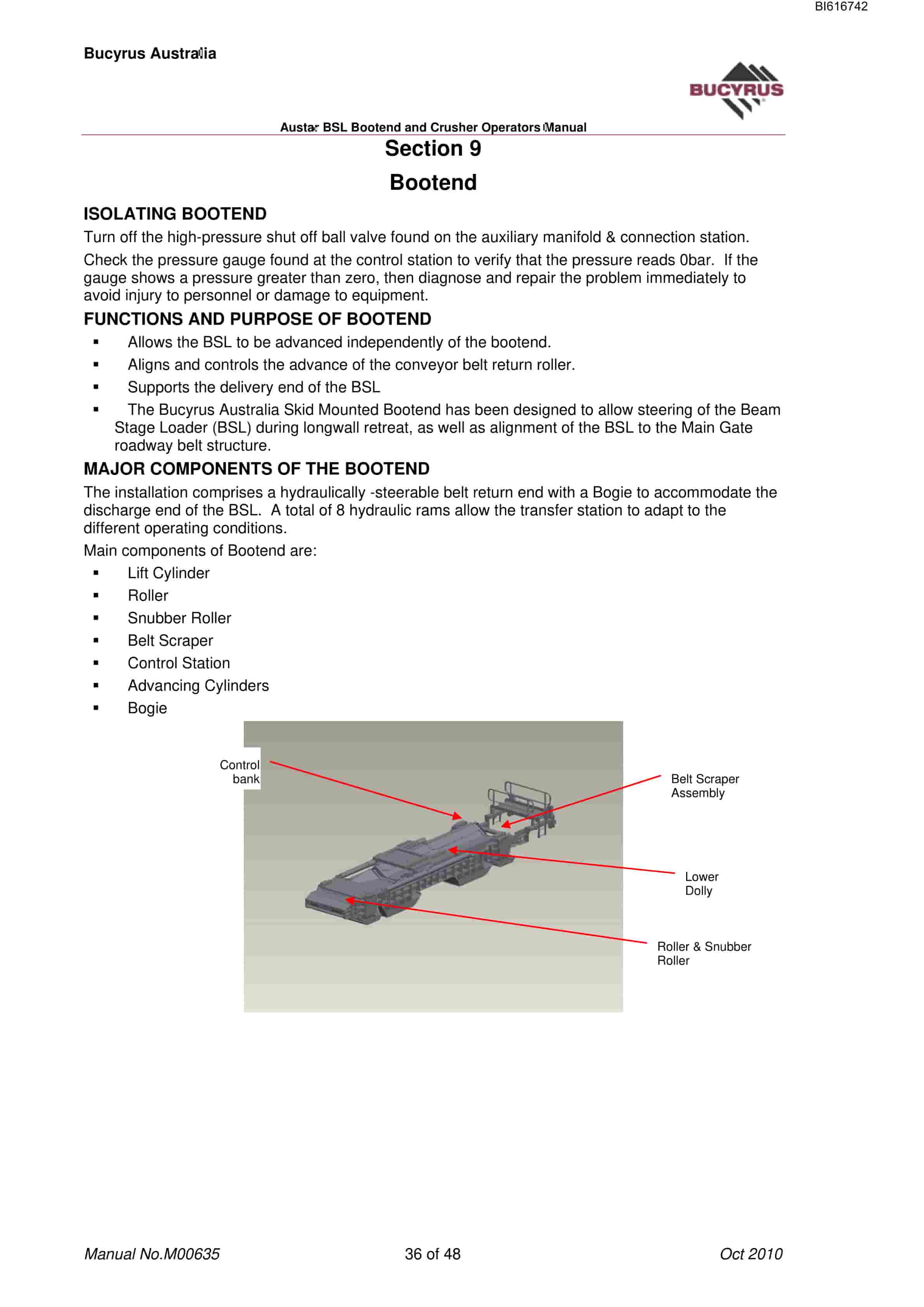
- 1.8.3. MAJOR COMPONENTS OF THE BOOTEND
- 1.8.4. ROLLER SNUBBER ROLLER
- 1.8.5. BELT SCRAPER
- 1.8.6. LIFT CYLINDERS
- 1.8.7. SIDE SHIFT CYLINDER
- 1.8.8. ADVANCING CYLINDER
- 1.8.9. CONTROL BANK
- 1.9. Carry Out Start, Stop and Shut-down Procedures – Bootend
- 1.9.1. CONTROL BANK
- 1.9.2. BOOTEND SEQUENCE OF OPERATION
- 1.9.3. PERFORM A SIDE SHIFT OPERATION
- 1.9.4. BOOTEND LINE AND LEVEL
- 1.9.5. BELT SIGNAL LINE CABLE REALER
- 1.10. Lubrication Inspections
- 1.10.1. BOOTEND
- 1.10.1.1. Greasing
- 1.10.1.2. Water Circuit
- 1.10.1.3. Inspection (Shift)
- 1.10.1.4. Inspection (Daily)
- 1.10.2. CRUSHER
- 1.10.2.1. Lubrication
- 1.10.2.2. Changing or turning the impact heads
Related products
-
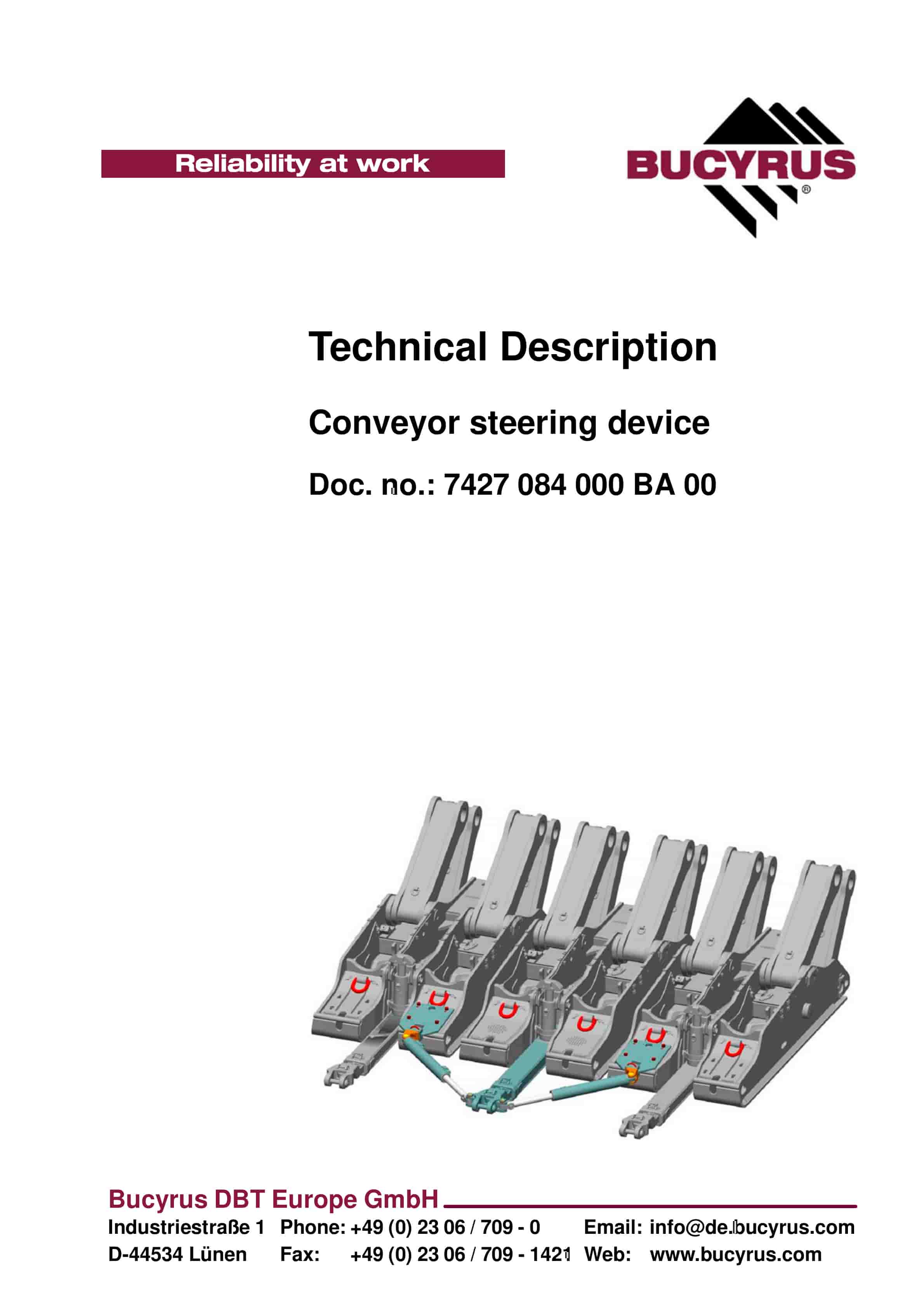
Bucyrus Conveyor Steering Device Technical Description 7427 084 000 BA 00
$30.00 Add to cart -
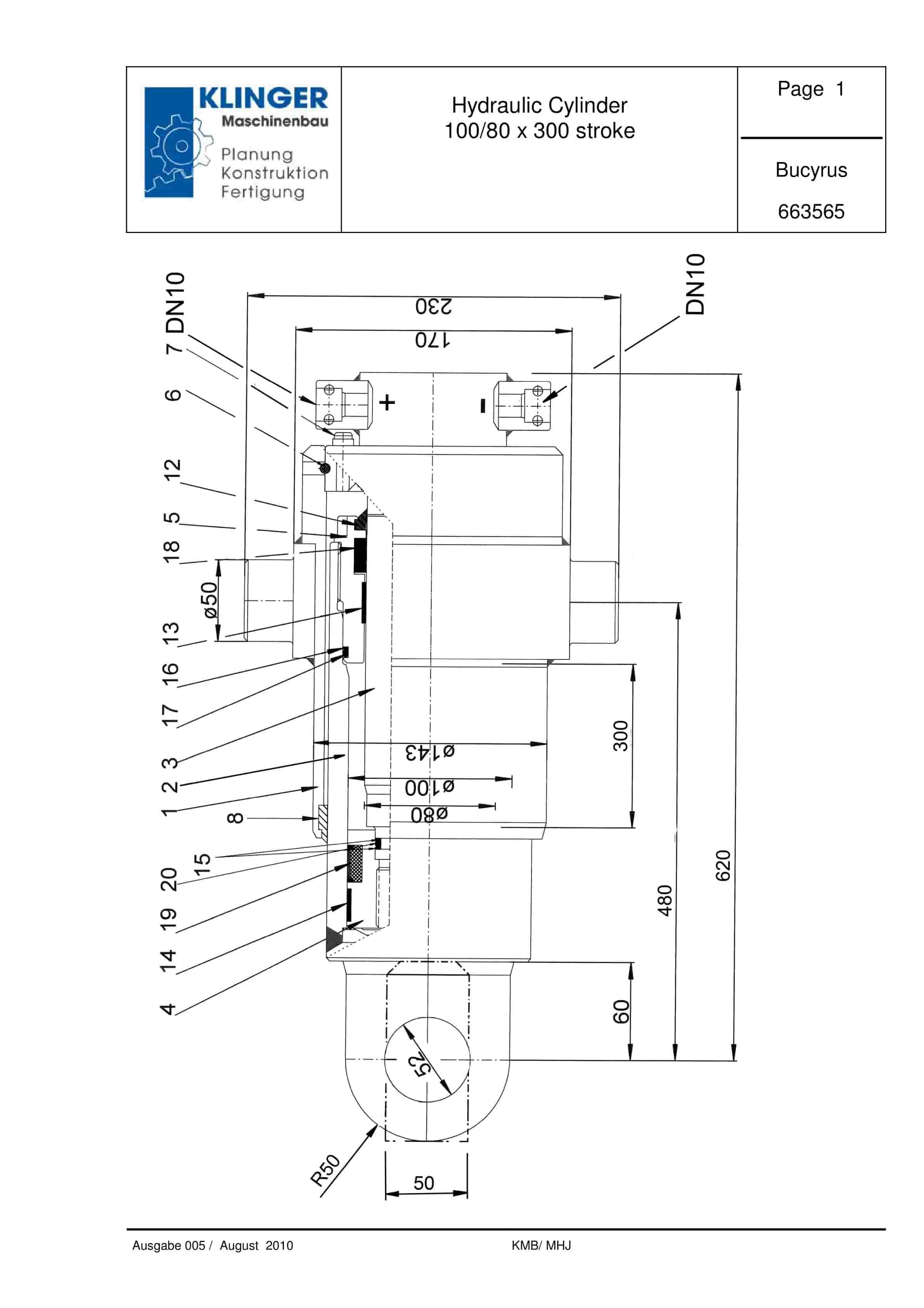
Bucyrus Hydraulic Cylinder 100-80 x 300 Stroke Service Parts List 663565
$30.00 Add to cart -
Bucyrus Continuous Miner Spare Parts List 907783
$30.00 Add to cart -
Bucyrus Continuous Miner Spare Parts List 907781
$30.00 Add to cart -
Bucyrus Belt System Spare Parts List 308651
$30.00 Add to cart


