

Bucyrus Austar Shield Technical Manual BI616746
$30.00
- Type Of Manual: Technical Manual
- Manual ID: BI616746
- Number of Pages: 112
- Size: 3.4MB
- Format: PDF
Product details
-
Model List:
- Austar Shield
- 1. M00639.pdf
- 1.1. General Safety
- 1.1.1. Residual Risk
- 1.1.1.1. Supplementary Regulations
- 1.1.2. Personnel
- 1.1.3. Operation and maintenance
- 1.1.3.1. Qualification
- 1.1.4. Use in conformance with specifications
- 1.1.5. Use contrary to specifications
- 1.1.6. Safety instructions
- 1.1.6.1. Basic principles
- 1.1.6.2. Prerequisite
- 1.1.6.3. Lighting
- 1.1.6.4. Signalling Systems and Protective Devices
- 1.1.6.5. Emergency Stop
- 1.1.6.6. Support Lock-out Switch
- 1.1.6.7. Moving Parts
- 1.1.6.8. Automatic Mode
- 1.1.7. Storage and transport
- 1.1.8. Installation
- 1.1.9. Operation
- 1.1.10. Maintenance
- 1.1.10.1. Hydraulics
- 1.1.10.2. Handling of Hydraulic Fluids
- 1.1.10.3. Maintenance and Repair
- 1.1.10.4. Permissible Hoses
- 1.1.10.5. Installation of Hydraulic Hoses
- 1.2. Storage and transport
- 1.2.1. Storage
- 1.2.1.1. Storage of new equipment
- 1.2.1.2. Exposure to Sunlight
- 1.2.1.3. Natural Ageing
- 1.2.1.4. Moisture and Dirt
- 1.2.1.5. Short Term Storage
- 1.2.1.6. Long Term Storage
- 1.2.1.7. Plastic Deformation
- 1.2.1.8. Random Sample Inspection
- 1.2.1.9. HFA Fluids
- 1.2.2. Used equipment
- 1.2.2.1. Corrosion Protection
- 1.2.3. Transport
- 1.2.3.1. Transport Units
- 1.2.3.2. Points of Attachment
- 1.2.4. Lifting Points
- 1.2.4.1. Temperatures Below Freezing
- 1.2.4.2. Electrical and Electronic Components
- 1.2.4.3. Transport Safety Devices and Transport Units
- 1.3. Introduction
- 1.3.1. General Data Information
- 1.3.2. One Web Back System (OWB)
- 1.3.3. Face and Gate End Shields
- 1.3.4. Top Coal Caving
- 1.3.5. Safe Working Areas
- 1.3.6. Front Walkway
- 1.3.7. Automatic Operation
- 1.3.8. Canopy Inclination Limitations
- 1.3.9. Relay Bar Assembly Jamming
- 1.4. Face and Gate Shield Components
- 1.4.1. Base, Canopy Caving Shield
- 1.4.2. Lemniscate Linkage
- 1.4.3. Relay Bar
- 1.5. Face and Gate Shield Cylinders
- 1.5.1. Leg Cylinders (Face and Gate)
- 1.5.1.1. Canopy Tilt Cylinder (Face Shield Only)
- 1.5.1.2. DA Ram Front and Rear
- 1.5.1.3. Rear AFC Advancing Cylinder (Face Shields)
- 1.5.1.4. Base Lifting Cylinder
- 1.5.1.5. Flipper Cylinder
- 1.5.1.6. Side Shield Cylinder
- 1.5.1.7. Rear Caving Shield Cylinder
- 1.5.1.8. Rear Caving Door Cylinder
- 1.5.2. Roadway Shield Cylinders
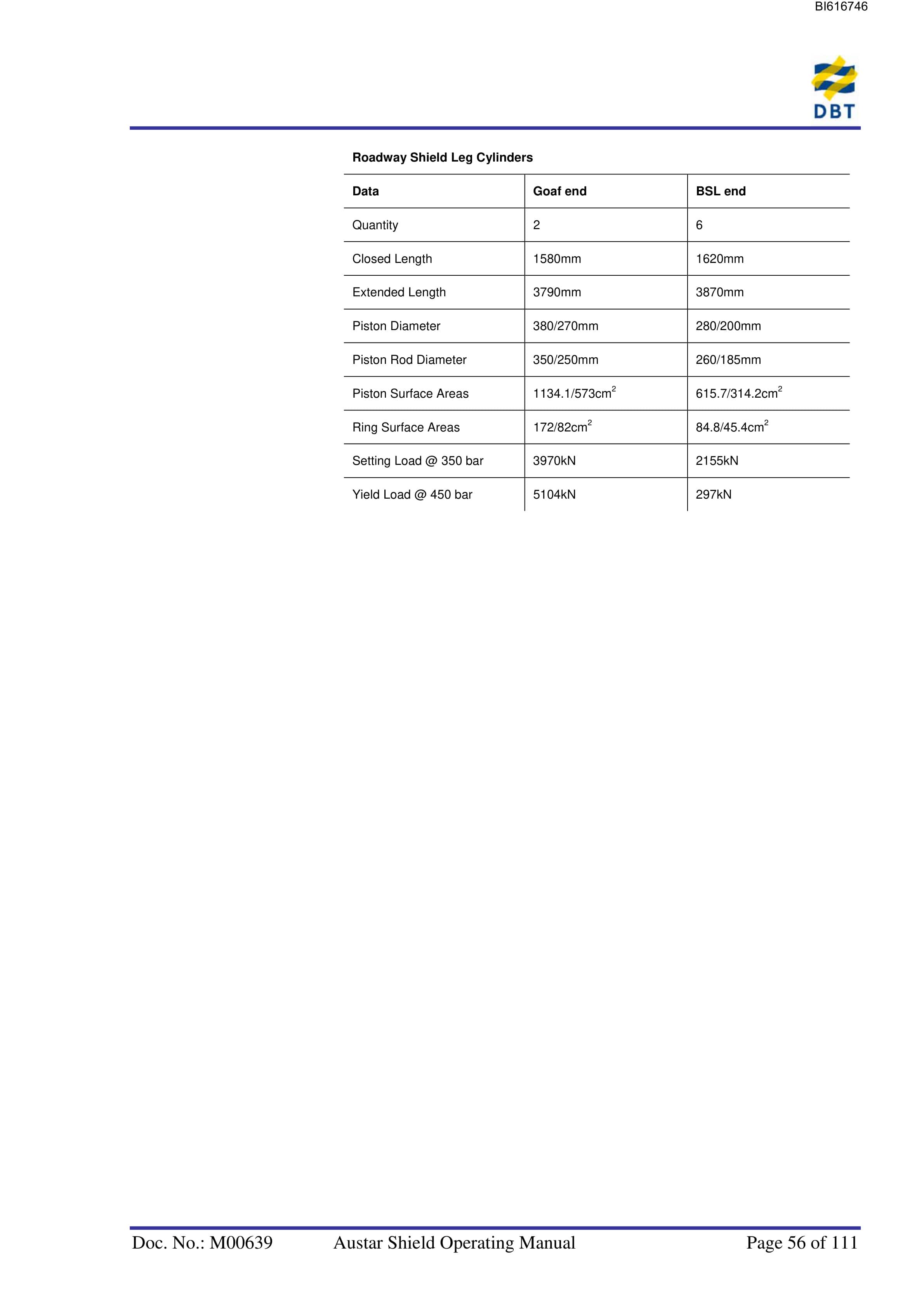
- 1.5.2.1. Roadway Leg Cylinders
- 1.5.2.2. Anti-Topple Cylinders
- 1.5.2.3. Advancing Cylinder
- 1.5.2.4. Side Shift Cylinders
- 1.5.2.5. Vertical Goaf Shield Cylinders
- 1.5.2.6. Side Seal Flipper Shield Cylinders
- 1.5.2.7. Roadway Rear Caving Slide Seal Cylinders
- 1.5.3. Water Sprays
- 1.5.4. Lighting and Indicator Lights
- 1.6. Shield Hydraulics
- 1.6.1. Supply Manifold
- 1.6.2. Main Isolation Valve (350 bar)
- 1.6.3. High Pressure Isolation Valve (420 bar)
- 1.6.4. Water Isolation Valve
- 1.6.5. Leg Cylinder POCV (Pilot Operated Control Valve) Block
- 1.6.5.1. Yield valve
- 1.6.5.2. KN Valve
- 1.6.5.3. Bleed Valve
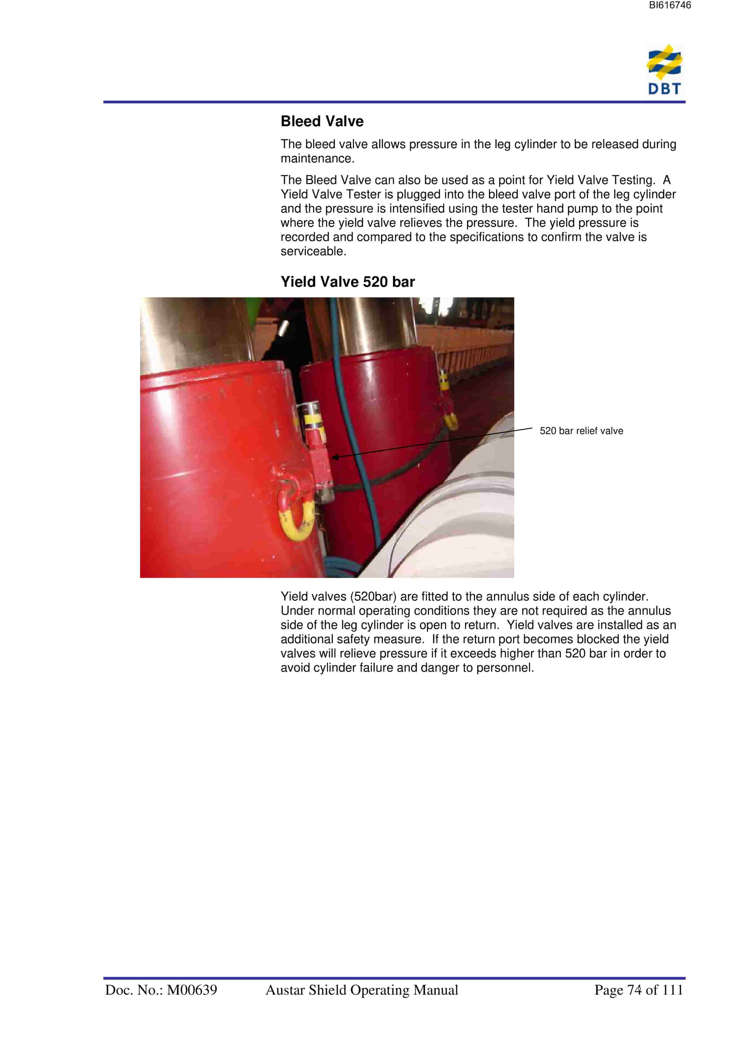
- 1.6.5.4. Yield Valve 520 bar
- 1.6.6. Base Lift Cylinder Circuit
- 1.6.7. Power Take-off Connection Points
- 1.6.8. Manual Hydraulic Controls
- 1.6.8.1. Control Unit
- 1.7. Shield Control System
- 1.7.1. AUTOMATIC
- 1.7.2. Major Key Functions
- 1.7.2.1. Stop Key Function
- 1.7.2.2. Emergency Stop Button Function
- 1.7.2.3. Local Lockout Button Function
- 1.7.3. PMC-R Operating Modes
- 1.7.3.1. Idle Mode
- 1.7.3.2. Work Mode
- 1.7.3.3. Input Mode
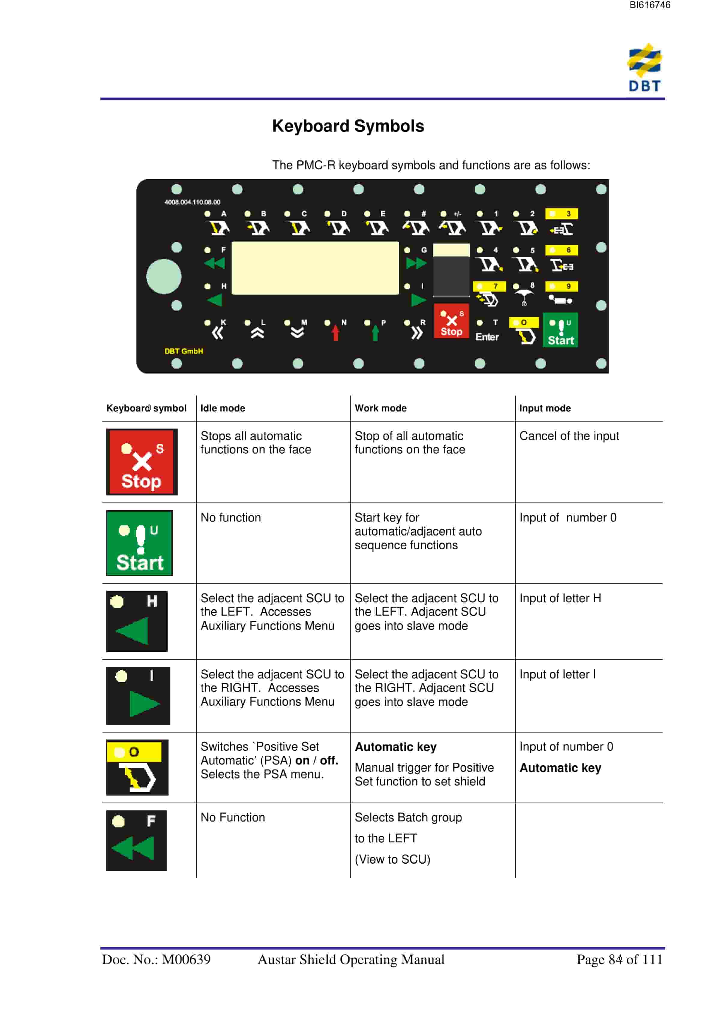
- 1.7.4. Keyboard Symbols
- 1.7.4.1. PMC-R Menu Structure
- 1.7.5. Austar PMC-R Menu headlines
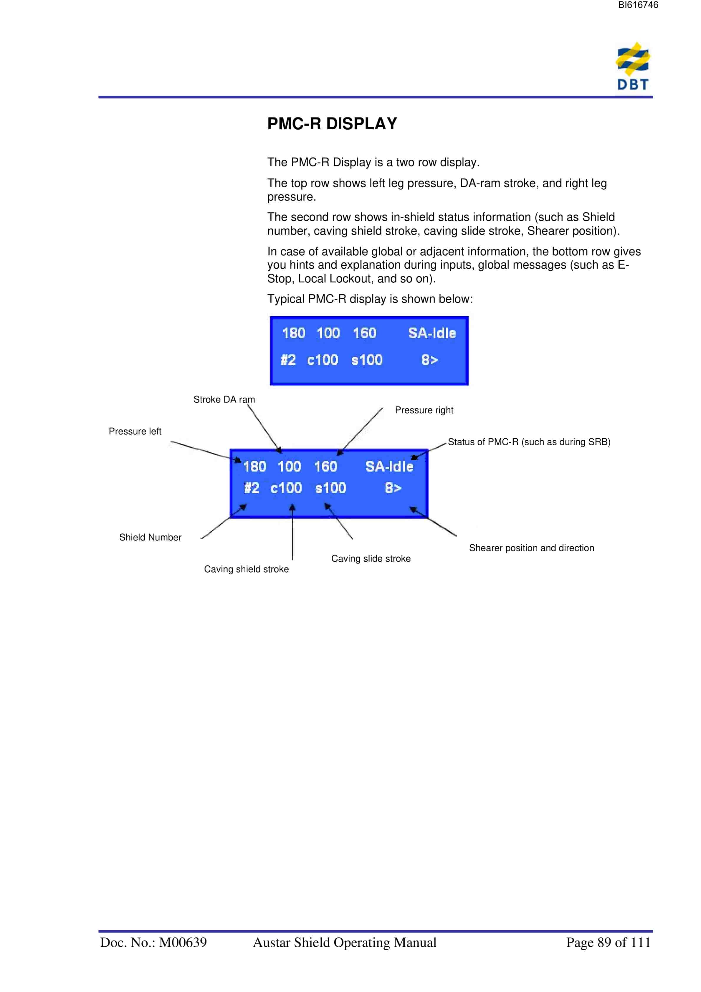
- 1.7.6. PMC-R DISPLAY
- 1.7.6.1. Master/Slave
- 1.7.6.2. Display of E-STOP Event
- 1.7.7. Shield Control Methods
- 1.7.8. Six Methods of Shield Control
- 1.7.9. Start Shearer Running Batch SRB
- 1.7.9.1. NEWSTART
- 1.7.9.2. RESTART
- 1.7.9.3. SRB Serial Mode
- 1.7.9.4. SRB Manual Mode
- 1.7.10. Reversing the Shearer
- 1.7.11. Travel Zone
- 1.7.11.1. Travel Zone Operation
- 1.7.12. Auto Sequence (Support Advance)
- 1.7.13. Gate Shield Sequence
- 1.7.14. Roadway Shield Sequence
- 1.7.15. Adjacent Control Function
- 1.7.16. Auxiliary Functions
- 1.7.17. Remote Operation
- 1.7.18. In Shield Caving Functions
- 1.7.19. Start a Batch Function (Support Advance Sequence)
- 1.7.20. Start a Bankpush – AFC Advance (Front-Conveyor)
- 1.7.21. Types of Bankpush
- 1.7.21.1. (S) Snake
- 1.7.21.2. (T) Taper
- 1.7.21.3. (All) All
- 1.7.22. Protection Zones
- 1.7.23. Selecting a Bankpush Range
- 1.7.24. Start a Bankpull – AFC Advance (REAR-CONVEYOR)
- 1.7.25. Start Conveyor Pullback (Front Conveyor)
- 1.7.26. Start Top Coal Caving (TCC)
- 1.7.27. Positive Set Function
- 1.7.27.1. Guaranteed Set
- 1.7.27.2. High Pressure Set
- 1.7.27.3. Disabling Positive Set
Related products
-
Bucyrus Belt System Spare Parts List 316102 – 318743
$30.00 Add to cart -
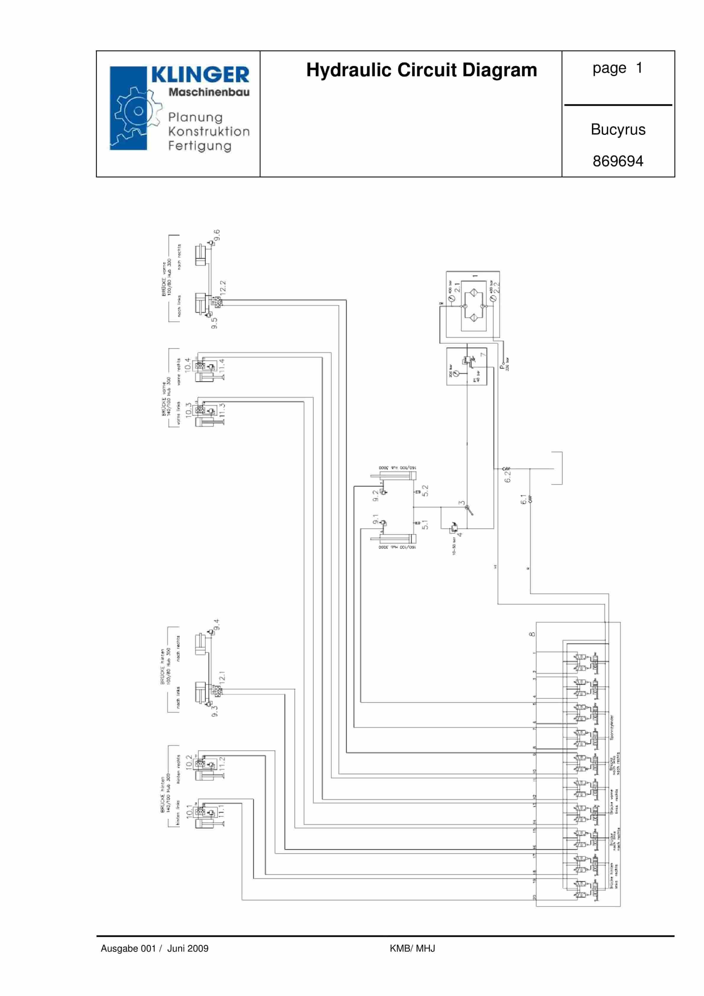
Bucyrus Hydraulic Circuit Diagram Service Parts List 869694
$30.00 Add to cart -
Bucyrus Conveyor Steering Device Technical Description 7427 078 000 BA 00
$30.00 Add to cart -
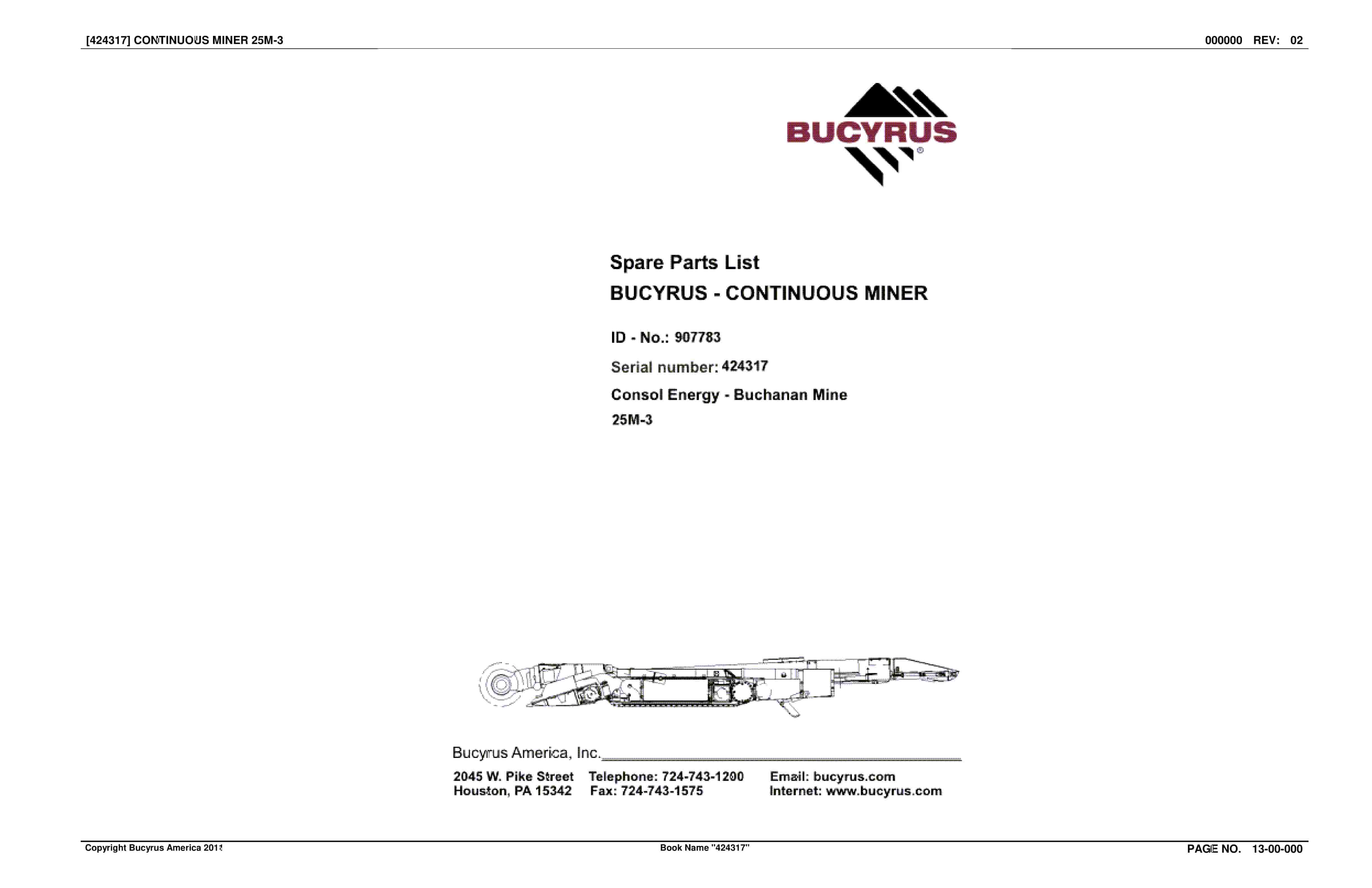
Bucyrus Continuous Miner Spare Parts List 907783
$30.00 Add to cart -
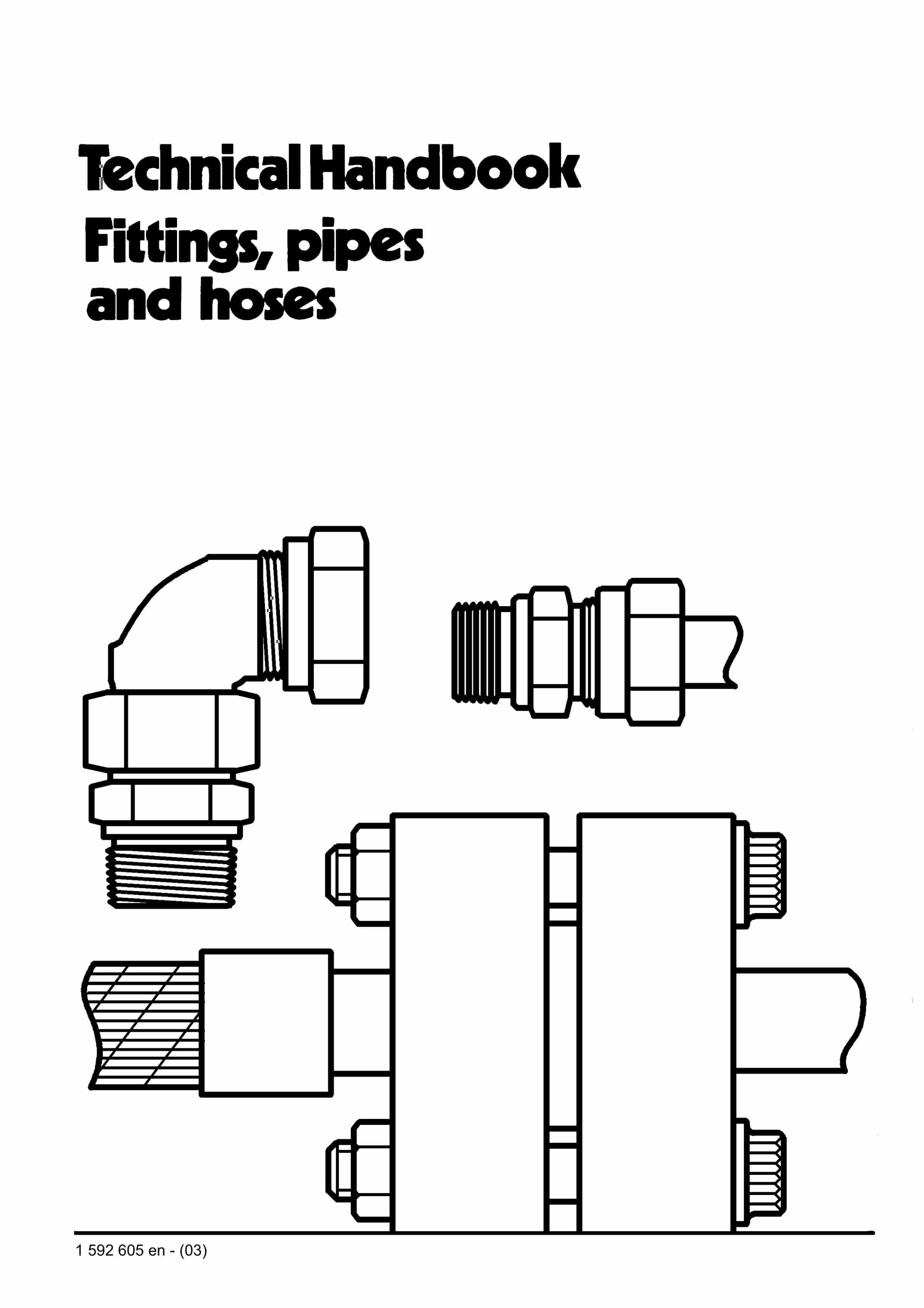
Bucyrus Fittings, Pipes And Hoses Technical Handbook 1592605
$30.00 Add to cart


