

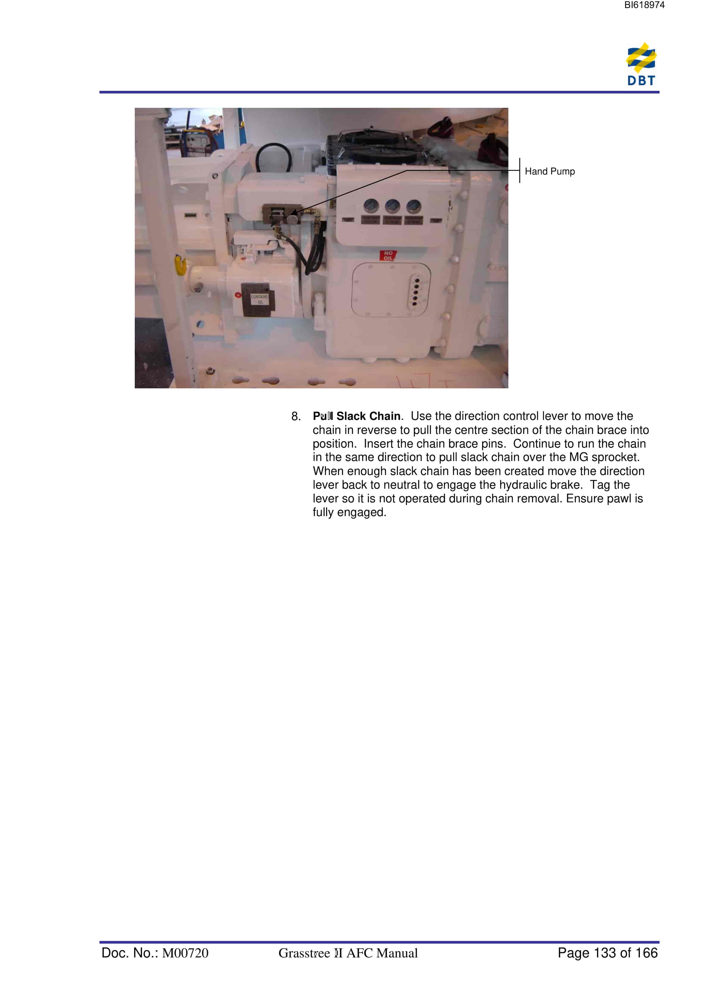
Bucyrus Grasstree II AFC Technical Manual BI618974
$30.00
- Type Of Manual: Technical Manual
- Manual ID: BI618974
- Number of Pages: 167
- Size: 5.9MB
- Format: PDF
Product details
-
Model List:
- Grasstree II AFC
- 1. M00720.pdf
- 1.1. General Safety
- 1.1.1. Personnel
- 1.1.1.1. Operation
- 1.1.1.2. Installation and repair
- 1.1.2. Operating conditions
- 1.1.2.1. Intended use
- 1.1.2.2. Unauthorised use
- 1.1.3. Safety instructions
- 1.1.3.1. General rules
- 1.1.3.2. Noise emissions
- 1.1.3.3. Condition
- 1.1.3.4. Safety equipment
- 1.1.3.5. Information signs
- 1.1.3.6. Emergency-stop
- 1.1.3.7. Block working area
- 1.1.3.8. Moving parts
- 1.1.4. Storage and Transport
- 1.1.4.1. Transport safety device
- 1.1.4.2. Lifting Equipment
- 1.1.4.3. Floor conveying device
- 1.1.5. Erection and commissioning
- 1.1.5.1. Inclined storage
- 1.1.5.2. Environmental acceptability
- 1.1.6. Operation
- 1.1.6.1. Moving conveyor
- 1.1.7. Maintenance and repair
- 1.1.7.1. Original parts
- 1.1.7.2. Release of walking legs
- 1.1.7.3. Lifting the conveyor
- 1.1.7.4. Safety equipment
- 1.1.8. Hydraulics
- 1.1.8.1. Handling of Hydraulic Fluids
- 1.1.8.2. Maintenance and Repair
- 1.1.8.3. Permissible Hoses
- 1.1.8.4. Installation of Hydraulic Hoses
- 1.2. Storage and transport
- 1.2.1. Storage
- 1.2.1.1. Corrosion protection
- 1.2.1.2. No direct exposure to sunlight
- 1.2.1.3. Dirt and moisture
- 1.2.1.4. Short-term storage
- 1.2.1.5. Long-term storage
- 1.2.1.6. Plastic deformation
- 1.2.1.7. Random sample inspection
- 1.2.1.8. Natural ageing
- 1.2.1.9. HFA fluids
- 1.2.2. Transport
- 1.2.2.1. Load units dimensions and weights
- 1.2.3. Before transport
- 1.2.3.1. Temperatures below freezing
- 1.2.3.2. Electrical and electronic components
- 1.2.4. Transport of the components
- 1.2.4.1. Machine parts
- 1.3. Introduction
- 1.3.1. Functions and Purpose of AFC
- 1.3.2. General Data and Information
- 1.4. Major components of AFC
- 1.4.1. Maingate Drive
- 1.4.2. Maingate Drive Module
- 1.4.2.1. kW Water Cooled Motor
- 1.4.2.2. Cooling Water
- 1.4.2.3. Hydraulic Slow Run Device
- 1.4.3. MRKR 45/1100/1500 Maingate Drive Frame
- 1.4.3.1. Drive Sprocket
- 1.4.3.2. BSL Return Sprocket
- 1.4.3.3. Maingate Drive Auto-greasing
- 1.5. Tailgate Drive
- 1.5.1. Tailgate Drive Module
- 1.5.1.1. Cooling Water
- 1.5.1.2. Hydraulic Slow Run Device
- 1.5.2. MRHS-45/PF5-1142 Tensionable Tailgate Driveframe
- 1.5.2.1. Tensioning Controls
- 1.5.2.2. Drive Sprocket
- 1.5.2.3. Tailgate Drive Auto-Greasing
- 1.6. Gradient Pans
- 1.6.1. Installing Bolted Dogbone Connectors
- 1.7. AFC PF5/1242 Pan Line
- 1.7.1. Line Pans
- 1.7.2. Inspection pans
- 1.7.2.1. Inspection Door Removal Procedure
- 1.7.3. Rerouting Pans
- 1.7.4. Mid-face Pans
- 1.7.5. Spillplates
- 1.7.6. Dogbone
- 1.7.7. Importance of Alignment and Butting of Pans during Installat
- 1.7.8. Threading the Bottom Race
- 1.7.9. Cleaning the Bottom Race
- 1.7.10. Pan Weight
- 1.8. AFC Chain Assembly
- 1.8.1. AFC Chain
- 1.8.1.1. AFC Chain Connectors
- 1.8.2. Wollbrecht AFC Chain Brace
- 1.8.3. AFC Flights
- 1.8.4. Correct Orientation of Chain
- 1.8.5. AFC Chain Ramp (optional)
- 1.8.6. Chain Puller Attachment (optional)
- 1.8.7. Jumbotrack Shearer Haulage
- 1.9. AFC Operation
- 1.9.1. Setting Chain Tension Manually
- 1.9.2. Batch Push Recommendations
- 1.9.3. AFC Snake
- 1.9.4. Cutting beyond the Tailgate Drive
- 1.9.5. Clearing AFC Blockages
- 1.9.6. Reversing the AFC
- 1.10. Carry-Out Start, Stop and Shut-down Procedures
- 1.10.1. Normal Start Procedure
- 1.10.2. Temporary Stop
- 1.10.3. Normal Shut Down
- 1.11. Chain Tensioning System Components Operation
- 1.11.1. Overview
- 1.11.2. Chain Tensioning System Components
- 1.11.2.1. TG Drive Frame
- 1.11.2.2. Reed Rod
- 1.11.2.3. Pressure Sensor
- 1.11.2.4. Solenoid Driver
- 1.11.2.5. PM-4 Unit
- 1.11.2.6. Manual Controls
- 1.12. PMC-D System
- 1.12.1. Keyboard Functions
- 1.12.2. PMC- D System Start Sequence
- 1.12.3. PMC-D Operating Errors/Warnings
- 1.12.3.1. Stored Error Messages
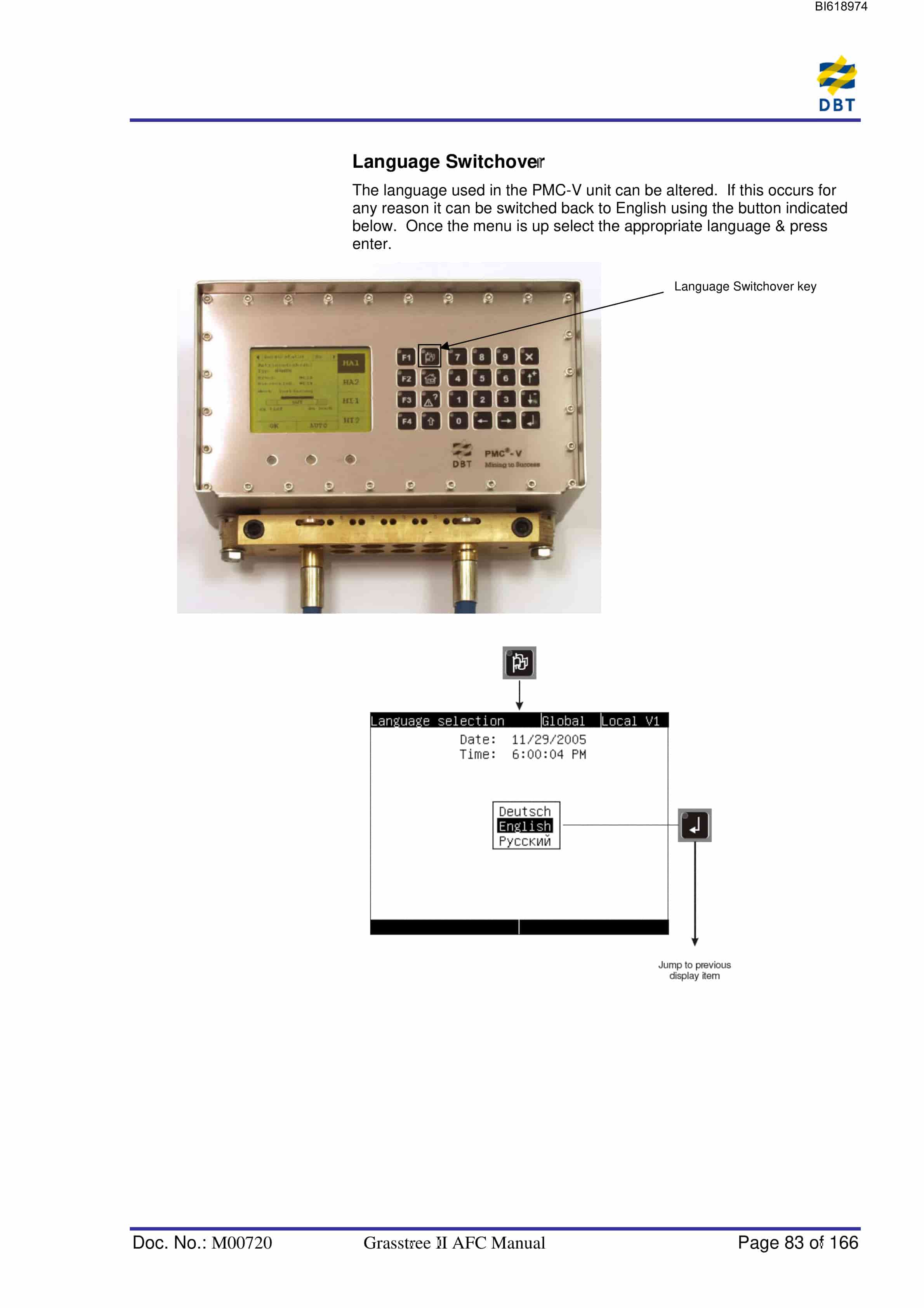
- 1.12.3.2. Language Switchover
- 1.12.3.3. Start Menu
- 1.12.4. CST Operating Modes
- 1.12.4.1. Selecting Operating Mode
- 1.12.4.2. Automatic Mode
- 1.12.4.3. Semi-automatic Mode
- 1.12.4.4. Inspection Mode
- 1.12.4.5. Emergency Mode
- 1.12.4.6. Emergency Manual Mode
- 1.12.5. Resetting the PMC-D System
- 1.12.5.1. Resetting a RED alarm
- 1.12.5.2. Resetting a YELLOW alarm
- 1.12.6. PMC-D Operating Errors/Warnings
- 1.12.6.1. Chain Tensioner
- 1.12.6.2. Cooling Oil Temperature
- 1.12.6.3. Hydraulic Filter
- 1.12.6.4. System Pressure
- 1.12.6.5. Cooling Oil Pressure
- 1.12.6.6. Input Speed (Blockade Overload)
- 1.12.6.7. Output Speed (Blockade)
- 1.12.6.8. Overload
- 1.12.6.9. PMC-D Communication Errors
- 1.12.6.10. Current Measurement
- 1.12.7. Changing AFC running modes
- 1.12.7.1. Inspection Mode
- 1.12.7.2. Changing to Emergency Mode
- 1.12.7.3. Changing to Emergency Manual Mode (Slow Runner Mode)
- 1.12.7.4. AFC Reverse Procedure
- 1.13. PMC-D Faults
- 1.13.1. PMC-D message/errors
- 1.13.2. Sensor Errors
- 1.13.3. Changing a PMC-D/V Unit
- 1.13.4. PMC-D Display Error List
- 1.13.4.1. The Start Sequence of the CST system (Auto Mode)
- 1.13.5. Major components of CST (Controlled Start Transmission) Syst
- 1.13.6. CST Hydraulic Control
- 1.13.6.1. Constant system pressure
- 1.13.6.2. Filtration
- 1.13.7. CST Hydraulic Pressure Control during PMC-D controlled modes
- 1.13.7.1. Automatic
- 1.13.7.2. Emergency Mode Operation
- 1.13.7.3. Emergency Manual Mode Operation
- 1.13.8. PMC-D Control Loops
- 1.13.8.1. Pressure control
- 1.13.8.2. Slip control
- 1.13.8.3. Load balancing
- 1.13.8.4. Full Automatic
- 1.13.8.5. Semi Automatic
- 1.14. CST Trouble Shooting
- 1.14.1. Overview
- 1.14.2. The CST Gearbox Connections
- 1.15. Chain Tensioning System Components Operation
- 1.15.1. Operating Modes
- 1.15.1.1. CTS Operation Starting Automatic Operation
- 1.15.1.2. CTS Operation Stopping Automatic Manual Operations
- 1.15.1.3. Manual Functions
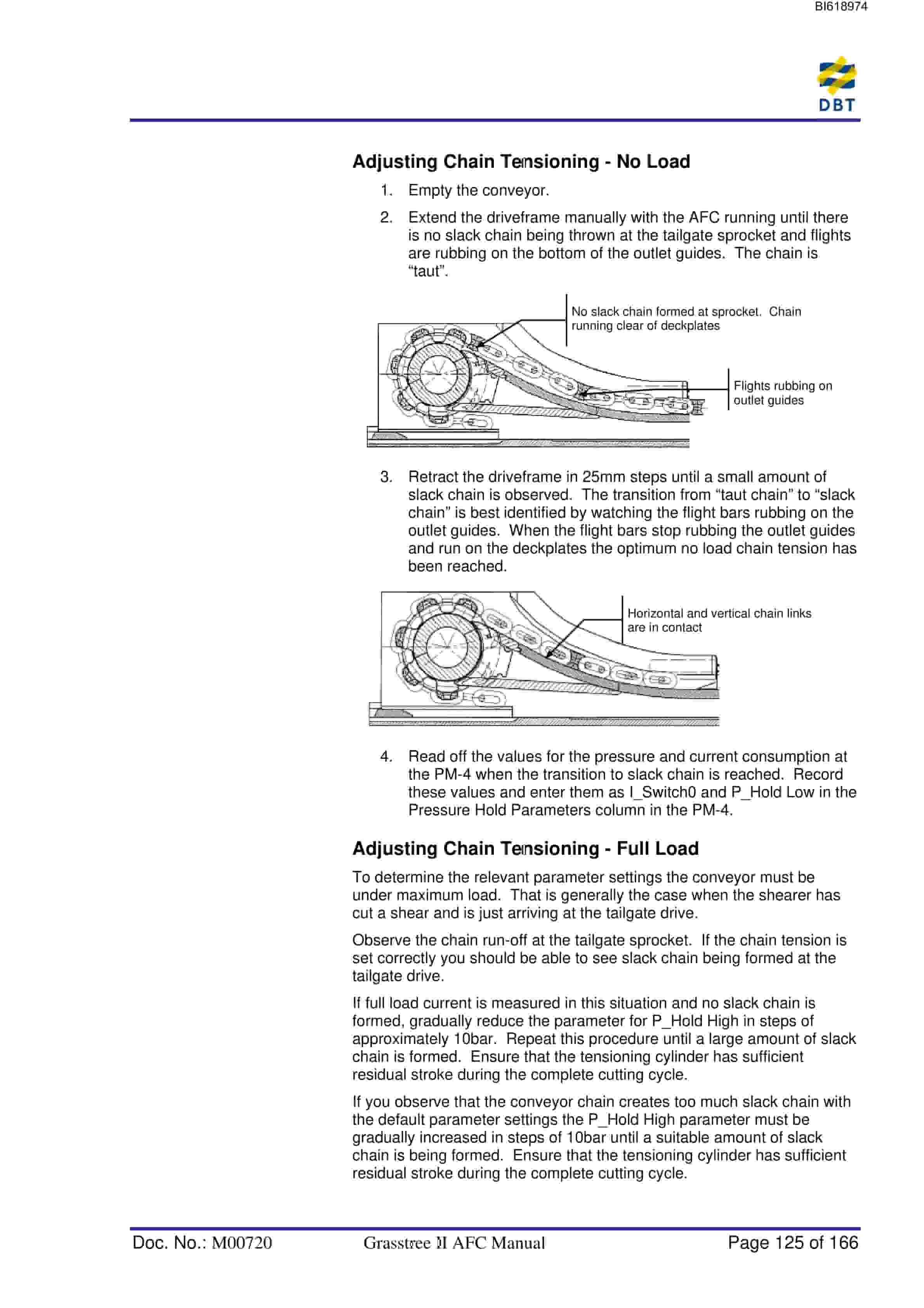
- 1.15.1.4. Adjusting Chain Tensioning – No Load
- 1.15.1.5. Adjusting Chain Tensioning – Full Load
- 1.15.2. AFC Reverse Procedure
- 1.16. AFC Maintenance
- 1.16.1. Lubrication
- 1.16.1.1. Approved Lubricants
- 1.16.2. Chain Assembly
- 1.16.2.1. Flights
- 1.16.3. TG Drive Wear Plates
- 1.16.4. Sprockets Chain Strippers, Tongue Plates
- 1.16.5. Relief Valve
- 1.16.6. Wollbrecht AFC Chain Brace
- 1.16.7. Using Slowrunners for Chain Replacement
- 1.16.8. Dogbone Replacement Procedure
- 1.16.9. Inspection Doors Removal Procedure
- 1.16.10. Jumbotrack Rackbar Replacement Procedure
- 1.16.11. AFC Greasing
- 1.17. Gearbox Maintenance
- 1.17.1. Overview
- 1.17.2. P-45, Maingate Oil Levels and Quantities
- 1.17.3. KP-45,Maingate and Tailgate Oil Levels and Quantities
- 1.17.4. Gearbox Breather Replacement Procedure
- 1.18. Common Faults Fault Finding Methods
- 1.18.1. PMC-D shuts down CST and shows Blockage Conveyor
- 1.18.2. PMC-D shuts down on an Oil Temperature High Error 125
- 1.18.3. PMC-D shuts down CST on a Filter Differential Pressure High
- 1.18.4. CST shuts down and PMC-V shows a System Pressure Low Error
- 1.18.5. PMC-D shuts down CST on a Cooling Oil Pressure Low Error 1
- 1.18.6. The Clutch Pressure Control is Erratic or Slow
- 1.18.7. The Clutch Pressure Sensor is not Working Correctly
- 1.18.8. PMC-D shuts down the CST on an Input/Output Speed Sensor or
- 1.18.9. CST shuts down and PMC-D shows Overload Motor Current Erro
- 1.18.10. CST shuts down and PMC-D shows Chain Tensioner
- 1.18.11. The Gearbox Leaks Oil
Related products
-
Bucyrus Gleithobel Plow Outrigger Steering System Technical Description 1999 001 027 BA 00
$30.00 Add to cart -
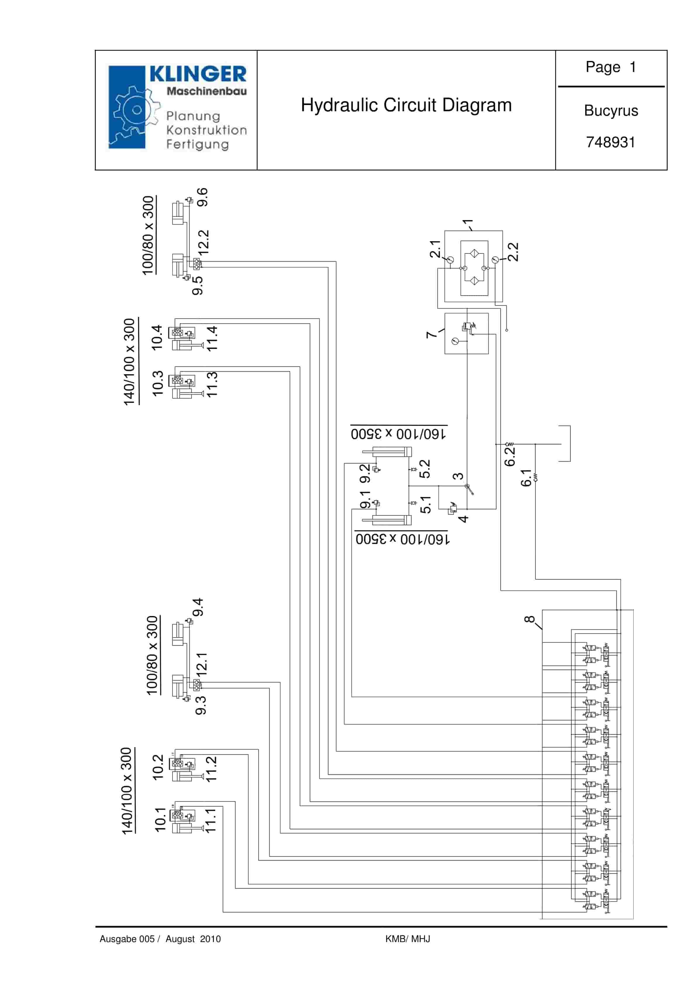
Bucyrus Hydraulic Circuit Diagram Service Parts List 748931
$30.00 Add to cart -
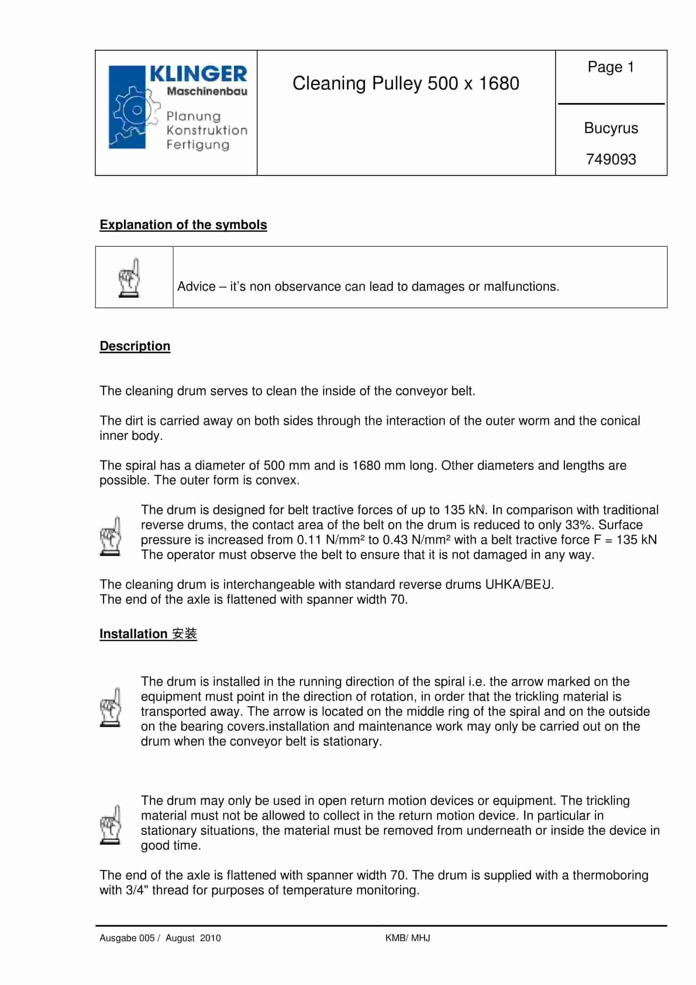
Bucyrus Cleaning Pulley 500 x 1680 Service Parts List 749093
$30.00 Add to cart -
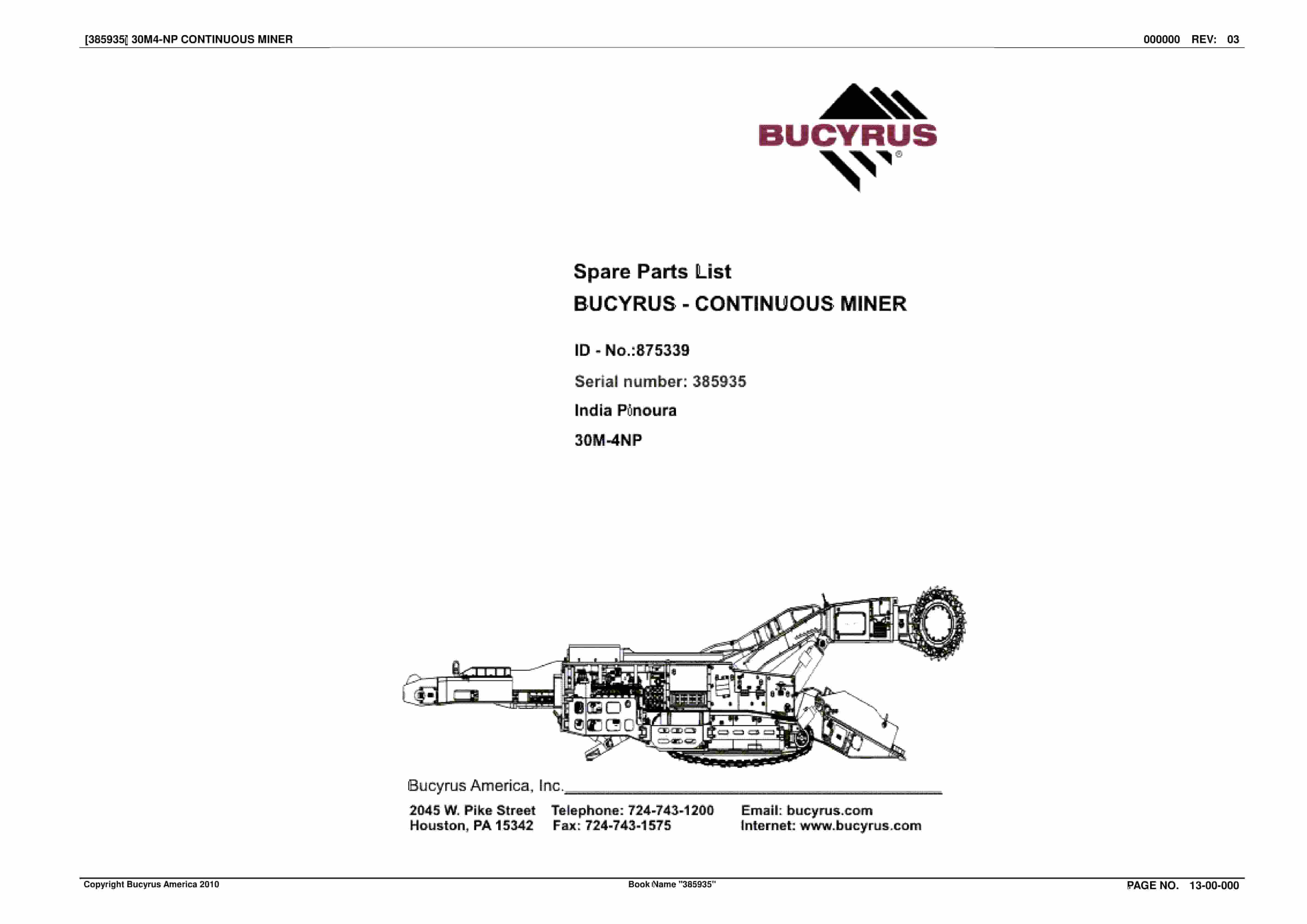
Bucyrus Continuous Miner Spare Parts List 875339
$30.00 Add to cart -
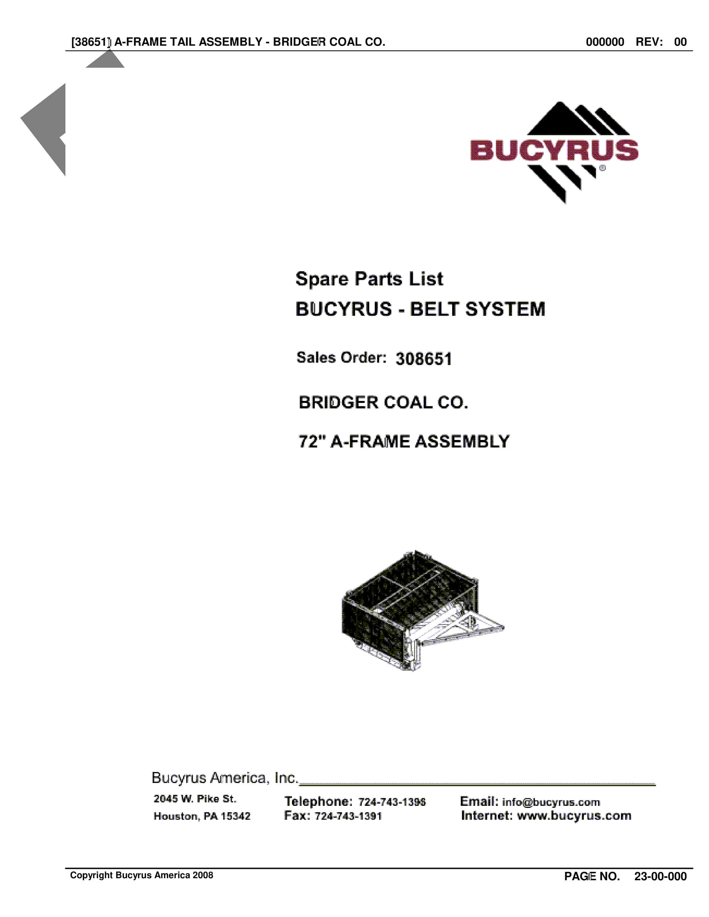
Bucyrus Belt System Spare Parts List 308651
$30.00 Add to cart


