

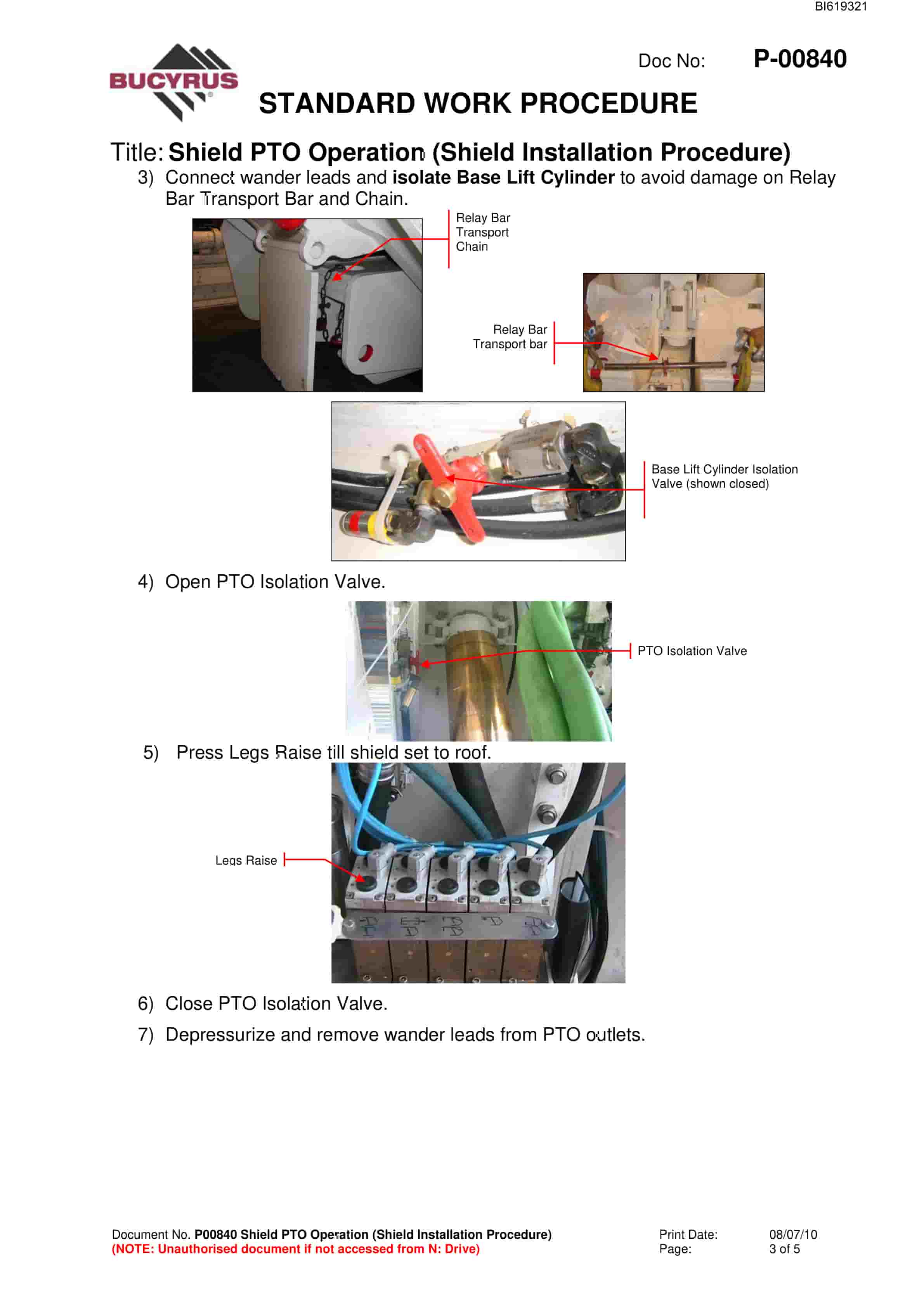
Bucyrus Grasstree Shields Technical Manual BI619321
$30.00
- Type Of Manual: Technical Manual
- Manual ID: BI619321
- Number of Pages: 142
- Size: 3.2MB
- Format: PDF
Product details
-
Model List:
- Grasstree Shields
- 1. M01278.pdf
- 1.1. M01278 Grasstree Shields Maintenance Procedures Contents
- 1.2. P00821 KN Valve Replacement
- 1.3. P00822 Relay Bar Replacement
- 1.4. P00823 Stabilising Cylinder Yield Valve Replacement
- 1.5. P00824 Stablising Cylinder Replacement
- 1.6. P00825 Reed Rod Replacement
- 1.7. P00826 Advancing Cylinder Replacement
- 1.7.1. Advancing Cylinder Replacement
- 1.7.2. Safety Instructions
- 1.7.3. PROCEDURE
- 1.7.4. Electrical Isolation. Push in the lockout button on the support control unit (SCU).
- 1.7.5. Depressurise Ring Side of Advancing Cylinder. Press the support advance button to depressurise the ring side of the advancing cylinder.
- 1.7.6. Hydraulic Isolation. Isolate the support from the 350 bar pressure supply using the isolation valve.
- 1.7.7. Relieve Hydraulic Pressure. Dissipate pressure by operating the manual hydraulic control buttons for support advance. Ensure pressure has been relieved by twisting the relief valve.
- 1.7.8. Disconnect Cables Hoses. Disconnect the SKK24 cable from the cylinder port.
- 1.7.9. Disconnect Hoses. Twist hoses to ensure pressure has been dispated. Disconnect the pressure and return hoses from the cylinder.
- 1.7.10. Remove Front Locking Bracket. Undo bolts and remove the locking pieces from the advancing cylinder clevis at the front of the cylinder.
- 1.7.11. Pull Relay Bar Assembly to Face. Attach a chain block to a lifting point and using a strap lift the advancing cylinder so it is clear of the bridge. Using chainblock pull relay bar assembly forwards till the rear pin can be accessed from between the pontoons (under walkway).
- 1.7.12. Remove Rear Locking Pin. Remove the retaining clip and locking pin from the advancing cylinder clevis at the rear and of the relay bar. Access is possible between the support pontoons.
- 1.7.13. Lift Remove Advancing Cylinder. Attach a chain block and strap to support the advancing cylinder from the canopy lifting point. Attach another lifting device to manouvre the cylinder out of the support.
- 1.7.14. Install Replacement Cylinder. Reverse the procedure to manouvre the replacement cylinder into position over the relay bar.
- 1.7.15. Locate Cylinder in Rear Slots of Relay Bar. Using the chain block lower the rear of the cylinder into the slots on the relay bar.
- 1.7.16. Replace Rear Locking Pins. Replace the rear locking pins in the clevis at the rear of the relay bar.
- 1.7.17. Attach to Front Mounting Clevis. Push relay bar assembly to goaf till cylinder can be lowered into front mounting clevis. Lower the cylinder into the front mounting bracket and reinstall the locking pieces.
- 1.7.18. Reattach Hoses and SKK24 Cable. Reattach hydraulic hoses and the SKK24 reed rod cable.
- 1.7.19. Replace Baselift Cylinder. Replace baselift cylinder and attach hydraulic hoses removed from same.
- 1.7.20. Remove Hydraulic and Electrical Isolation. Slowly open the isolation valve. Pull out the black lockout button on the SCU.
- 1.7.21. Test for Correct Function. Operate the relevant hydraulic buttons to test the cylinder for correct operation.
- 1.7.22. COMMENTS / CHANGES REQUIRED
- 1.8. P00827 Advancing Cylinder Yield Valve Replacement
- 1.8.1. Advancing Cylinder Yield Valve Replacement
- 1.8.2. Safety Instructions
- 1.8.3. PROCEDURE
- 1.8.4. Confirm Safe to Start. Confirm with the section official that it is safe to carry out this job.
- 1.8.5. Electrical Isolation. Push in the lockout button on the support control unit (SCU).
- 1.8.6. Depressurise Ring Side of Advancing Cylinder. Press the support advance button to depressurise the ring side of the advancing cylinder.
- 1.8.7. Hydraulic Isolation. Isolate the support from the hydraulic pressure supply using the isolation valve on the supply manifold.
- 1.8.8. Relieve Hydraulic Pressure. Dissipate pressure by operating the manual hydraulic control buttons for support advance. Ensure pressure has been relieved by twisting the relief valve.
- 1.8.9. Remove Yield Valve. Remove the staple retaining the yield valve and remove the valve.
- 1.8.10. Replace Yield Valve. Install the replacement valve and replace staple.
- 1.8.11. Remove Hydraulic and Electrical Isolation. Slowly open the isolation valve. Pull out the black lockout button on the SCU.
- 1.8.12. Test for Correct Function. Operate the advancing cylinder to test the circuit for correct operation.
- 1.8.13. COMMENTS / CHANGES REQUIRED
- 1.9. P00828 Backflush Filter Replacement
- 1.9.1. Backflush Filter Replacement
- 1.9.2. PROCEDURE
- 1.9.3. Confirm Safe to Start. Confirm with the section official that it is safe to carry out this job.
- 1.9.4. Electrical Isolation. Push in the lockout button on the support control unit (SCU).
- 1.9.5. Hydraulic Isolation. Isolate the support from the hydraulic pressure supply using the isolation valve on the supply manifold.
- 1.9.6. Relieve Hydraulic Pressure. Dissipate pressure by operating the manual hydraulic control buttons. Check pressure has been relieved by operating hydraulic buttons on main valve block.
- 1.9.7. Remove Filter Assembly. Remove staples retaining filter assemblies. Pull each filter assembly from the block.
- 1.9.8. Replace Filter. Unscrew filter cartridge (left hand tread) from filter assembly base. Replace filter cartridge. Check O-rings for damage and replace if necessary.
- 1.9.9. Replace Filter Assembly. Replace filter assembly and retaining staple.
- 1.9.10. Remove Hydraulic and Electrical Isolation. Slowly open the isolation valve. Pull out the black lockout button on the SCU.
- 1.9.11. Test Filter Function. Operate the backflush filter manual handles to test both chambers of the filter are operating correctly.
- 1.9.12. COMMENTS / CHANGES REQUIRED
- 1.10. P00829 Base Cylinder Replacement
- 1.10.1. Safety Instructions
- 1.10.2. PROCEDURE
- 1.10.3. Confirm Safe to Start. Confirm with the section official that it is safe to carry out this job.
- 1.10.4. Electrical Isolation. Push in the lockout button on the support control unit (SCU).
- 1.10.5. Hydraulic Isolation. Isolate the support from the hydraulic pressure supply using the isolation valve on the supply manifold.
- 1.10.6. Check Baselift Circuit is Depressurised. Operate the manual buttons for the baselift cylinder to relieve any pressure in piston and annulus sides of the circuit.
- 1.10.7. Disconnect Hoses. Twist hoses to ensure pressure has been dissipated. Disconnect the pressure and return hoses from the cylinder..
- 1.10.8. Remove Cover Bracket. Remove staples and pins from the top cover of the baselift cylinder. slide the baselift cover towards face.
- 1.10.9. Slide cylinder. Lift the cylinder and slide it up. When the cylinder reaches the end of sliding path slide it towards the face.
- 1.10.10. Remove Cylinder. Manouvre cylinder from support.
- 1.10.11. Install Replacement Cylinder. Lift the replacement cylinder into the shield using chain blocks. Install hoses.
- 1.10.12. Remove Hydraulic Isolation. Slowly open the isolation valve.
- 1.10.13. Remove Electrical Isolation. Pull out the black lockout button on the SCU.
- 1.10.14. Test the Cylinder Function.
- 1.10.15. COMMENTS / CHANGES REQUIRED
- 1.11. P00830 Control Block Filter Replacement
- 1.11.1. Safety Instructions
- 1.11.2. PROCEDURE
- 1.11.3. Confirm Safe to Start. Confirm with the section official that it is safe to carry out this job.
- 1.11.4. Electrical Isolation. Push in the lockout button on the support control unit (SCU).
- 1.11.5. Hydraulic Isolation. Isolate the support from the hydraulic pressure supply using the isolation valve on the supply manifold.
- 1.11.6. Relieve Hydraulic Pressure. Dissipate pressure by operating the manual hydraulic control buttons.
- 1.11.7. Remove Filter. Unscrew filter to remove from control block.
- 1.11.8. Replace Filter. Install the replacement or cleaned filter.
- 1.11.9. Remove Hydraulic and Electrical Isolation. Slowly open the isolation valve. Pull out the black lockout button on the SCU.
- 1.11.10. Check Control Block Function. Using a neighbouring shield, operate shield on adjacent control to check functions are operating correctly.
- 1.11.11. COMMENTS / CHANGES REQUIRED
- 1.12. P00831 Control Block Pilot Non-Return Valve Replacement
- 1.12.1. Control Block Pilot Non-Return Valve Replacement
- 1.12.2. Safety Instructions
- 1.12.3. PROCEDURE
- 1.12.4. Confirm Safe to Start. Confirm with the section official that it is safe to carry out this job.
- 1.12.5. Electrical Isolation. Push in the lockout button on the support control unit (SCU).
- 1.12.6. Hydraulic Isolation. Isolate the support from the hydraulic pressure supply using the isolation valve on the supply manifold.
- 1.12.7. Relieve Hydraulic Pressure. Dissipate pressure by operating the manual hydraulic control buttons.
- 1.12.8. Remove pilot non-return valve. Unscrew pilot non-return valve to remove from control block.
- 1.12.9. Replace pilot non-return valve. Install the replacement pilot non-return valve.
- 1.12.10. Replace Control Blocks. Replace control blocks if moved to access pilot non-return valve.
- 1.12.11. Remove Hydraulic and Electrical Isolation. Slowly open the isolation valve. Pull out the black lockout button on the SCU.
- 1.12.12. Check Control Block Function. Using a neighbouring shield, operate shield on adjacent control to check functions are operating correctly.
- 1.12.13. COMMENTS / CHANGES REQUIRED
- 1.13. P00832 Double Solenoid Pilot Valve Replacement
- 1.13.1. Double Solenoid Pilot Valve
- 1.13.2. Safety Instructions
- 1.13.3. PROCEDURE
- 1.13.4. Confirm Safe to Start. Confirm with the section official that it is safe to carry out this job.
- 1.13.5. Electrical Isolation. Push in the lockout button on the support control unit (SCU).
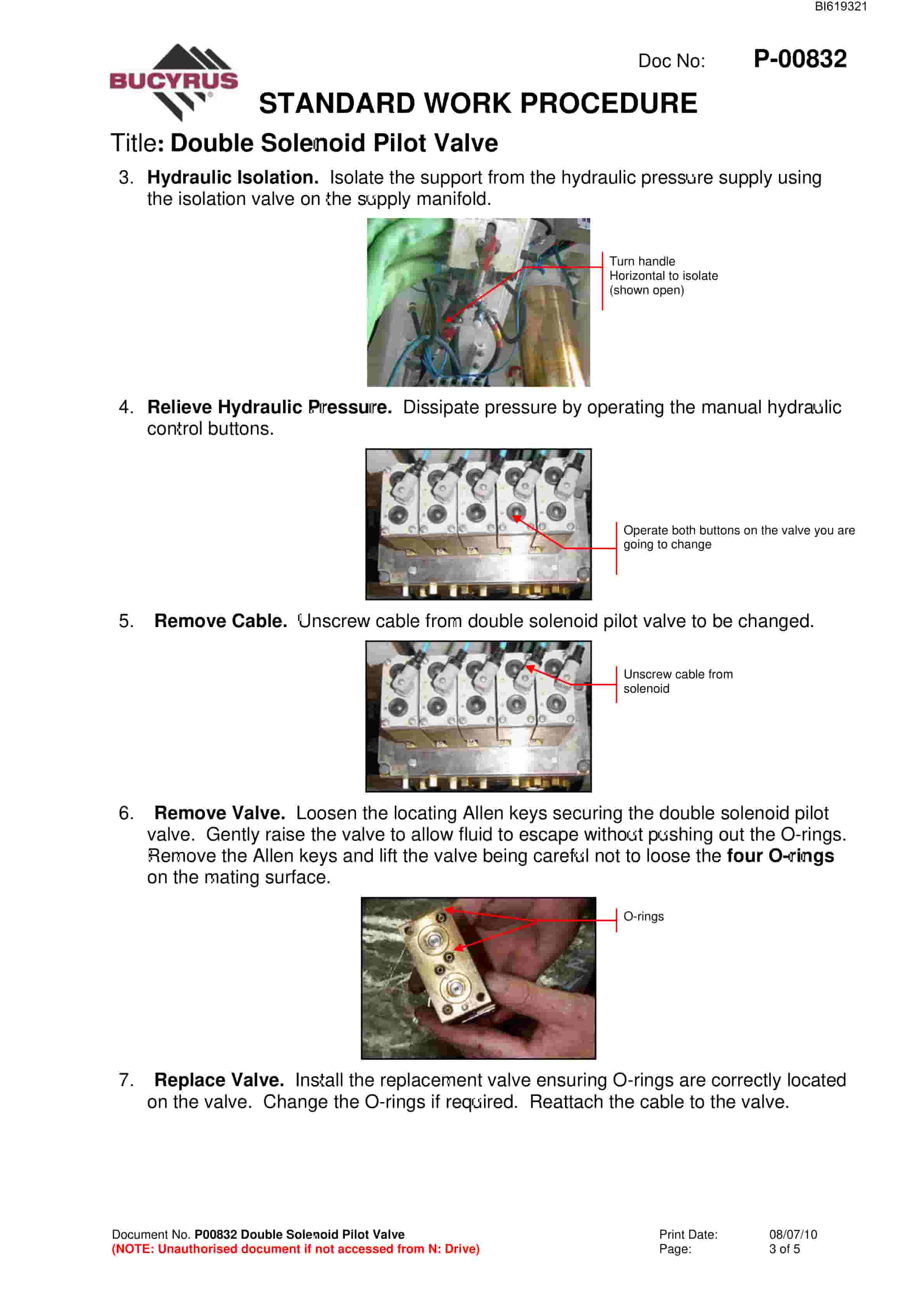
- 1.13.6. Hydraulic Isolation. Isolate the support from the hydraulic pressure supply using the isolation valve on the supply manifold.
- 1.13.7. Relieve Hydraulic Pressure. Dissipate pressure by operating the manual hydraulic control buttons.
- 1.13.8. Remove Cable. Unscrew cable from double solenoid pilot valve to be changed.
- 1.13.9. Remove Valve. Loosen the locating Allen keys securing the double solenoid pilot valve. Gently raise the valve to allow fluid to escape without pushing out the O-rings. Remove the Allen keys and lift the valve being careful not to loose the four O-rings on the mating surface.
- 1.13.10. Replace Valve. Install the replacement valve ensuring O-rings are correctly located on the valve. Change the O-rings if required. Reattach the cable to the valve.
- 1.13.11. Remove Hydraulic and Electrical Isolation. Slowly open the isolation valve. Pull out the black lockout button on the SCU
- 1.13.12. Test Valve Function. Operate the relevant hydraulic buttons to test the valve is operating correctly.
- 1.13.13. COMMENTS / CHANGES REQUIRED
- 1.14. P00833 Hydraulic Hose Replacement
- 1.14.1. Hydraulic Hose Replacement
- 1.14.2. Safety Instructions
- 1.14.3. Follow Mine safety procedures.
- 1.14.4. PROCEDURE
- 1.14.5. Confirm Safe to Start. Confirm with the section official that it is safe to carry out this job.
- 1.14.6. Electrical Isolation. Push in the lockout button on the support control unit (SCU).
- 1.14.7. Hydraulic Isolation. Isolate the support from the hydraulic pressure supply using the isolation valve on the supply manifold.
- 1.14.8. Relieve Hydraulic Pressure. Dissipate pressure by operating the manual hydraulic control buttons.
- 1.14.9. Note If the hose is in the advancing cylinder circuit you will have to use the manual hydraulic control buttons for the relevant functions to relieve pressure that may be locked in the hose by the POCVs in the manifolds.
- 1.14.10. Ensure pressure has been relieved by twisting the hose and checking pressure gauge readings where applicable.
- 1.14.11. Remove Worn Hose. Remove staple lock and pull hose from fitting.
- 1.14.12. Fit New Hose. Fit new hose and replace staple lock pins. Ensure hose and staples are correctly fitted.
- 1.14.13. Remove Hydraulic and Electrical Isolation. Slowly open the isolation valve. Pull out the black lockout button on the SCU.
- 1.14.14. Test Hose Function. Operate the relevant function to test the hose is correctly fitted and there are no leaks.
- 1.14.15. COMMENTS / CHANGES REQUIRED
- 1.15. P00834 Isolation Adaptor Replacement
- 1.15.1. Staple Puller
- 1.15.2. Safety Instructions
- 1.15.3. PROCEDURE
- 1.15.4. Remove staple.
- 1.15.5. Pull out cable and protect against dirt. Note which cables are connected to each socket of the isolation adaptor to make installation easier.
- 1.15.6. Unbolt location bolts.
- 1.15.7. Remove Isolation Adaptor.
- 1.15.8. Install new Isolation Adaptor and tighten bolts.
- 1.15.9. Install cables to the Isolation Adaptor. Note the red socket of the isolation adaptor is connected to the emergency stop button end Bi-Di port of the SCU.
- 1.15.10. Check if system has re-powered.
- 1.15.11. Remove old Isolation Adaptor to surface for cleaning and repair.
- 1.15.12. COMMENTS / CHANGES REQUIRED
- 1.16. P00835 Leg Cylinder Yield Valve Replacement
- 1.16.1. Safety Instructions
- 1.16.2. PROCEDURE
- 1.16.3. Confirm Safe to Start. Confirm with the section official that it is safe to carry out this job.
- 1.16.4. Electrical Isolation. Push in the lockout button on the support control unit (SCU).
- 1.16.5. Remove Leg POCV Cover. Remove locking pins on both sides and lift the cover.
- 1.16.6. Isolate Leg Cylinder. Isolate the leg cylinder with the good yield valve with the red isolation valve on the leg cylinder manifold. The leg being isolated is the leg with the good yield valve.
- 1.16.7. Depressurise Piston Side of Leg Cylinder. Press the legs lower button to depressurise the piston side of the leg cylinder with the faulty pressure gauge. The leg with the good yield valve remains set to the roof as it has been isolated.
- 1.16.8. Hydraulic Isolation. Isolate the support from the hydraulic pressure supply using the isolation valve on the supply manifold.
Related products
-
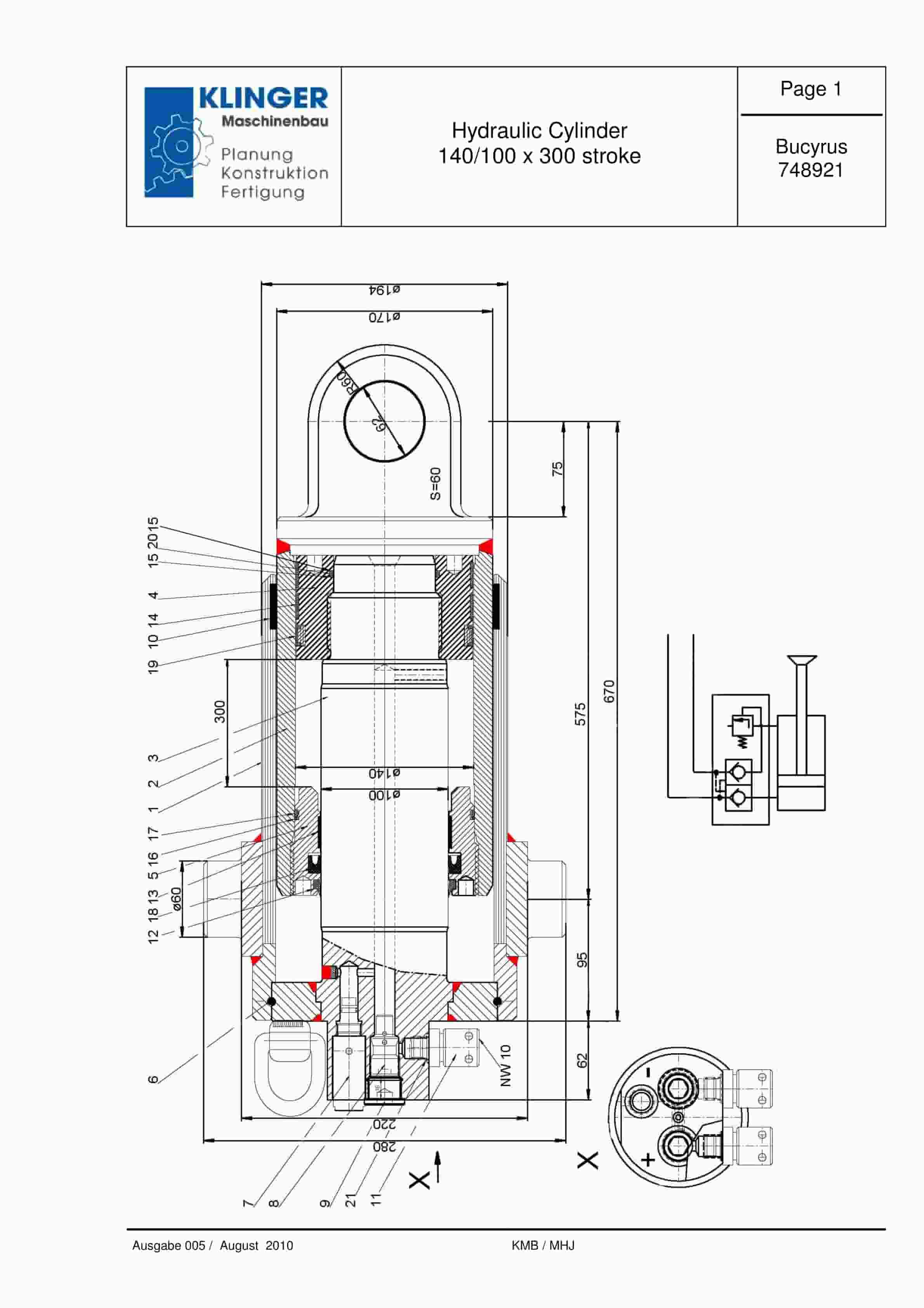
Bucyrus Hydraulic Cylinder 140-100 x 300 Stroke Service Parts List 748921
$30.00 Add to cart -
Bucyrus Belt System Spare Parts List 316102 – 318743
$30.00 Add to cart -
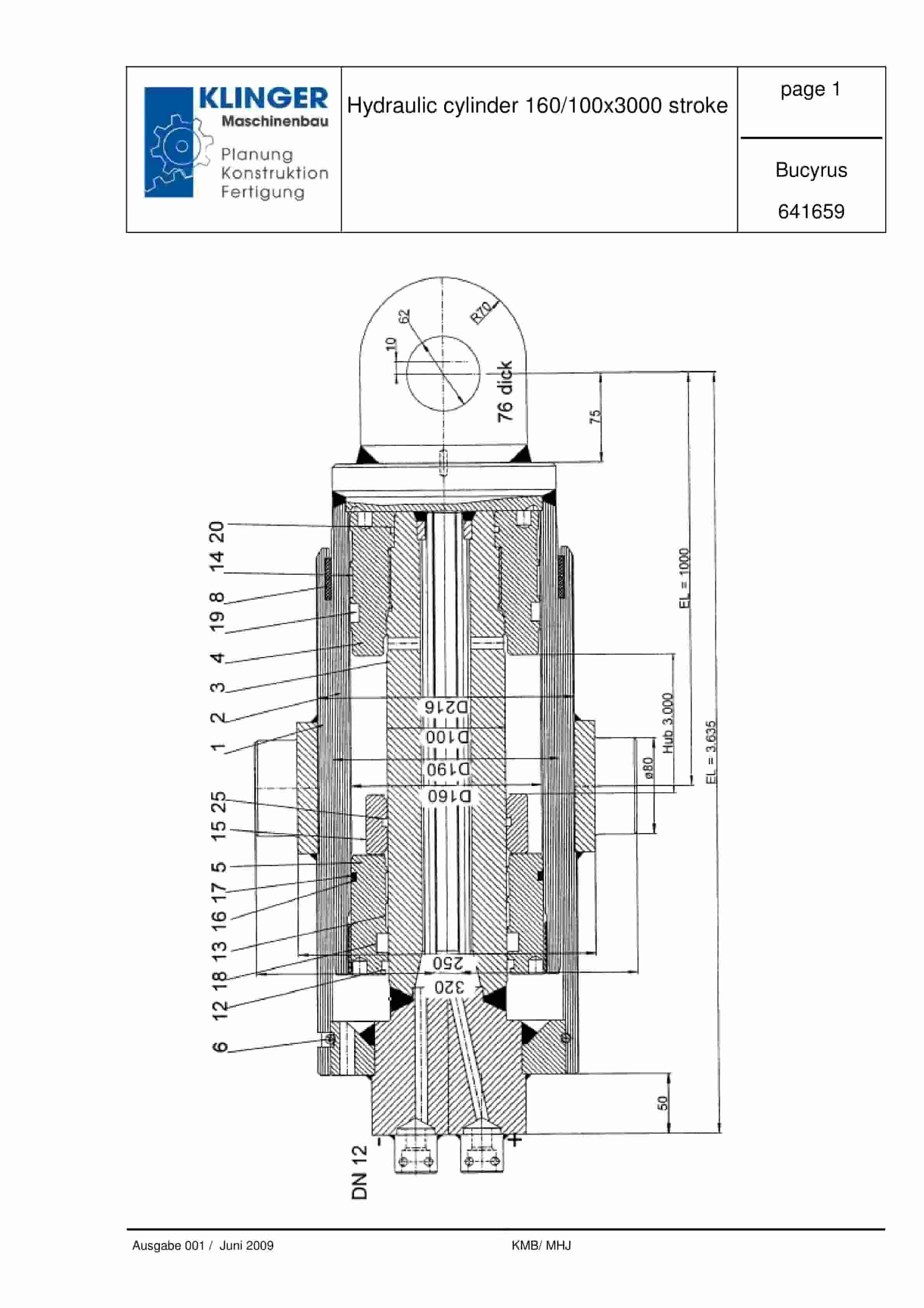
Bucyrus Hydraulic Cylinder 160-100 x 3000 Stroke Service Parts List 641659
$30.00 Add to cart -
Bucyrus Belt System Spare Parts List 203106
$30.00 Add to cart -

Bucyrus Fundamentals Of Electrical Engineering Technical Handbook 2440049
$30.00 Add to cart


