

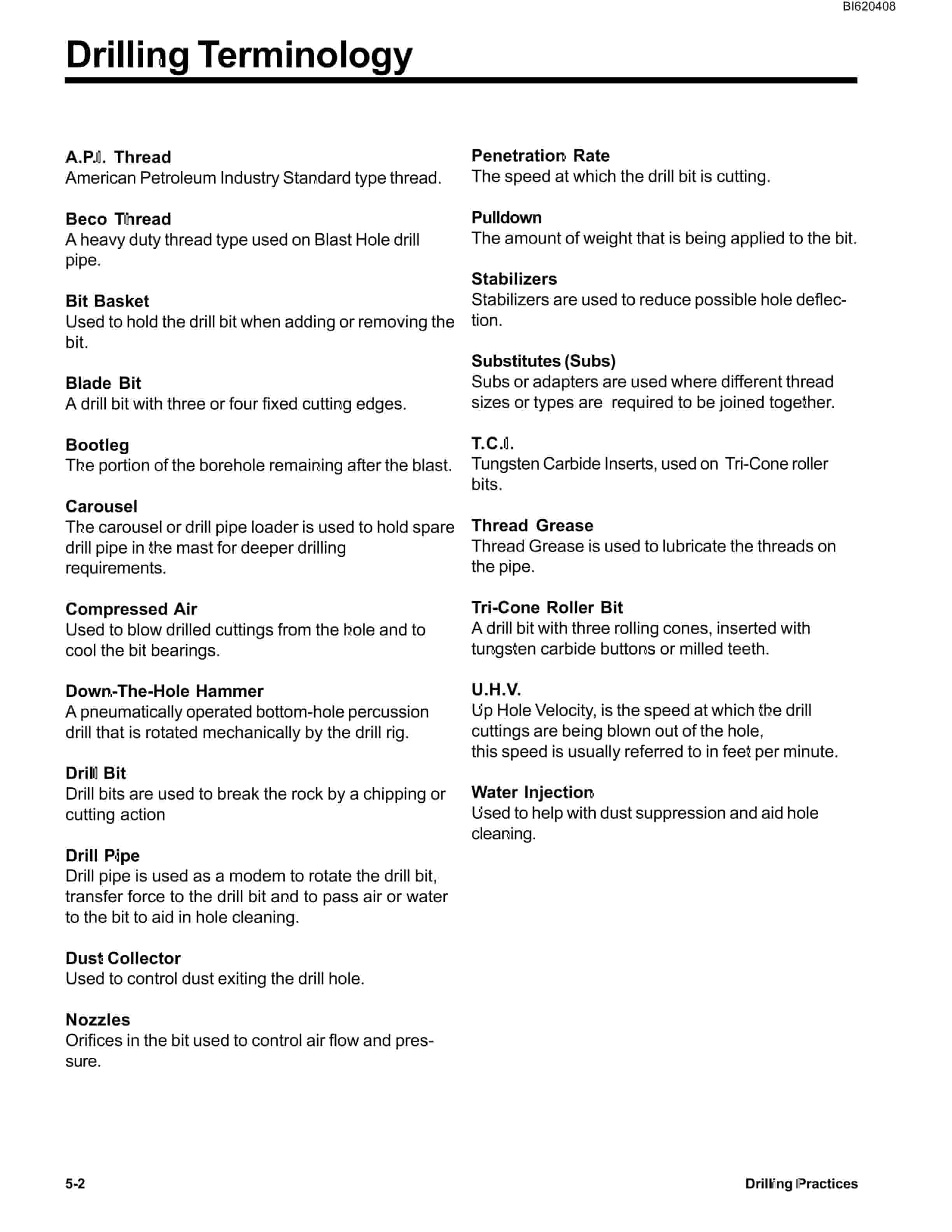
Bucyrus SKF-12 Infinity Blasthole Drill Technical Manual BI620408
$30.00
- Type Of Manual: Technical Manual
- Manual ID: BI620408
- Number of Pages: 131
- Size: 9.4MB
- Format: PDF
Product details
-
Model List:
- SKF-12 Infinity Blasthole Drill
- 1. SKF-12 Operators manual-E74.pdf
- 1.1. Introduction
- 1.2. Parts Ordering and Product Support
- 1.3. Product Description
- 1.4. SKF-12 Component Locator
- 1.5. Table of Contents
- 1.6. Section 1-SAFETY
- 1.6.1. Overview of Potential Hazards
- 1.6.1.1. Before Operation
- 1.6.1.2. Clearances from Overhead High Voltage Lines
- 1.6.1.3. Operation
- 1.6.1.4. After Operation
- 1.6.1.5. Maintenance
- 1.6.1.6. Equipment Transfer
- 1.7. Section 2-OPERATORS CONTROLS
- 1.7.1. Graphic Symbol Legend
- 1.7.2. Warning Decals
- 1.7.3. Operator Control Panel (standard)
- 1.7.4. System Pressure Gauge Panel
- 1.7.5. Switch Panel (standard)
- 1.7.6. Lights, Circuit Breakers PLC Screen
- 1.7.7. Vigilante System Operation
- 1.7.7.1. Description and Operation
- 1.7.7.2. PLC Touch Screen Display
- 1.7.7.3. Drill Mode Screen
- 1.7.7.4. Laser Depth system
- 1.7.7.4.1. Functional Description of Operation
- 1.7.7.4.2. Pipe in Hole Detection
- 1.7.7.5. Tram Mode Screen
- 1.7.7.6. Menu Screen
- 1.7.7.7. Password Protected Screens
- 1.7.7.8. Gauge Screen
- 1.7.7.9. Hammer Oil Screen
- 1.7.7.10. Alarm Screen
- 1.7.7.11. Alarm History Screen
- 1.7.7.12. Information Screen
- 1.7.8. Air Conditioner
- 1.7.8.1. Operating Instructions
- 1.7.8.2. Fan Speed Switch
- 1.7.8.3. Mode Switch
- 1.7.8.4. Thermostat
- 1.7.8.5. Supply Air
- 1.7.9. Cab Heater
- 1.7.9.1. Cab Heater Fault Isolation
- 1.7.10. Operators Seat
- 1.8. Section 3-LUBRICATION AND PREVENTIVE MAINTENANCE
- 1.8.1. Service Points – SKF-12
- 1.8.2. Lubrication Maintenance Chart
- 1.8.3. Lubrication – General
- 1.8.4. Lubrication – Compressor Winch
- 1.8.5. Lubricant Specifications
- 1.8.5.1. Hydraulic System
- 1.8.5.2. Hydraulic Tank Capacity
- 1.8.6. Preventive Maintenance
- 1.8.6.1. Hydraulic System Maintenance
- 1.8.6.2. Cooling System Maintenance
- 1.8.6.3. Cooling System Freeze Protection
- 1.8.6.4. Air Cleaners
- 1.8.6.5. Air Filter Elements
- 1.8.6.6. Electrical System
- 1.8.6.7. Scheduled Oil Sampling Analysis
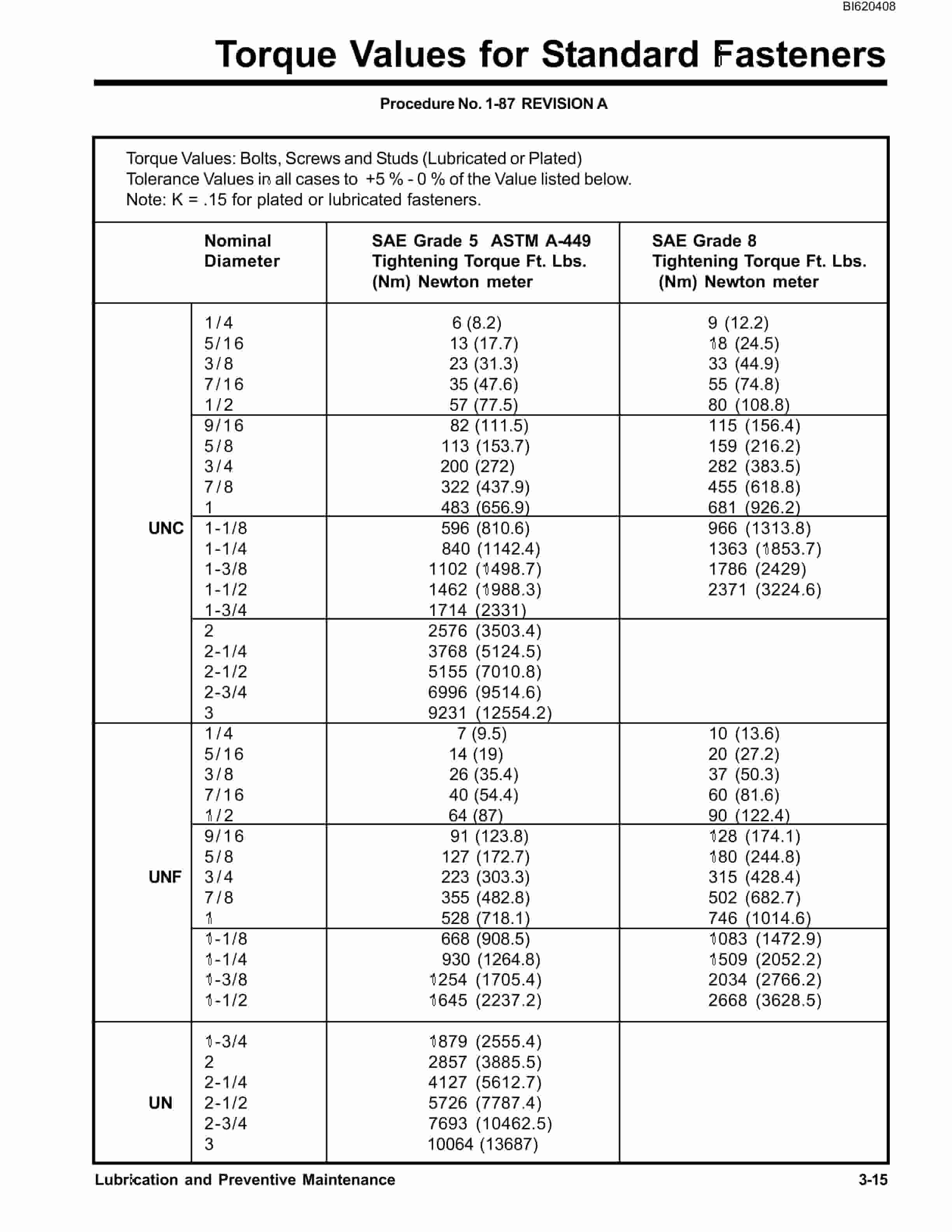
- 1.8.7. Torque Values for Standard Fasteners
- 1.8.8. Torque Values for Split Flange Connections
- 1.8.9. Torque Values for Hydraulic Tubes Fittings
- 1.9. Section 4-OPERATING INSTRUCTIONS
- 1.9.1. Pre-Start Checks
- 1.9.1.1. Commissioning A New Machine
- 1.9.1.2. Pre-Start Checklist
- 1.9.2. Normal Start-Up Procedure
- 1.9.2.1. To Start Engine
- 1.9.2.2. After Start Checks
- 1.9.2.3. Normal Shut Down
- 1.9.3. Emergency Shutdown
- 1.9.4. Cold Weather Operation
- 1.9.4.1. Hydraulic System Warm-Up
- 1.9.4.2. Compressor Warm-Up (Low Pressure)
- 1.9.4.3. Compressor Warm-Up (High Pressure)
- 1.9.5. Propelling Machine
- 1.9.6. Leveling Machine
- 1.9.6.1. Raising Machine (lowering jacks)
- 1.9.6.2. Lowering Machine (raising jacks)
- 1.9.7. Re-Leveling Machine
- 1.9.7.1. Leveling Procedure
- 1.9.7.2. Re-Leveling Procedure
- 1.9.8. Raising Mast
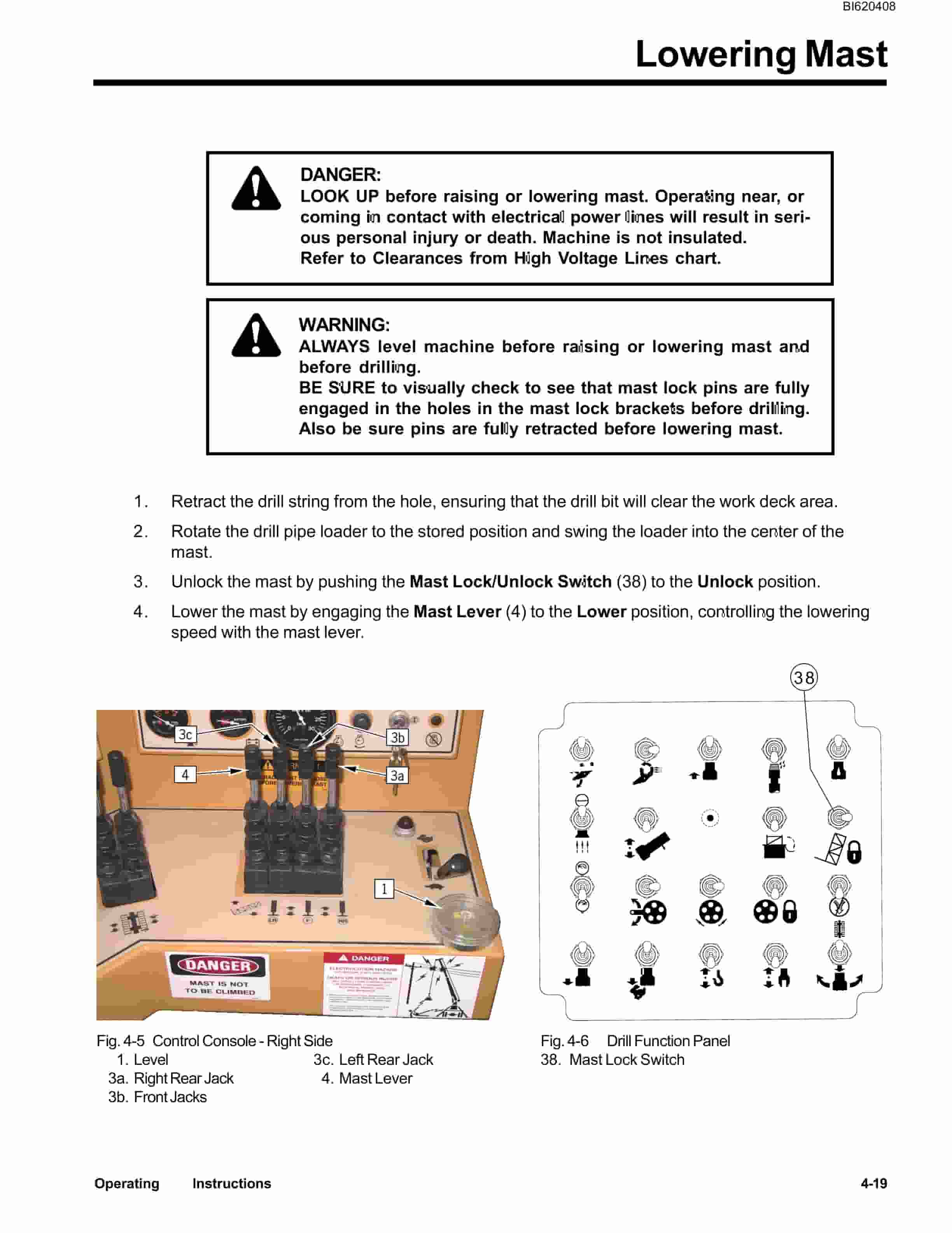
- 1.9.9. Lowering Mast
- 1.9.10. Loading Drill Pipe
- 1.9.11. Preparing to Drill
- 1.9.11.1. Installing and Removing Drill Bit
- 1.9.12. Drilling Procedures
- 1.9.12.1. Drilling with Standard Bit
- 1.9.12.2. Drilling with a Down The Hole Hammer
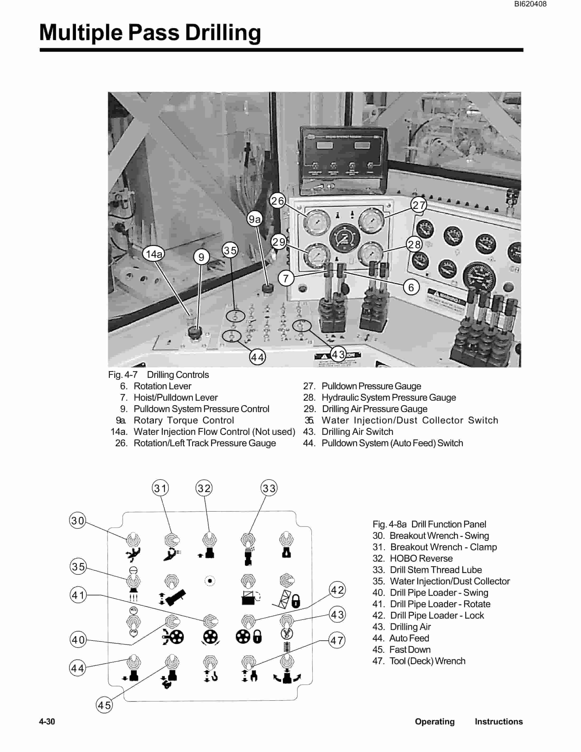
- 1.9.13. Multiple Pass Drilling
- 1.9.13.1. Adding Drill Pipe
- 1.9.14. Retracting Drill Pipe
- 1.10. Section 5-DRILLING PRACTICES
- 1.10.1. Drilling Terminology
- 1.10.2. Bit Weight Rotary Speeds
- 1.10.3. Rotary Drill Bits
- 1.10.3.1. Tri-Cone Roller Bits
- 1.10.4. Rotary Blast Hole Drill Strings
- 1.10.4.1. Drill Pipe
- 1.10.4.2. Pipe Threads
- 1.10.4.3. Regular Threads
- 1.10.4.4. BECO Threads
- 1.10.4.5. Thread Grease
- 1.10.4.6. Substitutes
- 1.10.5. Drill Bit Stabilizers
- 1.10.6. Compressed Air
- 1.10.6.1. Air Requirements
- 1.10.6.2. Up-Hole Velocity Calculations
- 1.10.7. Drilling Related Problems
- 1.10.8. Operating Problems and Indicators
- 1.10.9. Solving Drilling Problems
- 1.11. Section 6-MACHINE TRANSPORT AND SPECIFICATIONS
- 1.11.1. Transporting Machine
- 1.11.1.1. Mast Removal and Installation
- 1.11.1.2. Loading and Unloading of Machine
- 1.11.1.3. Loading and Unloading of Mast
- 1.11.2. Transient Stability Limits
- 1.11.3. Metric Conversions
Related products
-
Bucyrus Belt System Spare Parts List 308651
$30.00 Add to cart -
Bucyrus Continuous Miner Spare Parts List 373608
$30.00 Add to cart -
Bucyrus Continuous Miner Spare Parts List 907783
$30.00 Add to cart -
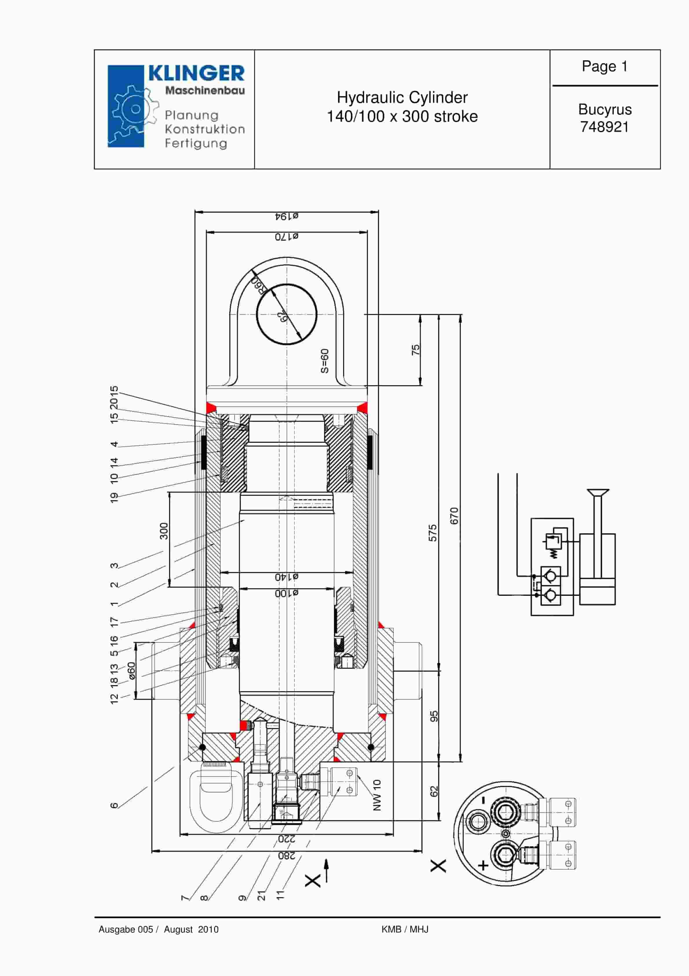
Bucyrus Hydraulic Cylinder 140-100 x 300 Stroke Service Parts List 748921
$30.00 Add to cart -
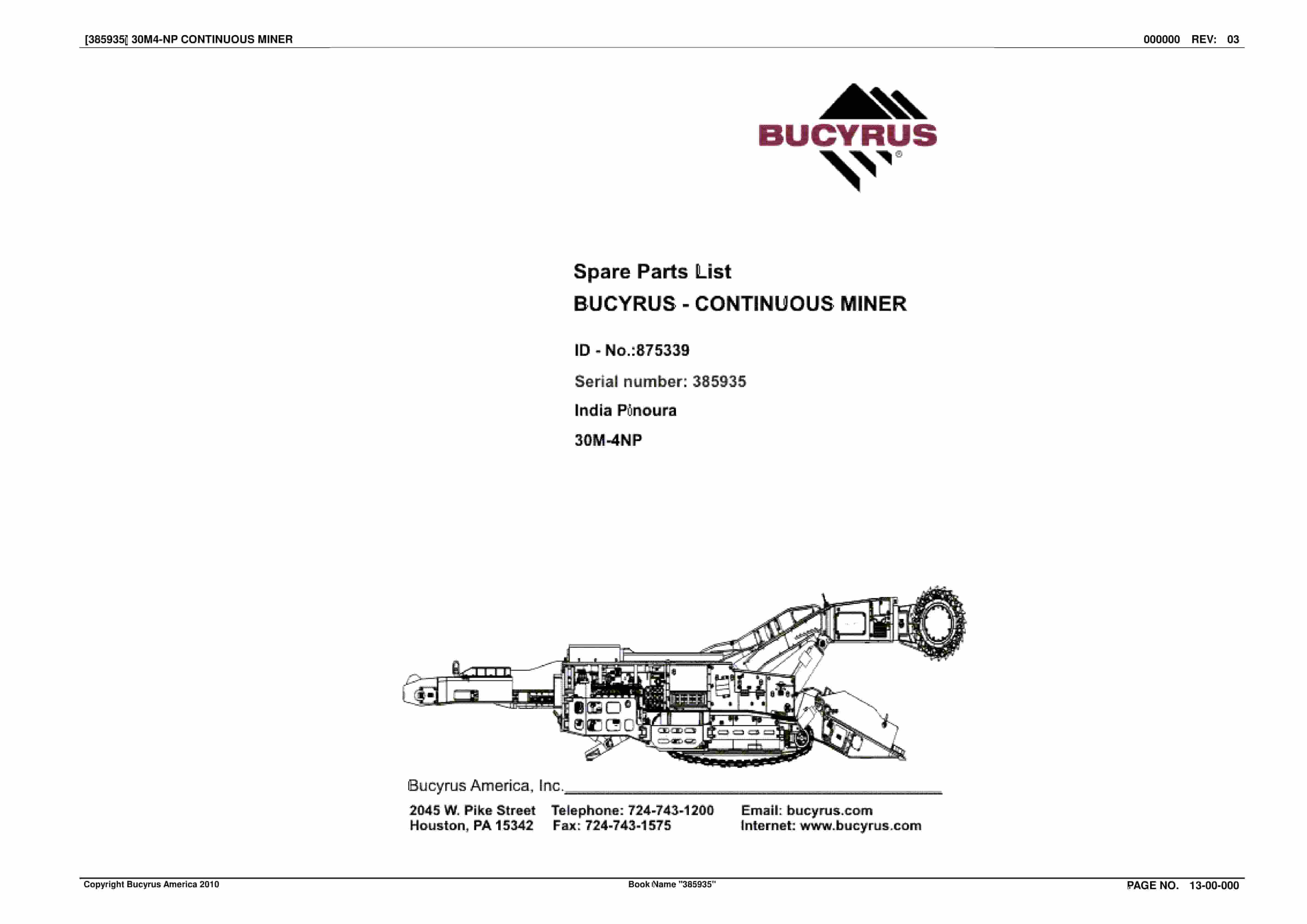
Bucyrus Continuous Miner Spare Parts List 875339
$30.00 Add to cart


