

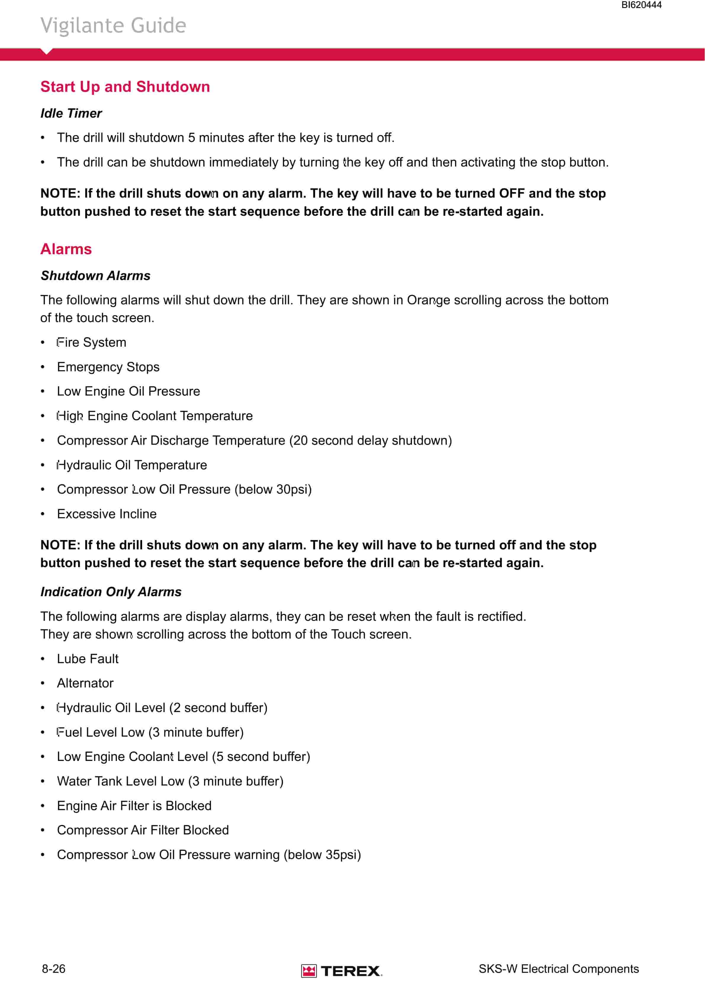
Bucyrus SKS-W Infinity Blasthole Drill Technical Manual BI620444
$30.00
- Type Of Manual: Technical Manual
- Manual ID: BI620444
- Number of Pages: 563
- Size: 56.7MB
- Format: PDF
Product details
-
Model List:
- SKS-W Infinity Blasthole Drill
- 1. SKS-W Infinity Blasthole Drill Serial No.1A66K53 Service Manual.pdf
- 1.1. SKS-W Infinity Blasthole Drill Serial No.1A66K53 Service Manual
- 1.1.1. Parts Ordering and Product Support
- 1.1.2. Safety Information
- 1.1.3. Contents
- 1.1.3.1. Page Int-5
- 1.1.3.2. Page Int-6
- 1.1.3.3. Page Int-7
- 1.1.3.4. Page Int-8
- 1.1.3.5. Page Int-9
- 1.1.3.6. Page Int-10
- 1.1.3.7. Page Int-11
- 1.1.3.8. Page Int-12
- 1.1.3.9. Page Int-13
- 1.1.3.10. Page Int-14
- 1.1.3.11. Page Int-15
- 1.1.3.12. Page Int-16
- 1.1.4. General Locator
- 1.1.5. Section 1 Safety
- 1.1.5.1. Contents
- 1.1.5.1.1. Page 1-3
- 1.1.5.1.2. Personal Protective Equipment
- 1.1.5.1.3. Electrical Contact
- 1.1.5.1.4. Overhead and Buried Utilities
- 1.1.5.1.5. Contact with Electric Wires
- 1.1.5.1.6. Contaminated Air
- 1.1.5.1.7. Machine Stability
- 1.1.5.1.8. Moving and Rotating Parts
- 1.1.5.1.9. High Pressure Air or Fluid
- 1.1.5.1.10. Before Operation
- 1.1.5.1.11. During Operation
- 1.1.5.1.12. Maintenance
- 1.1.5.1.13. Safety Locator
- 1.1.6. Section 2 Operators Cab / Controls
- 1.1.6.1. Contents
- 1.1.6.1.1. Page 2-3
- 1.1.6.2. Graphic Symbol Legend
- 1.1.6.3. Warning Decals
- 1.1.6.4. Operator Control and Instrument Panels
- 1.1.6.4.1. Right Hand Control Panel
- 1.1.6.4.2. Instrument Panel
- 1.1.6.4.3. Pressure Gauge Panel
- 1.1.6.4.4. Left Hand Control Panel
- 1.1.6.4.5. Cab Foot Controls
- 1.1.6.4.6. Thread Grease Switch
- 1.1.6.5. Air Conditioner
- 1.1.6.5.1. T7 Series Split System Air Conditioning Manual
- 1.1.6.5.2. Section 1.0 Technical Data and Control Settings
- 1.1.6.5.3. Section 2.0 Installation and Commissioning
- 1.1.6.5.4. Section 3.0 Routine Maintenance Procedures
- 1.1.6.5.5. Section 4.0 Fault Diagnosis
- 1.1.6.5.6. Section 5.0 Reference Drawings
- 1.1.7. Section 3 Main Frame / Crawlers
- 1.1.7.1. Contents
- 1.1.7.1.1. Page 3-3
- 1.1.7.1.2. Page 3-4
- 1.1.7.2. Main Frame Repair – General
- 1.1.7.2.1. Main Frame Repair
- 1.1.7.3. Weld Inspection Schedule
- 1.1.7.3.1. Main Frame
- 1.1.7.4. Levelling Jacks
- 1.1.7.4.1. Levelling Jack Cylinder
- 1.1.7.4.2. Levelling Jacks
- 1.1.7.4.3. Limit Switch
- 1.1.7.4.4. Levelling Jack Cylinders
- 1.1.7.5. Mast Elevating Cylinders
- 1.1.7.5.1. Mast Elevating Cylinders
- 1.1.7.5.2. Internal Counterbalance Valve
- 1.1.7.6. Crawler Assembly
- 1.1.7.6.1. Crawler Assembly
- 1.1.7.6.2. Parts List
- 1.1.7.6.3. Crawler Component Repair
- 1.1.7.7. Metric Bolt Torque Specification
- 1.1.7.8. Track Tension Adjustment
- 1.1.7.8.1. Before Operating the Machine
- 1.1.7.8.2. General Maintenance
- 1.1.7.8.3. Track Assembly
- 1.1.7.8.4. Idler Unit Description
- 1.1.7.8.5. Hydraulic Tensioner
- 1.1.7.8.6. Nitrogen Tensioner
- 1.1.7.8.7. Nitrogen Tensioner Filling Instructions
- 1.1.7.8.8. Nitrogen Tensioner Pressure Check
- 1.1.7.8.9. Nitrogen Tensioner Pressure Release
- 1.1.7.9. Hydraulic Tensioner
- 1.1.7.9.1. Hydraulic Tensioner Assembly
- 1.1.7.10. Track Chain
- 1.1.7.10.1. Track Chain Separate
- 1.1.7.10.2. Track Chain Repair
- 1.1.7.11. Track Shoes Installation
- 1.1.7.11.1. Track Link Position
- 1.1.7.11.2. Track Shoe Mounting to Track Chain
- 1.1.7.12. Track Shoe Bolt Torque (Direct Torque Method)
- 1.1.7.12.1. Bolt Torque KN111
- 1.1.7.13. Track Shoe Bolt Torque (Torque Turn Method)
- 1.1.7.13.1. Bolt Torque KN111
- 1.1.7.14. Track Chain and Shoe Installation
- 1.1.7.14.1. Track Chain with Shoes
- 1.1.7.14.2. Track Chain and Shoe Assembly and Installation
- 1.1.7.15. Final Drive Unit
- 1.1.7.15.1. General Description
- 1.1.7.15.2. Removal from Track Frame
- 1.1.7.15.3. Installation into Track Frame
- 1.1.7.15.4. Final Drive Maintenance
- 1.1.7.15.5. Final Drive Oil
- 1.1.7.15.6. Final Drive Assembly
- 1.1.7.15.7. Parts List
- 1.1.7.15.8. Final Drive Disconnect and Parking Brake
- 1.1.7.15.9. Towing Procedure Gear Drive Disconnect
- 1.1.7.15.10. Parking Brake Description
- 1.1.7.15.11. Parking Brake Removal and Installation
- 1.1.7.16. Idler Unit
- 1.1.7.16.1. Idler Unit Assembly
- 1.1.7.16.2. Idler Unit Removal
- 1.1.7.17. Track and Support Rollers
- 1.1.7.17.1. Track Roller Assembly
- 1.1.7.17.2. General Description
- 1.1.7.17.3. Track Roller Removal and Disassembly
- 1.1.7.17.4. Support Roller Removal and Disassembly
- 1.1.7.17.5. Track and Support Roller Assembly
- 1.1.7.17.6. Track and Support Roller Test and Install
- 1.1.7.18. Track and Sprocket Inspection
- 1.1.7.18.1. Track Inspection and Wear Limit Guide
- 1.1.7.18.2. Sprocket Wear Patterns
- 1.1.7.19. Auxiliary Crane
- 1.1.7.19.1. Rear Deck Crane Palfinge PC1300 Service Information
- 1.1.7.19.2. Warranty Provisions
- 1.1.7.19.3. Checking Bolted Connections
- 1.1.7.19.4. Maintenance Chart
- 1.1.7.19.5. Lubrication
- 1.1.7.19.6. Hydraulic Fluids
- 1.1.7.19.7. Oil Change / Oil Maintenance
- 1.1.7.19.8. Cleaning Agents and Equipment
- 1.1.7.19.9. Repairing Paint Damage
- 1.1.7.19.10. Removal From Service and Disposal
- 1.1.8. Section 4 Engine / Drive Train / Compressor
- 1.1.8.1. Contents
- 1.1.8.1.1. Page 4-3
- 1.1.8.1.2. Page 4-4
- 1.1.8.2. Power Group Locator
- 1.1.8.3. Caterpillar C27 Engine
- 1.1.8.3.1. Caterpillar C27 Engine
- 1.1.8.3.2. Engine Mounts Installation
- 1.1.8.4. Engine and Compressor Air Cleaners
- 1.1.8.4.1. Engine and Compressor Air Cleaner Service Assembly
- 1.1.8.4.2. Engine and Compressor Air Cleaner Service
- 1.1.8.5. Flexible Drive Coupling
- 1.1.8.5.1. Flexible Drive Coupling Service
- 1.1.8.6. Pump Drive
- 1.1.8.6.1. Pump Identification and Parts LIst
- 1.1.8.6.2. Pump Drive Assembly Removal and Replacement
- 1.1.8.7. Pump Drive Gearbox
- 1.1.8.7.1. Pump Drive Gearbox
- 1.1.8.7.2. Pump Drive Gearbox Repair
- 1.1.8.7.3. Pump Drive Gear Box Input Shaft Assembly
- 1.1.8.8. Hydraulic Pumps
- 1.1.8.8.1. Hydraulic Pumps Removal and Replacement
- 1.1.8.9. Compressor Installation
- 1.1.8.9.1. Compressor Installation
- 1.1.8.9.2. Compressor Drive Coupling
- 1.1.8.9.3. Compressor Alignment
- 1.1.8.10. Compressor Shaft Seal
- 1.1.8.10.1. Compressor Shaft Seal
- 1.1.8.11. Low Pressure Compressor
- 1.1.8.11.1. Description
- 1.1.8.11.2. Compressed Air Functions
- 1.1.8.11.3. Inlet Valve
- 1.1.8.11.4. Compressor Regulation
- 1.1.8.11.5. Compressor Regulation Closed Poppet Inlet
- 1.1.8.11.6. Running Blowdown Valve
- 1.1.8.11.7. Relieving Regulators
- 1.1.8.11.8. Compressor Control Set-up Closed Poppet Inlet
- 1.1.8.12. Compressor Functional Description
- 1.1.8.13. Compressor Operation
- 1.1.8.13.1. Compressor Operation
- 1.1.8.14. Compressor Maintenance
- 1.1.8.14.1. General Maintenance
- 1.1.8.14.2. Compressor Receiver Tank Assembly
- 1.1.8.14.3. Parts List
- 1.1.8.14.4. Separator Elements
- 1.1.8.14.5. Separator Elements Remove and Replace
- 1.1.8.14.6. Scavenge Line
- 1.1.8.14.7. Compressor Discharge Temperature Gauge, Switch and Sender
- 1.1.8.14.8. Minimum Pressure Valve
- 1.1.8.14.9. Minimum Pressure/Check Valve Maintenance
- 1.1.8.14.10. Thermal Bypass Valve
- 1.1.8.14.11. Thermal Bypass Valve Maintenance
- 1.1.8.14.12. Compressor Fluid Filter
- 1.1.8.14.13. Changing Filter Elements
- 1.1.8.14.14. Troubleshooting
- 1.1.8.15. Coolers
- 1.1.8.15.1. Hydraulic Oil / Radiator Cooler Assembly
- 1.1.8.15.2. Compressor Oil Cooler
- 1.1.8.15.3. Fan Speed
- 1.1.8.16. Aluminium Tube Air to Oil Cooler
- 1.1.8.16.1. Aluminium Tube Air to Oil Cooler Standard Parts
- 1.1.8.16.2. Removal and Replacement
- 1.1.8.16.3. Oil Cooler Internal Cleaning
- 1.1.8.17. Radiator Cooler
- 1.1.8.17.1. Typical Radiator Core Standard Parts
- 1.1.8.17.2. Cleaning
- 1.1.8.17.3. Tube Removal
- 1.1.8.17.4. Seal Installation
- 1.1.8.17.5. Tube Installation
- 1.1.9. Section 5 Dust Control System
- 1.1.9.1. Contents
- 1.1.9.1.1. Page 5-3
- 1.1.9.2. Dust Control System
- 1.1.9.2.1. Dust Control Systems
- 1.1.9.3. Water Injection
- 1.1.9.3.1. Water Tanks
- 1.1.9.3.2. Water Injection Relief Valve
- 1.1.9.3.3. Water Injection Control
- 1.1.9.3.4. Water Injection Basic Circuit
- 1.1.9.4. Water Pump
- 1.1.9.4.1. Pump Specifications
- 1.1.9.4.2. Servicing Instructions
- 1.1.9.4.3. Water Injection Pump and Parts List
- 1.1.9.4.4. Replacing Piston Cup Seals
- 1.1.9.4.5. Replacing Suction and Discharge Valves
- 1.1.9.4.6. Replacing Power End Bearings
- 1.1.9.4.7. Servicing the Wrist Pin Bearings
- 1.1.9.4.8. Fastener Torque Requirements
- 1.1.9.4.9. Recommended Lubricants
- 1.1.9.4.10. Water Pump Motor Repair
- 1.1.9.4.11. Water Injection Hydraulic Control Valve Repair
- 1.1.9.4.12. Water Pump Drive Coupling
- 1.1.9.4.13. Level and Flow Transducer
- 1.1.10. Section 6 Mast / Rotary Drive / Pipe Rack
- 1.1.10.1. Contents
- 1.1.10.1.1. Page 6-3
- 1.1.10.1.2. Page 6-4
- 1.1.10.2. Mast Weldment
- 1.1.10.2.1. Mast Repair
- 1.1.10.3. Weld Inspection Schedule
- 1.1.10.3.1. Mast Inspection
- 1.1.10.4. Mast Assembly and Installation
- 1.1.10.4.1. Mast Assembly 10m
- 1.1.10.4.2. Mast Weldment
- 1.1.10.4.3. Mast Pivot
- 1.1.10.4.4. Mast Locking
- 1.1.10.4.5. Mast / Drill Without Mast
- 1.1.10.4.6. Mast Assembly
- 1.1.10.4.7. Raising the Mast
- 1.1.10.5. Hoist / Pulldown Cylinder
- 1.1.10.5.1. Hoist / Pulldown Cylinder and Parts List
- 1.1.10.5.2. Removal from Mast Assembly
- 1.1.10.5.3. Installation
- 1.1.10.6. Hoist / Pulldown Cable
- 1.1.10.6.1. Adjustment
- 1.1.10.6.2. Replacement
- 1.1.10.7. Rotary Drive
- 1.1.10.7.1. Rotary Head Assembly
- 1.1.10.7.2. Rotary Head Guide Alignment
- 1.1.10.7.3. Rotary Head Drive System
- 1.1.10.7.4. Rotary Drive Removal from Mast
- 1.1.10.7.5. Rotary Drive Installation
- 1.1.10.7.6. Rotary Drive Gearbox Repair
- 1.1.10.7.7. Rotary Head Bull Shaft Bearing Nut
- 1.1.10.7.8. Air Swivel
- 1.1.10.8. Deck Wrench
- 1.1.10.8.1. Deck Wrench
- 1.1.10.9. O Wrench
- 1.1.10.9.1. O Wrench
- 1.1.10.9.2. Breakout System H.O.B.O
- 1.1.10.9.3. Optional Hydraulic Operated Bit Basket H.O.B.B
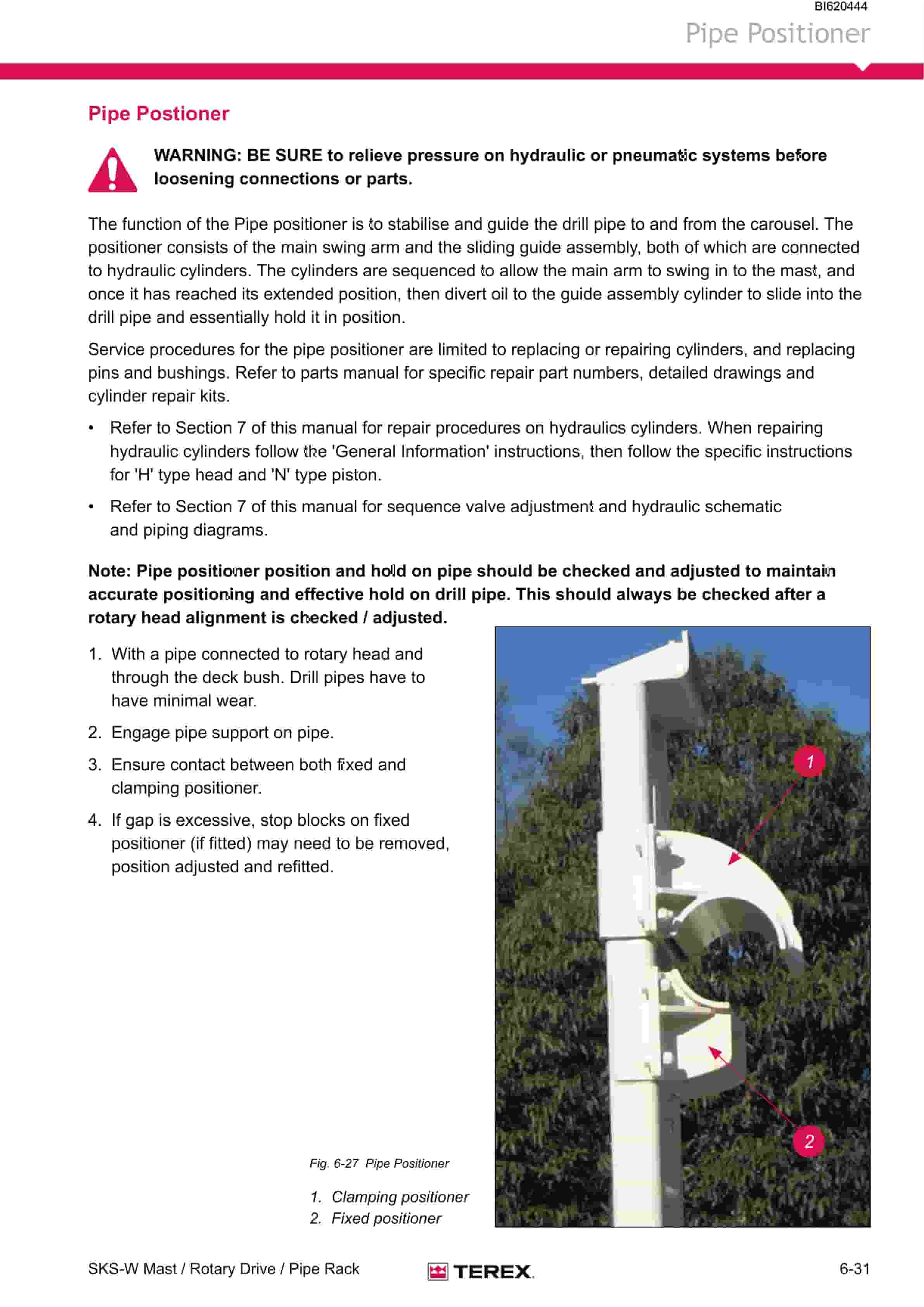
- 1.1.10.10. Pipe Positioner
- 1.1.10.10.1. Pipe Postioner
- 1.1.10.11. Carousel Pipe Rack
- 1.1.10.11.1. Major Components
- 1.1.10.11.2. Rod Handling Carousal Indexing
- 1.1.10.11.3. Pipe Rack Assembly
- 1.1.10.11.4. General Information
- 1.1.10.11.5. Pipe Rack Bearings Removal
- 1.1.10.11.6. Pipe Rack Components Inspection
- 1.1.10.11.7. Pipe Rack Assembly and Installation
- 1.1.10.11.8. Pipe Rack Roller Remove and Replace
- 1.1.10.11.9. Pipe Rack Roller Disassembly and Assembly
- 1.1.10.12. Top Sub Saver
- 1.1.10.12.1. Replacement Procedure
- 1.1.11. Section 7 Hydraulic Systems
- 1.1.11.1. Contents
- 1.1.11.1.1. Page 7-3
- 1.1.11.1.2. Page 7-4
- 1.1.11.1.3. Page 7-5
- 1.1.11.2. Hydraulic Symbols
- 1.1.11.3. Pressure Setting Sequence
- 1.1.11.3.1. Pressure Setting Sequence
- 1.1.11.3.2. Hydraulic System
- 1.1.11.4. Hydraulic Tank
- 1.1.11.4.1. Hydraulic Tank
- 1.1.11.4.2. Return Hydraulic Filters
- 1.1.11.5. Main Return and Case Drain Filter
- 1.1.11.5.1. Routine Maintenance
- 1.1.11.5.2. Changing Filter Elements
- 1.1.11.6. Main Hydraulic Pumps
- 1.1.11.6.1. Pump Identification and Parts LIst
- 1.1.11.7. Right Track / Pulldown, Left Track/Rotation Pumps
- 1.1.11.7.1. Hydraulic Piston Pumps Removal and Replacement
- 1.1.11.7.2. Main Pumps
- 1.1.11.7.3. AA4VG180 Hydraulic Pump EP2 Control
- 1.1.11.7.4. AA4VG EP Controller
- 1.1.11.7.5. EP (24V DC) Control
- 1.1.11.7.6. Technical Data
- 1.1.11.7.7. Main Hydraulic Pumps
- 1.1.11.7.8. Setting Procedure
- 1.1.11.7.9. Port Locations
- 1.1.11.7.10. Charge Pressure, High Pressure, P.O.R and Zero Position Settings
- 1.1.11.7.11. Set Charge Pressure 320psi (22 bar)
- 1.1.11.7.12. Set Crossover Relief (High Pressure) 5500psi (380bar)
- 1.1.11.7.13. Set Pressure Override (P.O.R) 5000psi (345bar)
- 1.1.11.7.14. Set Mechanical Zero Position EP Pump Control
- 1.1.11.7.15. Set Hydraulic Zero Position EP Pump Control
- 1.1.11.7.16. Removal and Inspection of Charge Pump
- 1.1.11.7.17. Removal and Installation of Shaft Seal
- 1.1.11.7.18. Routine Maintenance
- 1.1.11.7.19. Troubleshooting Procedure
- 1.1.11.8. Charge Circuit
- 1.1.11.8.1. Charge Circuit
- 1.1.11.9. Charge Filter
- 1.1.11.9.1. Routine Maintenance
- 1.1.11.9.2. Changing Filter Elements
- 1.1.11.10. Main Pumps Circuit
- 1.1.11.10.1. Main Pumps Circuit
- 1.1.11.11. Loop Filters
- 1.1.11.11.1. Routine Maintenance
- 1.1.11.11.2. Filter Assembly Loop
- 1.1.11.11.3. Changing Filter Elements
- 1.1.11.12. Rotation Circuit
- 1.1.11.12.1. Rotation Circuit
- 1.1.11.13. Rotary Drive Gearbox Motor
- 1.1.11.13.1. Rotary Drive Gearbox Motor Test and Repair
- 1.1.11.13.2. Shaft Seal Replacement
- 1.1.11.13.3. Troubleshooting
- 1.1.11.14. Tram Circuit
- 1.1.11.14.1. Tram Circuit
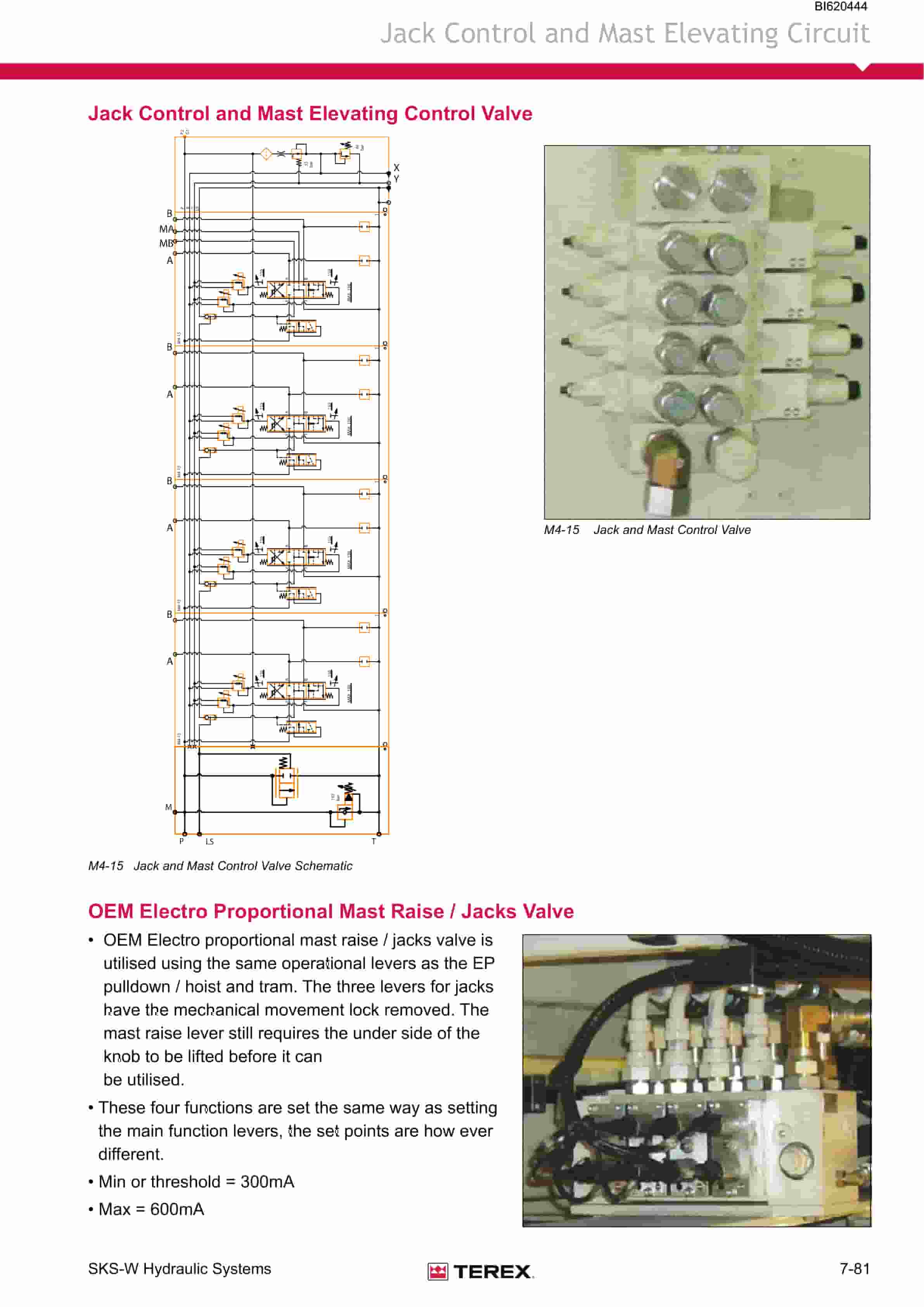
- 1.1.11.15. Main Closed Loop Circuits
- 1.1.11.15.1. Diverter Valve
- 1.1.11.15.2. Operation
- 1.1.11.15.3. Diverter Valve
- 1.1.11.16. Right Track / Pulldown and Hoist Circuit
Related products
-
Bucyrus Continuous Miner Spare Parts List 907781
$30.00 Add to cart -
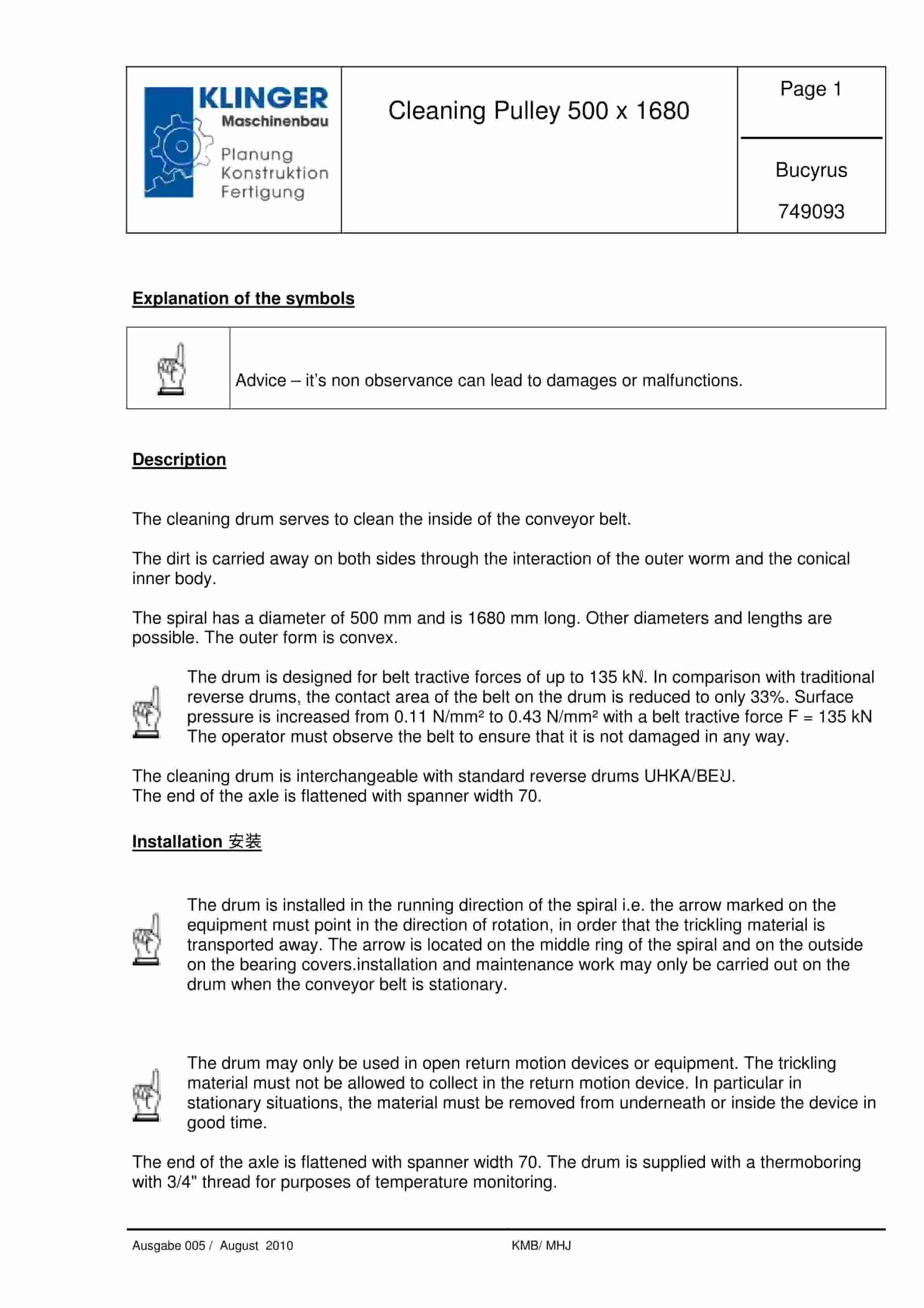
Bucyrus Cleaning Pulley 500 x 1680 Service Parts List 749093
$30.00 Add to cart -
Bucyrus Fittings, Pipes And Hoses Technical Handbook 1592605
$30.00 Add to cart -
Bucyrus Continuous Miner Spare Parts List 907793
$30.00 Add to cart -
Bucyrus Continuous Miner Spare Parts List 907782
$30.00 Add to cart


