

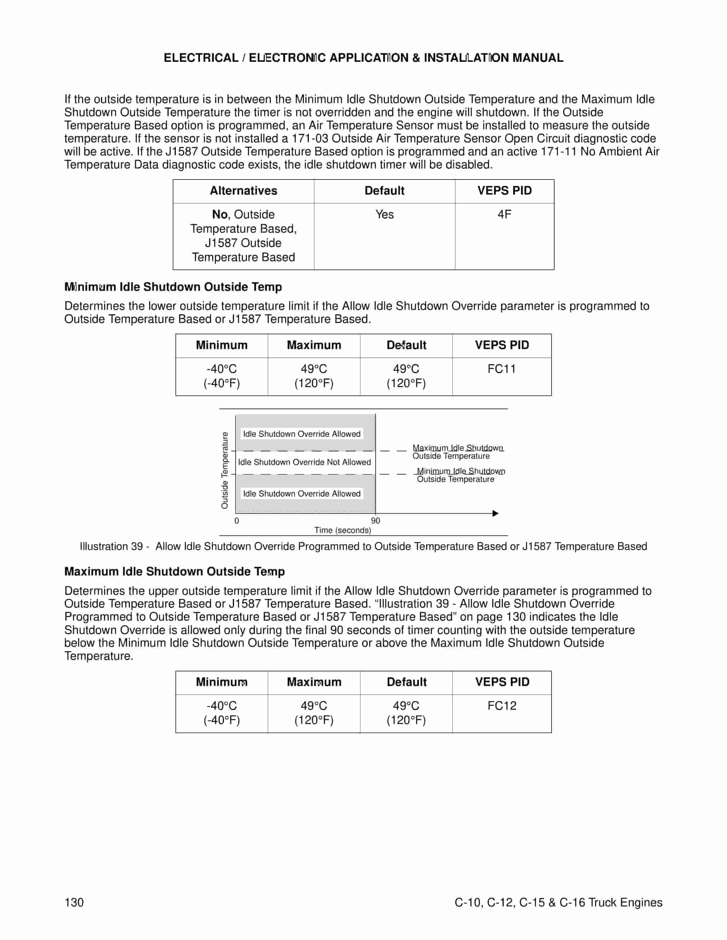
Caterpillar 2000 C-10, C-12, C-15, C-16 Truck Engines Electrical, Electronic Application, Installation Guide LEBT9010-01
$30.00
- Type Of Manual: Electrical, Electronic Application, Installation Guide
- Manual ID: LEBT9010-01
- Number of Pages: 161
- Size: 3.2MB
- Format: PDF
Product details
-
Model List:
- 2000 C-10, C-12, C-15, C-16 Truck Engines
- 1. INTRODUCTION AND PURPOSE
- 1.1. General Electronic Engine Operation
- 1.1.1. Engine Functions
- 1.1.2. Electronic Governing
- 1.1.3. Fuel/Air Ratio Control
- 1.1.4. Injection Timing Control
- 1.1.5. Torque Rise Shaping
- 1.1.6. Engine Monitoring
- 1.1.7. Code Description
- 1.1.8. C-10 and C-12 Trip Points
- 1.1.9. C-15 and C-16
- 1.1.10. Trip Point
- 1.1.11. Warning Lamp
- 1.1.12. See Figure1
- 1.1.13. See Figure1
- 1.1.14. See Figure1
- 1.1.15. See Figure1
- 1.1.16. F (91C)
- 1.1.17. F (91C)
- 1.1.18. F (109C)
- 1.1.19. F (109C)
- 1.1.20. F (103C)
- 1.1.21. F (108C)
- 1.1.22. F (107C)
- 1.1.23. F (112C)
- 1.1.24. See Figure 2
- 1.1.25. See Figure 2
- 1.1.26. See Figure 2
- 1.1.27. See Figure 2
- 1.1.28. PID- FMI
- 1.1.29. Code Description
- 1.1.30. C-10 and C-12 Trip Points
- 1.1.31. C-15 and C-16 Trip Point
- 1.1.32. Warning Lamp
- 1.1.33. See Figure1
- 1.1.34. See Figure1
- 1.1.35. See Figure1
- 1.1.36. See Figure1
- 1.1.37. mph, pwr, rpm
- 1.1.38. F (91C)
- 1.1.39. F (91C)
- 1.1.40. F (109C)
- 1.1.41. F (109C)
- 1.1.42. F (103C)
- 1.1.43. F (108C)
- 1.1.44. mph, pwr
- 1.1.45. F (106C)
- 1.1.46. F (112C)
- 1.1.47. mph, pwr
- 1.1.48. See Figure 2
- 1.1.49. See Figure 2
- 1.1.50. See Figure 2
- 1.1.51. See Figure 2
- 1.1.52. mph, pwr
- 1.1.53. PID-FMI
- 1.1.54. Code Description
- 1.1.55. Time To Shutdown
- 1.1.56. Start/Restart Time
- 1.1.57. SEC.
- 1.1.58. SEC.
- 1.2. Engine Component Overview
- 1.2.1. Figure 4 – C-15 and C-16 Left Side View
- 1.2.2. Figure 5 – C-15 and C-16 Right Side and Front View
- 1.2.3. Figure 6 – C-10 and C-12 Left Side View
- 1.2.4. Figure 7 – C-10 and C-12 Right Side and Top View
- 1.2.5. Figure 8 – C-10, C-12, C-15 and C-16 Vehicle Harness Wiring Diagram
- 1.2.6. Figure 9 – C-10, C-12, C-15 and C-16 Engine Harness Wiring Diagram
- 1.2.7. Engine Control Module (ECM)
- 1.2.8. Boost Pressure Sensor
- 1.2.9. Atmospheric Pressure Sensor
- 1.2.10. Oil Pressure Sensor
- 1.2.11. Coolant Temperature Sensor
- 1.2.12. Intake Manifold Air Temperature Sensor
- 1.2.13. Fuel Temperature Sensor
- 1.2.14. Engine Speed/Timing Sensors
- 1.3. Power and Grounding Requirements and Considerations
- 1.3.1. Grounding
- 1.3.2. Engine Connection To Vehicle Battery Ground
- 1.3.3. ECM Negative Battery Connections
- 1.3.4. Air Starter Equipped Vehicles
- 1.3.5. Sensor Common Connections
- 1.3.6. Suppression Of Voltage Transients
- 1.3.7. ECM Positive Battery Connections
- 1.4. Voltage Requirements and Considerations
- 1.4.1. Operation in 24 Volt Systems
- 1.4.2. Other Battery Connections
- 1.4.3. ECM Supplied 5V and 8V
- 1.4.4. Ignition Key Off Current
- 1.4.5. Welding on a Vehicle Equipped with a C-10, C-12, C-15 and C-16 Engine
- 1.5. Connectors and Wiring Harness Requirements
- 1.5.1. ECM Connector
- 1.5.2. ECM Connector Wire Gauge Size
- 1.5.3. ECM Connector Wire Insulation and Gauge Size
- 1.5.4. Required ECM 70 Terminal Connector Parts
- 1.5.5. AMP 776093-1 Stamped Formed Socket with 16 and 18 AWG SXL Wire or with 14, 16 or 18 AWG G…
- 1.5.6. Deutsch 0462-209-1631 Solid Socket with 14 AWG Wire (Caterpillar P/N 126-1768)
- 1.5.7. Deutsch 0462-201-1631 Solid Socket with 16 and 18 AWG Wire (Caterpillar P/N 9X3402)
- 1.5.8. Required Deutsch Parts
- 1.6. Accelerator Pedal Position Sensors
- 1.6.1. Figure 22 – 176-1602 or 176-1604 Accelerator Pedal Position Sensor with Deutsch DT Connector
- 1.6.2. Figure 23 – 176-1605 Accelerator Pedal Position Sensor with Packard Connector
- 1.6.3. Accelerator Pedal Position Sensor Electrical Specifications
- 1.6.4. ECM Supplied 8V
- 1.6.5. Mounting the Accelerator Position Sensor
- 1.6.6. Remote Accelerator Position Sensor PWM Input, Input 8
- 1.7. Vehicle Speed Circuit
- 1.7.1. General Vehicle Speed Source Requirements
- 1.7.2. Passive Magnetic Vehicle Speed Sensor Electrical Requirements
- 1.7.3. Passive Magnetic Vehicle Speed Circuit Options
- 1.7.4. Vehicle Speed Connections To Automatic Transmissions with Electronic Vehicle Speed Source
- 1.8. ECM Speedometer and Tachometer Outputs
- 1.8.1. Speedometer And Tachometer
- 1.8.2. Speedometer And Tachometer Output Electrical Specifications and Connections
- 1.8.3. Connection Of Devices Other Than A Speedometer/Tachometer
- 1.8.4. Speedometer and Tachometer Output Accuracy
- 1.9. Lamp Outputs
- 1.9.1. Electrical Specifications
- 1.9.2. Check Engine Lamp Operation
- 1.9.3. Warning Lamp Operation
- 1.9.4. Output 1
- 1.9.5. Output 9
- 1.10. Engine Monitoring and OEM Requirements
- 1.10.1. OEM provided and installed components required
- 1.10.2. Customer Parameter programming required
- 1.11. Coolant Level Sensor
- 1.11.1. Coolant Level Sensor Environmental Compatibility
- 1.11.2. Coolant Level Sensor Mounting Guidelines
- 1.11.3. Four Pin Coolant Level Sensor Electrical Specifications
- 1.12. Idle Shutdown and Ambient Air Temperature Sensor Installation
- 1.12.1. Idle Shutdown Timer
- 1.12.2. Ambient Air Temperature Sensor
- 1.13. OEM Installed Switch Inputs
- 1.13.1. Switch to Ground Electrical Specifications
- 1.13.2. Sensor Common Connections
- 1.13.3. Preset Switch to Ground Inputs
- 1.13.4. Cruise Control
- 1.13.5. Factory Preset Cruise Control Switches Operation
- 1.13.6. Additional Switch to Ground Inputs
- 1.13.7. Diagnostic Enable
- 1.13.8. Two-Speed Axle On/Off Switch
- 1.13.9. Switch-to-Battery Electrical Specifications
- 1.13.10. Ignition Key Switch to Positive Battery
- 1.13.11. Programmable Switch to Positive Battery Inputs
- 1.13.12. Service Brake Pedal Position Switch 2 Function
- 1.13.13. Transmission Neutral Switch
- 1.14. PTO Engine Governor and Idle Speed Control
- 1.14.1. OEM provided and installed components required
- 1.14.2. Customer Parameter programming required
- 1.14.3. Dedicated PTO Operation
- 1.14.4. Advantages of PTO Configurations
- 1.14.5. Inputs
- 1.14.6. Sensor Common for PTO Applications
- 1.14.7. PTO On/Off Switch Operation
- 1.14.8. PTO Switch On Lamps
- 1.14.9. PTO Interlocks
- 1.14.10. PTO Customer Access Connector
- 1.14.11. PTO Configurations
- 1.14.12. PTO Configuration – Cab Switches
- 1.14.13. Parameter settings for PTO Configuration Cab Switches with One Speed Above Idle Circuit
- 1.14.14. Parameter settings for PTO Configuration Cab Switches with One Speed Above Idle Circuit
- 1.14.15. Parameter settings for PTO Configuration Remote Switches with One Speed Above Idle Circuit
- 1.14.16. Parameter settings for PTO Configuration Remote Switches with One Speed Above Idle Circuit
- 1.14.17. Parameter settings for PTO Configuration Remote Throttle with One Speed Above Idle Circuit
- 1.14.18. Parameter settings for PTO Configuration Remote Throttle with Set/Resume
- 1.14.19. Parameter settings for PTO Configuration Cab Switches with One Speed Above Idle Circuit
- 1.15. Engine Retarder
- 1.15.1. Engine Retarder Control
- 1.15.2. Engine Retarder Solenoid Selector Switch
- 1.15.3. Retarder Solenoid Operation
- 1.15.4. Engine rpm is above 800 rpm
- 1.15.5. Accelerator Pedal Position< 7
- 1.15.6. Clutch pedal released
- 1.16. Programmable Outputs
- 1.16.1. Output 2, Output 3, and Output 4 Electrical Specifications
- 1.16.2. Engine Running Output
- 1.16.3. Engine Shutdown Output
- 1.16.4. Starting Aid Output
- 1.16.5. A Starting Aid Output parameter is available to connect to a relay and/or solenoid to control a C…
- 1.16.6. Typical Starting Aid Systems inject ether into the intake manifold to aid engine starting during …
- 1.16.7. The Intake Manifold Air Temperature reading is used to determine if conditions require use of the…
- 1.17. Cooling Fan
- 1.17.1. Output 5 Electrical Specifications
- 1.17.2. Cooling Fan Output Operation with Fan Control Type Programmed to On-Off
- 1.17.3. The ECM will turn the cooling fan ON under any of the following conditions if engine rpm is less …
- 1.17.4. Conditions to turn Fan ON for C-15 and C-16
- 1.17.5. Conditions to turn Fan ON for C-10 and C-12
- 1.17.6. Engine Not Running
- 1.17.7. Engine Not Running
- 1.17.8. During Engine Cranking
- 1.17.9. During Engine Cranking
- 1.17.10. Coolant Sensor Temperature > 216F (102C)
- 1.17.11. Coolant Sensor Temperature > 205F (96C)
- 1.17.12. Active Coolant Temperature Sensor Diagnostic
- 1.17.13. Active Coolant Temperature Sensor Diagnostic
- 1.17.14. Intake Manifold Air Temperature > 189F (87C)
- 1.17.15. Intake Manifold Air Temperature > 189F (87C)
- 1.17.16. Intake Manifold Air Temperature > 162F (72C) with Boost Pressure > 10 psi (70 kPa)
- 1.17.17. Intake Manifold Air Temperature > 162F (72C) with Boost Pressure > 10 psi (70 kPa)
- 1.17.18. Engine Retarder ON in high mode > 2 seconds, when Fan With Engine Retarder in High Mode is progr…
- 1.17.19. Engine Retarder ON in high mode > 2 seconds, when Fan With Engine Retarder in High Mode is progr…
- 1.17.20. A/C High Pressure Switch Input is Open or ECM is Counting
- 1.17.21. A/C High Pressure Switch Input is Open or ECM is Counting
- 1.17.22. PTO On/Off Switch in ON position, when PTO Activates Cooling Fan parameter is programmed to Cont…
- 1.17.23. PTO On/Off Switch in ON position, when PTO Activates Cooling Fan parameter is programmed to Cont…
- 1.17.24. Manual Fan Override Switch is ON, when the Fan Override Switch parameter is programmed to a sele…
- 1.17.25. Manual Fan Override Switch is ON, when the Fan Override Switch parameter is programmed to a sele…
- 1.17.26. These items are dependent upon programming of Customer Parameters.
- 1.17.27. NOTE The ECM will turn the cooling fan OFF for 10 seconds during an engine shutdown.
- 1.17.28. The fan will remain on for a minimum of 30 seconds following ECM initiated activation except foll…
- 1.17.29. Conditions to turn Fan OFF for C-15 and C-16
- 1.17.30. Conditions to turn Fan OFF for C-10 and C-12
- 1.17.31. Coolant Sensor Temperature < 208F (98C)
- 1.17.32. Coolant Sensor Temperature < 198F (92C)
- 1.17.33. The fan has been ON for at least 30 seconds
- 1.17.34. The fan has been ON for at least 30 seconds
- 1.17.35. Intake Manifold Air Temperature < 151F (66C)
- 1.17.36. Intake Manifold Air Temperature < 151F (66C)
- 1.17.37. Engine Retarder ON Strategy is not Active
- 1.17.38. Engine Retarder ON Strategy is not Active
- 1.17.39. A/C High Pressure Switch not Active
- 1.17.40. A/C High Pressure Switch not Active
- 1.17.41. PTO On/Off Switch in OFF position
- 1.17.42. PTO On/Off Switch in OFF position
- 1.17.43. Manual Fan Override Switch in OFF position
- 1.17.44. Manual Fan Override Switch in OFF position
- 1.17.45. Key Switch turned OFF with Engine Speed Present
- 1.17.46. Key Switch turned OFF with Engine Speed Present
- 1.17.47. NOTE The ECM will turn the cooling fan OFF for 10 seconds during an engine shutdown.
- 1.17.48. Direct Mode Operation for C-15 and C-16
- 1.17.49. Direct Mode Operation for C-10 and C-12
- 1.17.50. Engine Not Running.
- 1.17.51. Engine Not Running.
- 1.17.52. During Engine Cranking.
- 1.17.53. During Engine Cranking.
- 1.17.54. Coolant Sensor Temperature increasing > 217F (103C).
- 1.17.55. NOTE If the cooling fan is operating in Direct Mode the fan will continue to operate in Direct M…
- 1.17.56. Coolant Sensor Temperature increasing > 203F (95C). NOTE If the cooling fan is operating in Di…
- 1.17.57. Active Coolant Temperature Sensor Diagnostic.
- 1.17.58. Active Coolant Temperature Sensor Diagnostic.
- 1.17.59. Intake Manifold Air Temperature increasing > 178F (81C).
- 1.17.60. NOTE If the cooling fan is operating in Direct Mode the fan will continue to operate in Direct M…
- 1.17.61. Intake Manifold Air Temperature increasing > 178F (81C).
- 1.17.62. NOTE If the cooling fan is operating in Direct Mode the fan will continue to operate in Direct M…
- 1.17.63. Intake Manifold Air Temperature increasing > 149F (65C) if Boost Pressure > 70 kPa (10 psi). NO…
- 1.17.64. Intake Manifold Air Temperature increasing > 149F (65C) if Boost Pressure > 70 kPa (10 psi).
- 1.17.65. NOTE If the cooling fan is operating in Direct Mode the fan will continue to operate in Direct M…
- 1.17.66. Engine Retarder ON in high mode > 3 seconds, when Fan With Engine Retarder in High Mode is progr…
- 1.17.67. Engine Retarder ON in high mode > 3 seconds, when Fan With Engine Retarder in High Mode is progr…
- 1.17.68. PTO On/Off Switch in ON position, when PTO Activates Cooling Fan parameter is programmed to Cont…
- 1.17.69. PTO On/Off Switch in ON position, when PTO Activates Cooling Fan parameter is programmed to Cont…
- 1.17.70. Manual Fan Override Switch is ON, when the Fan Override Switch parameter is programmed to a sele…
- 1.17.71. Manual Fan Override Switch is ON, when the Fan Override Switch parameter is programmed to a sele…
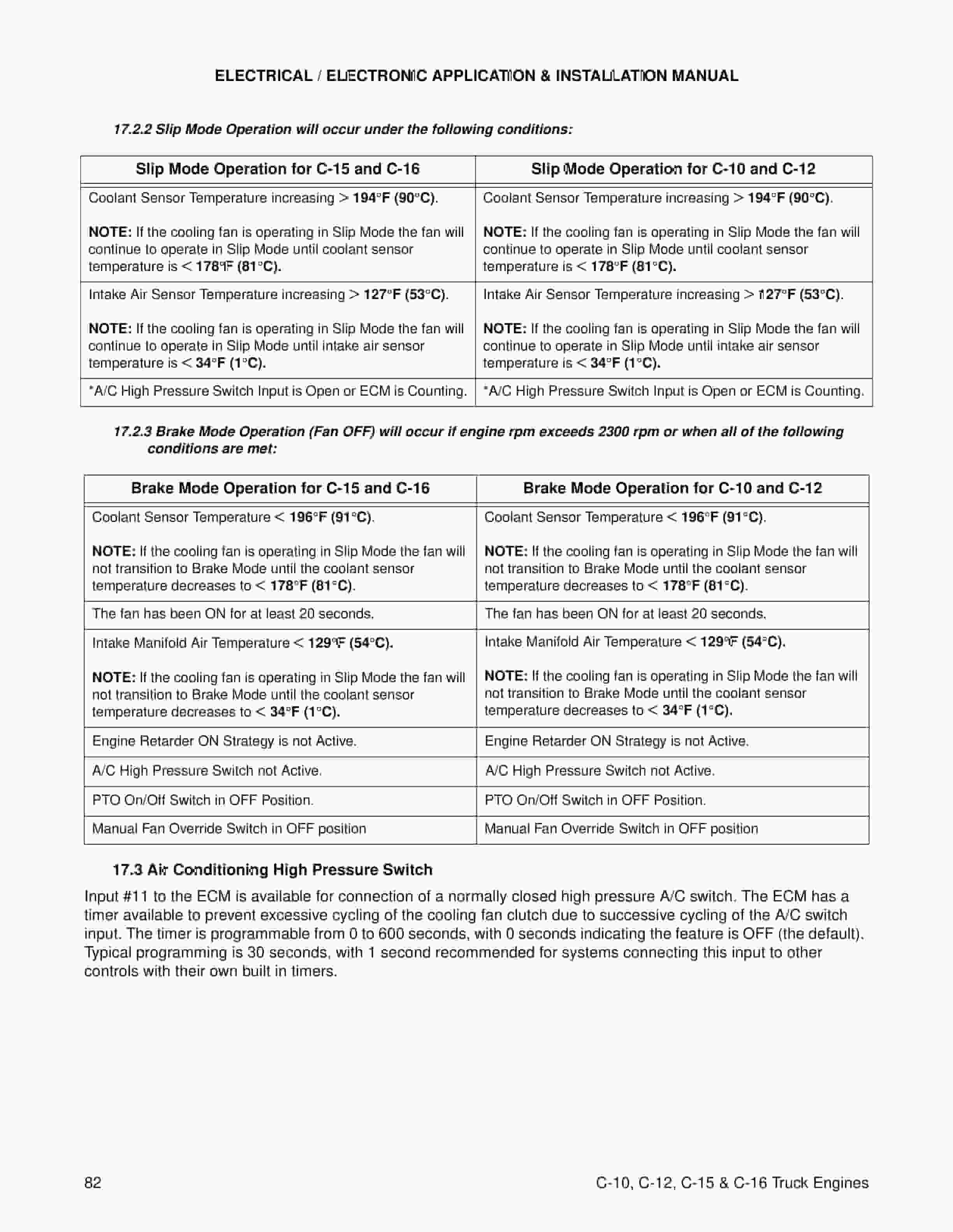
- 1.17.72. Slip Mode Operation for C-15 and C-16
- 1.17.73. Slip Mode Operation for C-10 and C-12
- 1.17.74. Coolant Sensor Temperature increasing > 194F (90C).
- 1.17.75. NOTE If the cooling fan is operating in Slip Mode the fan will continue to operate in Slip Mode …
- 1.17.76. Coolant Sensor Temperature increasing > 194F (90C). NOTE If the cooling fan is operating in Sl…
- 1.17.77. Intake Air Sensor Temperature increasing > 127F (53C).
- 1.17.78. NOTE If the cooling fan is operating in Slip Mode the fan will continue to operate in Slip Mode …
- 1.17.79. Intake Air Sensor Temperature increasing > 127F (53C). NOTE If the cooling fan is operating in…
Related products
-
Caterpillar F40DSA, F50DSA, F60DSA, M40DSA, M50DSA, MC60DSA Lift Trucks MicroCommand Control System Schematic SENB8335
$30.00 Add to cart -
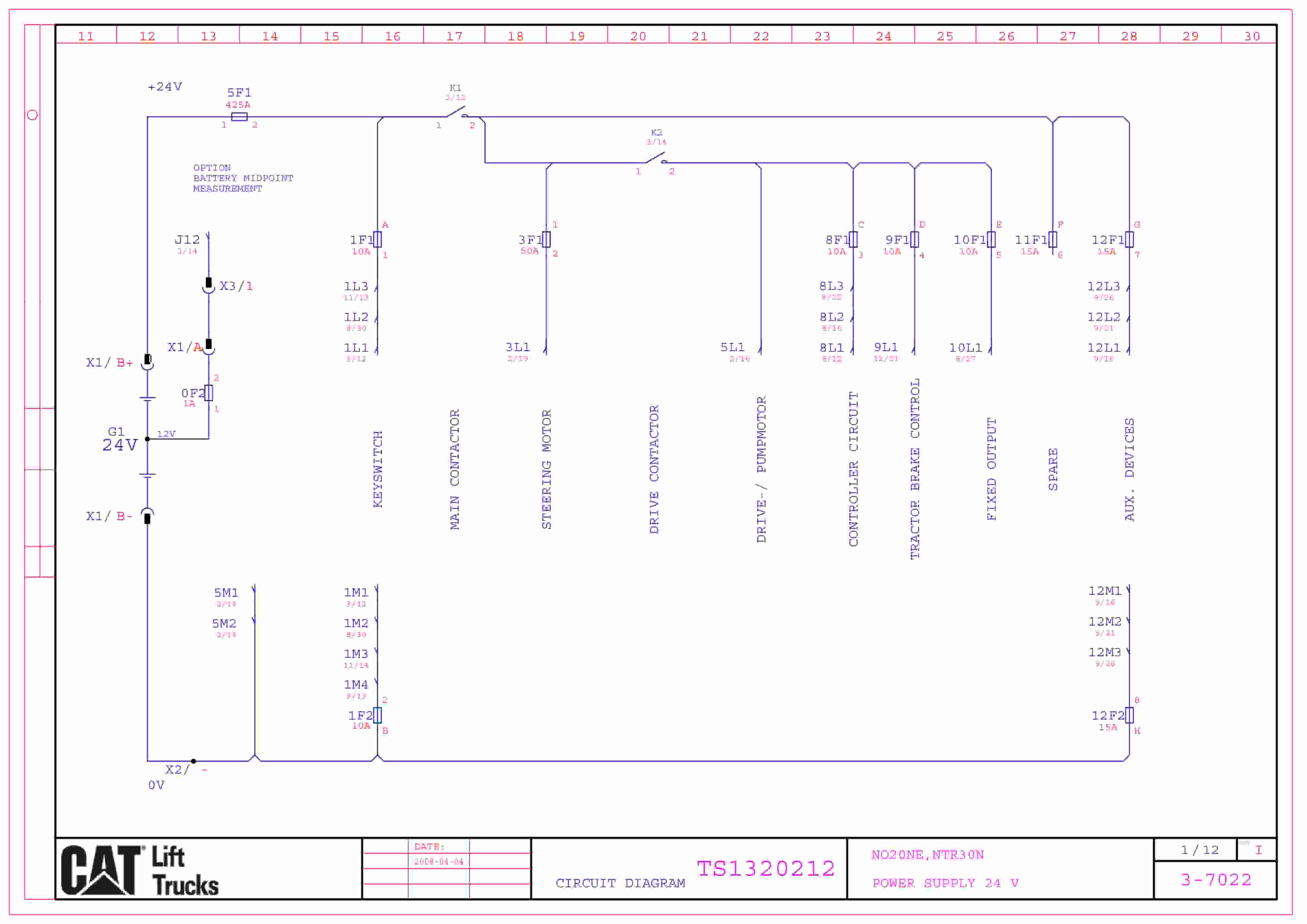
Caterpillar NO20NE, NTR30N Electrical Diagrams TS1320212
$30.00 Add to cart -
Caterpillar F25 to FC40 Lift Trucks Hydraulic System Schematic SENB8512
$30.00 Add to cart -
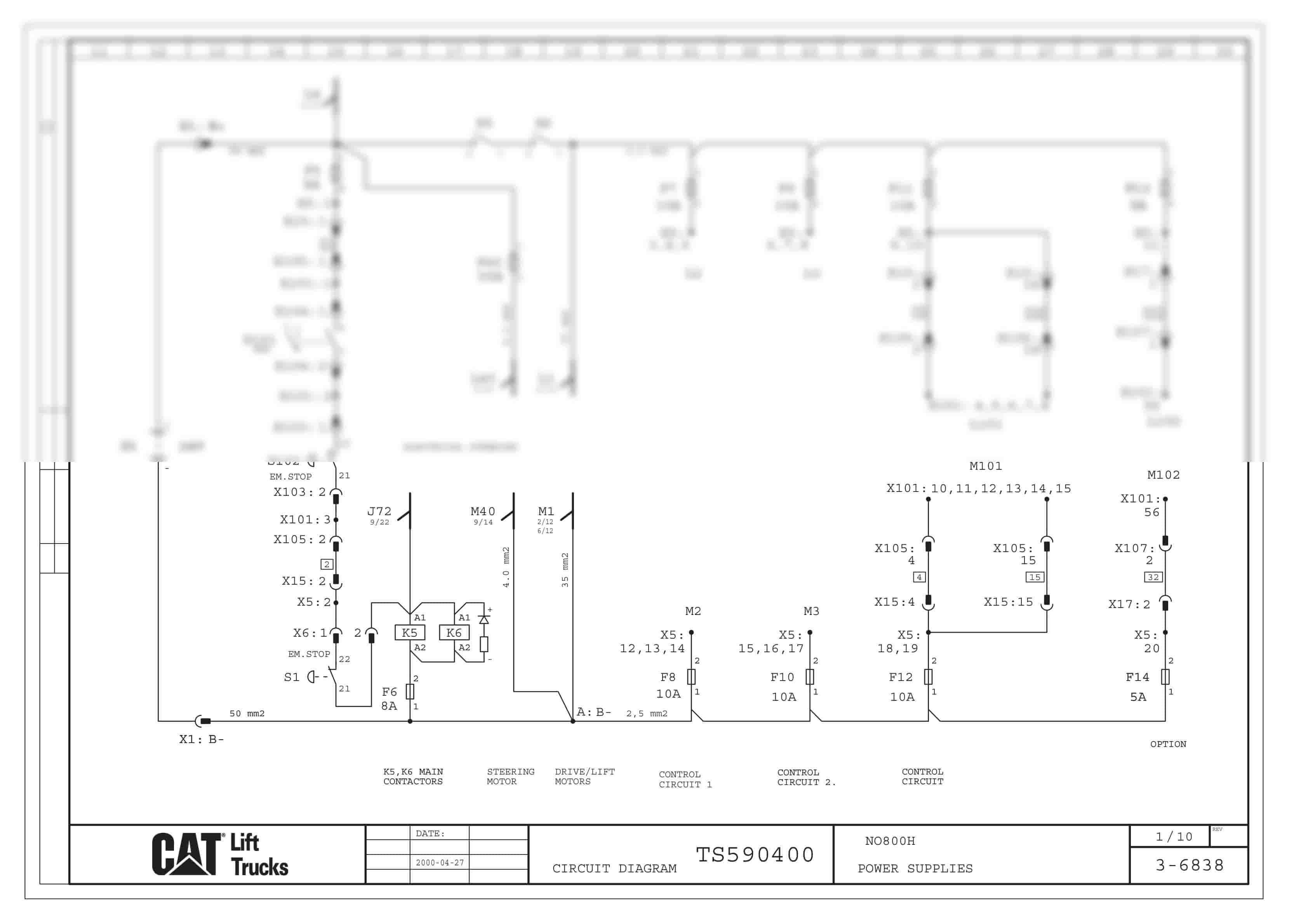
Caterpillar NO800H Electrical Diagrams TS590400
$30.00 Add to cart -
Caterpillar M25D to M50D Lift Trucks MicroCommand Control System Schematic SENB8456
$30.00 Add to cart


