

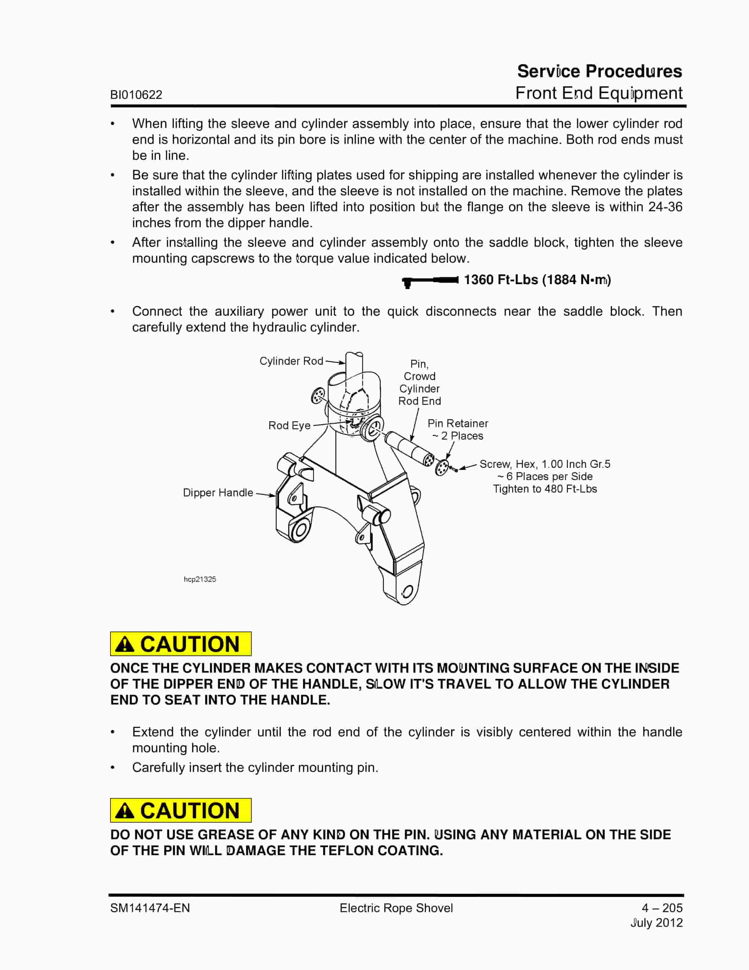
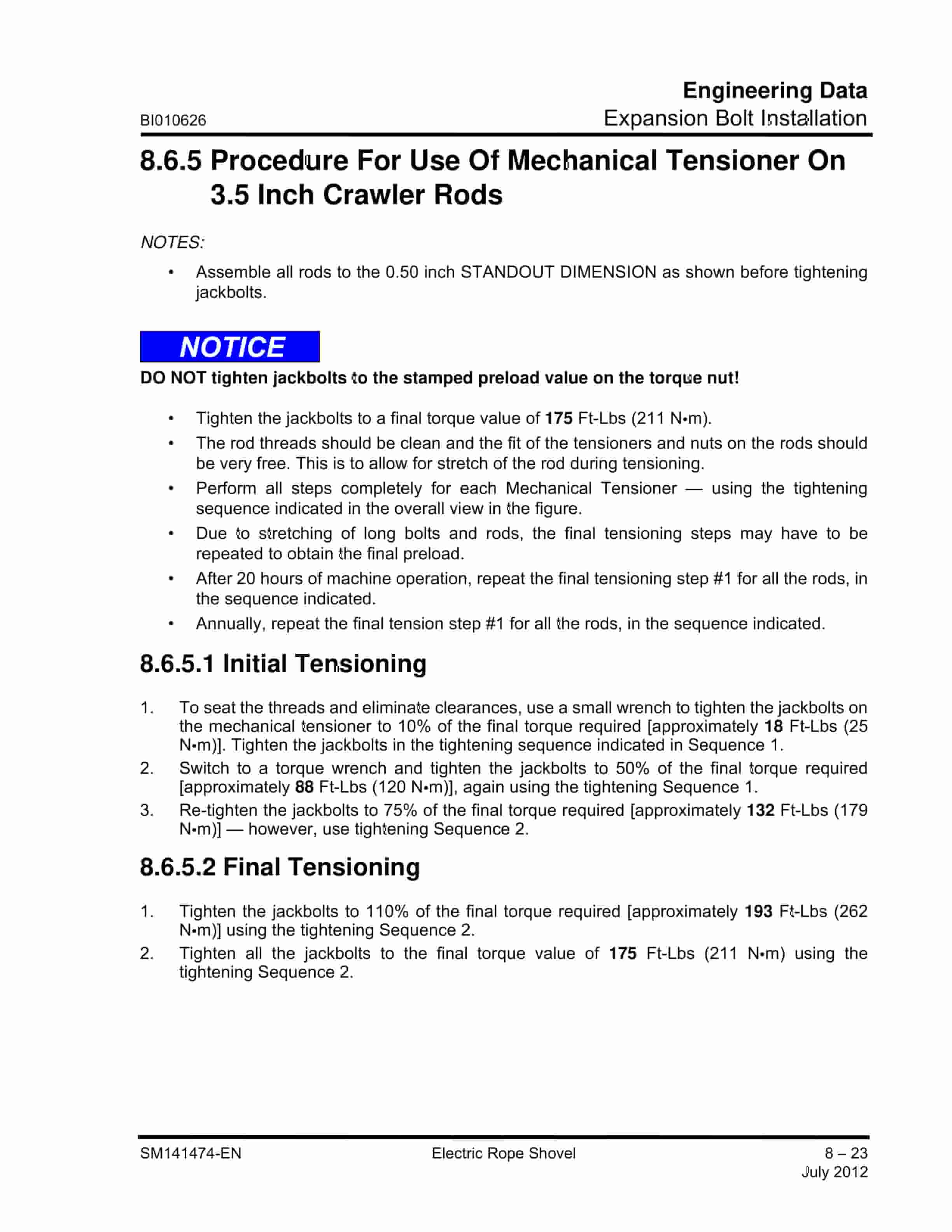
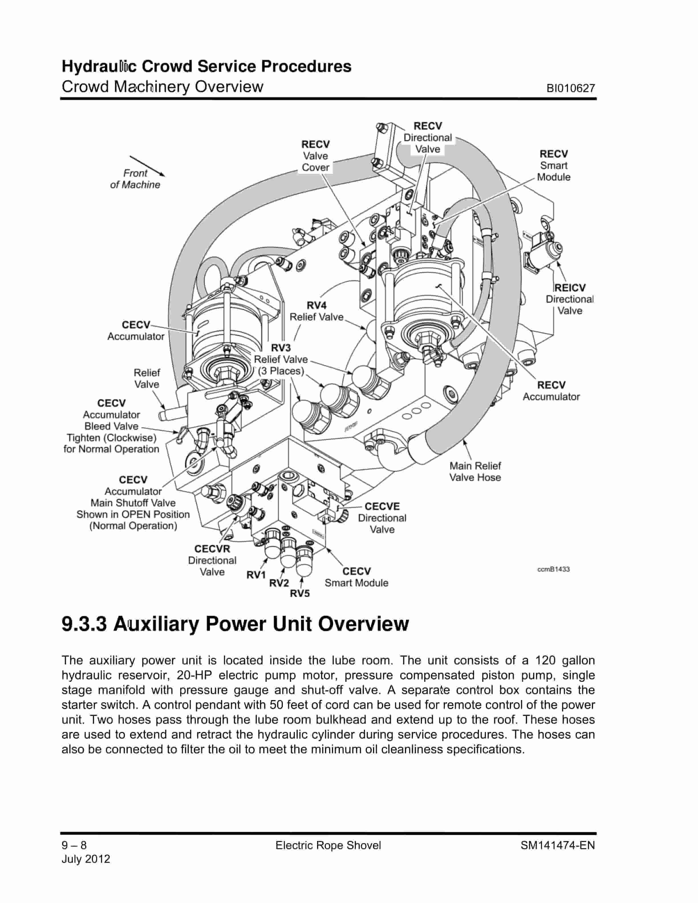
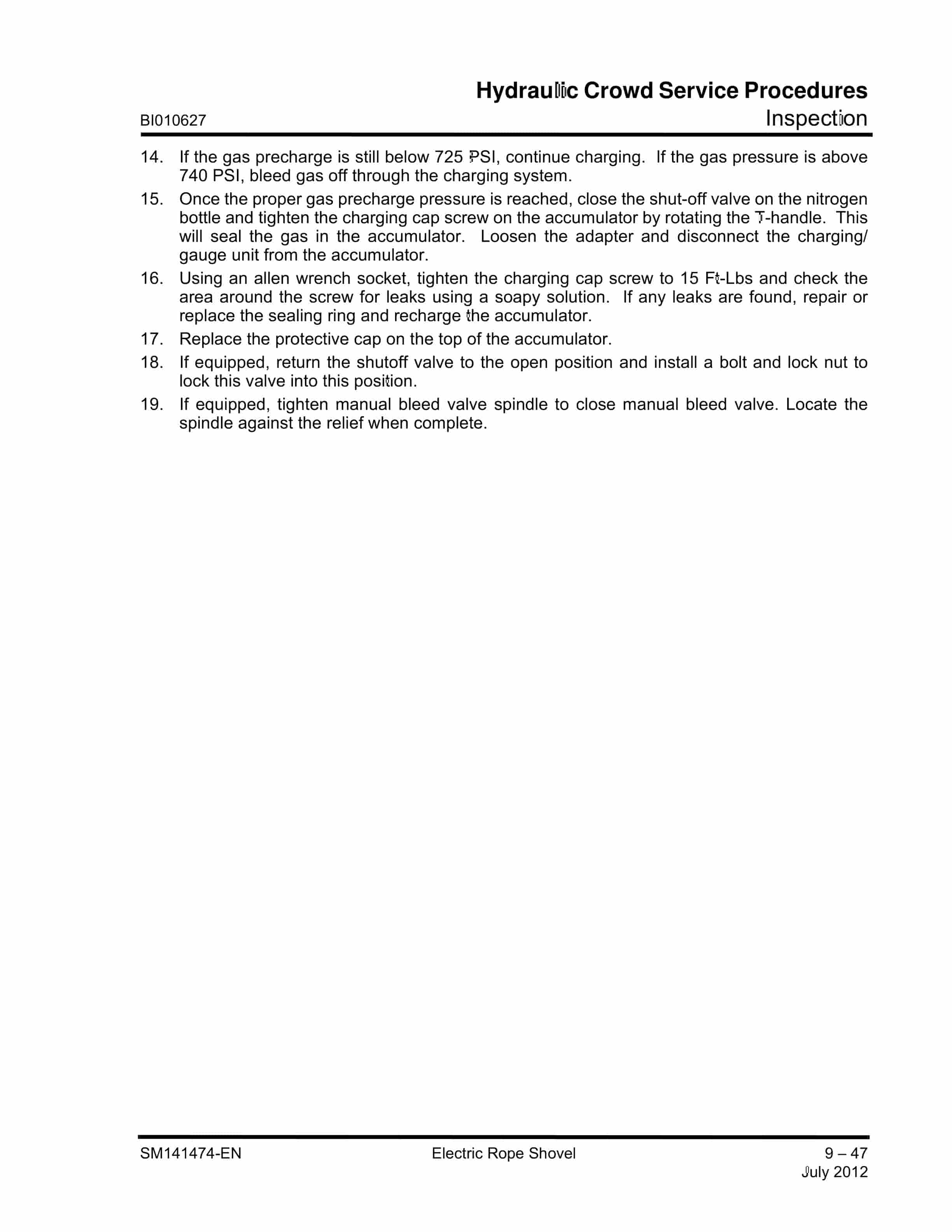
Caterpillar 7495 Electric Rope Shovel Service Manual BI010616
$30.00
- Type Of Manual: Service Manual
- Manual ID: BI010616
- Number of Pages: 782
- Size: 72.6MB
- Format: PDF
Product details
-
Model List:
- 7495 Electric Rope Shovel
- 1. BI010591-EN.pdf
- 1.1. SM – EN
- 1.2. OM – EN
- 1.3. ESM – EN Page 1
- 1.4. ESM – EN Page 2
- 1.5. VM – EN Page 1
- 1.6. VM – EN Page 2
- 2. SM141474-EN-Safety.pdf
- 2.1. Safety Symbols
- 2.2. Safety Precautions
- 2.2.1. General Precautions
- 2.2.2. Maintenance Precautions
- 2.2.3. Operating Precautions
- 2.2.4. Fire Prevention
- 2.2.5. Common Safety Features
- 2.3. Warning Signs And Decals
- 3. SM141474-EN-Introduction.pdf
- 3.1. About This Manual
- 3.1.1. Purpose
- 3.1.2. Organization
- 3.1.3. Terminology
- 3.1.4. Revisions
- 3.1.5. Precautions and Disclaimers
- 3.1.6. Contact
- 3.2. Swinging Restraint Ballast Box Support
- 3.2.1. Ballast Box Support
- 3.2.2. Swinging Restraint
- 3.3. Machine Overview
- 3.4. Lower Works
- 3.4.1. Crawlers
- 3.4.2. Truck Frame
- 3.4.3. Swing Rack
- 3.4.4. Roller Circle
- 3.4.5. Propel Machinery
- 3.4.6. Collector Rings
- 3.4.7. Stinger (Trail Cable Support)
- 3.5. Rotating Deck
- 3.5.1. Revolving Frame
- 3.5.2. Center Pintle
- 3.5.3. Deck Extensions
- 3.5.4. Ballast Box
- 3.5.5. Machinery House
- 3.5.6. A-Frame
- 3.5.7. Hoist Machinery
- 3.5.8. Swing Machinery
- 3.5.9. Crowd Machinery Overview
- 3.5.10. Operators Cab
- 3.5.11. Compressed Air System
- 3.5.12. Automatic Lubrication System
- 3.5.13. Lube Reservoir Fill / Overflow Plumbing
- 3.6. Front End Equipment
- 3.6.1. Suspension Strands
- 3.6.2. Boom
- 3.6.3. Running Ropes
- 3.6.4. Saddle Block
- 3.6.5. Dipper Handle – Hydraulic Crowd
- 3.6.6. Dipper
- 3.6.7. LatchFreeTM Dipper Assembly
- 3.6.8. Padlocks
- 3.6.9. Dipper Trip
- 3.7. Machine Specifications with HydraCrowd Typical
- 3.8. General Estimated Component Weights
- 3.8.1. Lower Works
- 3.8.2. Upper Works
- 3.8.3. Front End
- 4. SM141474-EN-Lubrication.pdf
- 4.1. Lubrication Principles
- 4.2. Greasing Main A.C. Drive Motors
- 4.2.1. Type of Grease
- 4.2.2. Initial Commissioning
- 4.2.3. Maintenance
- 4.2.4. Regreasing Intervals
- 4.3. Lubricant Selection
- 4.4. Oil Fill Capacities
- 4.4.1. Types Of Lubricants And Capacities
- 4.5. Gearcase Lubricant Replacement/Sampling
- 4.5.1. Lubricant Change Cycle
- 4.6. Automatic Lubrication System
- 4.6.1. Lube Room
- 4.6.2. Lube Reservoir Fill / Overflow Plumbing
- 4.6.3. Auto Lube Control Panel
- 4.6.4. Lower Works Lubrication
- 4.6.5. Revolving Frame Lubrication
- 4.6.6. Hoist Rope Rollers Lubrication
- 4.6.7. Front End Lubrication
- 4.6.8. Lubricant Injectors
- 4.7. Propel Machinery Lubrication
- 4.8. Hoist Machinery Lubrication
- 4.8.1. Hoist OGL Reservoir
- 4.8.2. Hoist Oil Cooler
- 4.8.3. Filter Element Cleaning
- 4.9. Swing Machinery Lubrication
- 4.10. Hydraulic Crowd Machinery Lubrication
- 4.10.1. Pump Drive Transmission (PDT)
- 4.10.2. Oil Pump
- 4.11. Hydraulic Cleanliness
- 4.11.1. Contamination Control
- 4.11.2. Filters
- 4.11.3. Moisture Removal
- 4.12. Air Compressor Lubrication
- 4.12.1. ACSL – Air Compressor (Screw-Type) Lubricant
- 5. AM11093-EN.pdf
- 5.1. AM11093 ERS Manual Disclaimer Page_EN.pdf
- 5.1.1. SM – EN
- 5.2. ERS Manual Back Cover.pdf
- 5.2.1. English
- 5.2.2. BlankPage.pdf
- 6. SM141474-EN-PreventiveMaintenance.pdf
- 6.1. Introduction
- 6.1.1. Preventive Maintenance Program
- 6.1.2. Elements of an Effective Maintenance Program
- 6.1.3. Scheduled Preventive Maintenance Program
- 6.1.4. General Safety Considerations
- 6.2. Maintenance During Machine Operation
- 6.2.1. Maintenance Precautions
- 6.3. Preventive Maintenance for Lubrication
- 6.3.1. Lubricant Cleanliness
- 6.4. Frequency of Inspection and Maintenance
- 6.5. Maintenance Schedules
- 6.5.1. Maintenance Inspection Check Points
- 6.6. Hydraulic Crowd Service Schedule
- 6.7. HydraCrowd Health Monitoring Checks
- 6.8. Major Component Locations
- 7. SM141474-EN-ServiceProcedures.pdf
- 7.1. Lower Works
- 7.1.1. Truck Frame Assembly
- 7.1.2. Swing Rack Assembly
- 7.1.3. Roller Circle Assembly
- 7.1.4. Crawler Belts
- 7.1.5. Crawler Side Frame Assembly
- 7.1.6. Crawler Front Idler Roller Assembly
- 7.1.7. Propel Shaft Assembly
- 7.1.8. Propel Machinery
- 7.2. Rotating Deck
- 7.2.1. Revolving Frame
- 7.2.2. Center Pintle
- 7.2.3. Collector Rings
- 7.2.4. Stinger (Trail Cable Support)
- 7.2.5. Swing Machinery
- 7.2.6. Hoist Machinery
- 7.2.7. Hoist Oil Cooler
- 7.2.8. Crowd Machinery Overview
- 7.2.9. Operators Cab Mounting
- 7.2.10. Operators Seat Replacement
- 7.2.11. Joystick Replacement
- 7.2.12. Wiper Arm Replacement
- 7.2.13. Wiper Blade Replacement
- 7.2.14. Wiper Motor Replacement
- 7.3. Machinery House
- 7.3.1. Walkways, Stairways, and Handrails
- 7.4. Front End Equipment
- 7.4.1. Boom Assembly
- 7.4.2. Boom Limit Switch Installation
- 7.4.3. Boom Point Sheaves
- 7.4.4. Boom Bumper
- 7.4.5. Saddle Block
- 7.4.6. Dipper Handle – Hydraulic Crowd
- 7.4.7. LatchFreeTM Dipper Assembly
- 7.4.8. Dipper Removal Installation
- 7.4.9. Dipper Trip Assembly
- 7.4.10. A-Frame
- 7.4.11. Auxiliary Winch
- 7.4.12. Hoist Rope Support Roller
- 7.4.13. Boom Support Ropes
- 7.4.14. Wire Ropes
- 7.4.15. Hoist Rope Reeving Replacement
- 7.4.16. Dipper Trip Rope Reeving Replacement
- 7.4.17. Hoist and Crowd Limit Systems
- 8. SM141474-EN-BrakesAndCouplings.pdf
- 8.1. Brakes
- 8.1.1. Disc Brake Operation
- 8.1.2. Maintenance
- 8.1.3. Brake Adjustment Specifications
- 8.1.4. Hoist Brake
- 8.1.5. Propel Brake
- 8.1.6. Swing Brake
- 8.1.7. Spring Replacement All Brakes
- 8.1.8. Friction Disc Replacement All Brakes
- 8.1.9. O-Ring Replacement All Brakes
- 8.1.10. Brake Wear Release Switches Single Disc Brakes
- 8.1.11. Brake Wear Release Switches Multiple Disc Brakes
- 8.2. Couplings
- 8.2.1. Grid Couplings
- 8.2.2. Gear Couplings
- 9. SM141474-EN-CompressedAirSystem.pdf
- 9.1. Air Compressor
- 9.2. Air Dryer Assembly
- 9.3. Lockout Valves
- 9.4. Safety Warnings
- 10. SM141474-EN-AirFiltration.pdf
- 10.1. House Filter Fans
- 10.1.1. Lubrication
- 10.1.2. Dynavane Air Cleaner
- 10.2. Air Conditioner/Heater
- 10.2.1. Evaporator
- 10.2.2. Condenser
- 10.2.3. Pressurizer
- 10.2.4. Specifications
- 11. SM141474-EN-EngineeringData.pdf
- 11.1. Capscrew (Bolt) Grade
- 11.1.1. Bolt Tightening
- 11.2. Measurement Systems
- 11.2.1. Linear Measurements
- 11.2.2. Area Measurements
- 11.2.3. Volume Measurements
- 11.2.4. Torque Measurements
- 11.2.5. Weight Measurements – Conventional
- 11.3. Wire Locking Capscrews
- 11.4. Torque Nut Installation
- 11.5. Expansion Bolt Installation
- 11.5.1. Tightening Procedure for 1.25-Inch Torque Nut
- 11.5.2. Tightening Procedure for 2-Inch Torque Nut
- 11.5.3. Tightening Procedure for 2-Inch Torque Nut
- 11.5.4. Tightening Procedure for 3.5-Inch Torque Nut
- 11.5.5. Procedure For Use Of Mechanical Tensioner On 3.5 Inch Crawler Rods
- 11.5.6. Tightening Procedures – Expansion Bolts
- 11.6. Torque Nut Removal Procedure
- 11.6.1. Thread Lubrication
- 11.7. Torque Nut Helpful Hints
- 11.8. Locking Assemblies
- 11.8.1. Locking Assembly Removal
- 11.9. Pinion and Hub Installation
- 11.9.1. Removal from a Shaft
- 11.9.2. Mounting a Pinion or Hub on a Shaft
- 11.9.3. Pre-heat Advance Requirements – Pinions and Hubs
- 11.9.4. Motor Coupling Pre-Heat Advance Requirements
- 11.10. Open Gear Contact Check
- 11.11. Open Gear Break-In
- 11.12. Maintenance Welding
- 11.12.1. Welding Electrodes
- 11.12.2. Repair Welding of Cracks
- 11.12.3. Repair Welding of Broken Parts
- 11.12.4. Repair Welding Swing Rack Teeth
- 11.12.5. Welding and Cutting Equipment
- 11.12.6. Stress Relieving Temperature Measuring Equipment
- 11.13. Wire Rope Care and Maintenance
- 11.13.1. Storage
- 11.13.2. Checking Diameter
- 11.13.3. Handling Wire Rope
- 11.13.4. Seizing Wire Rope
- 11.13.5. End Preparations/Terminations
- 11.13.6. Wire Rope Clips
- 11.13.7. Inspection of Sheaves and Drums
- 11.13.8. Breaking In a New Wire Rope
- 11.13.9. Inspection Data
- 11.13.10. Guideline to Inspections and Reports
- 11.14. Seals
- 11.14.1. Seal Installation
- 11.14.2. Gearcase Sealing
- 12. SM141474-EN-HydraCrowdServiceProcedures.pdf
- 12.1. Hydraulic System Cleanliness
- 12.2. Hydraulic System Oil Contamination Guide
- 12.3. Crowd Machinery Overview
- 12.3.1. Hydraulic Crowd Cylinder Overview
- 12.3.2. Cylinder Control Manifold Overview
- 12.3.3. Auxiliary Power Unit Overview
- 12.3.4. Power Module/Lower Tank Overview
- 12.3.5. Lower Tank, Crowd Motor, Transmission Pumps Overview
- 12.3.6. Flushing/PDT Lube Motor Overview
- 12.3.7. Circulation Filter Overview
- 12.3.8. Manifolds Overview
- 12.3.9. Oil Circulation Manifold Overview
- 12.3.10. Pump Control Manifold Overview
- 12.3.11. Upper Hydraulic Tank Overview
- 12.3.12. Oil Circulation Pump Overview
- 12.3.13. Isolator Tank Overview
- 12.3.14. Oil Cooler Plumbing Overview
- 12.3.15. Accumulator Overview
- 12.4. Hydraulic Crowd Sensor Locations
- 12.4.1. Cylinder Sensors
- 12.4.2. Power Module Sensors
- 12.4.3. Upper Hydraulic Tank Sensors
- 12.4.4. Pump Control Manifold Sensor
- 12.4.5. Auxiliary Power Unit Sensor
- 12.4.6. Oil Cooler Sensors
- 12.5. Inspection
- 12.5.1. PDT Leak Inspection
- 12.5.2. Circulation Plumbing Inspection
- 12.5.3. Oil Circulation Pump Inspection
- 12.5.4. Isolator Troubleshooting
- 12.5.5. Isolator Tank Inspection
- 12.5.6. Isolator Manifold Inspection
- 12.5.7. Vacuum Breaker Inspection
- 12.5.8. Isolator Plumbing Inspection
- 12.5.9. Accumulator Inspection
- 12.5.10. Accumulator Pressure Test Charge
- 12.6. Service Procedures
- 12.6.1. HydraCrowd Cylinder Bleeding Process
- 12.6.2. Hydraulic Crowd Start-Up Procedure
- 12.6.3. Standard System Flushing Filtration
- 12.6.4. Complete System Flushing Filtration
- 12.6.5. Initial System Oil Fill
- 12.6.6. System Top Off
- 12.6.7. System Oil Drain – Partial
- 12.6.8. System Oil Drain – Complete
- 12.6.9. Auxiliary Power Unit Fill Filter Replacement
- 12.6.10. PDT – Initial Oil Fill
- 12.6.11. PDT – Oil Top Off
- 12.6.12. PDT – Oil Level Check
- 12.6.13. PDT – Oil Drain
- 12.6.14. Hydraulic Crowd Cooler Cleaning
- 12.6.15. Hydraulic Crowd Oil Cooler – Drain
- 12.7. Hydraulic Crowd Oil Cooler Replacement
- 12.7.1. Purging The Main Pumps
- 12.7.2. Hydraulic System Prefill Filter Replacement
- 12.7.3. Upper Tank Return Filter Cleaning
- 12.7.4. Upper Tank Return Filter Replacement
- 12.7.5. Isolator Removal And Replacement
- 12.7.6. Isolator Draining
- 12.7.7. Circulation Filter Replacement
- 12.7.8. Hydraulic Hose Replacement
- 12.7.9. Main Pump Pressure Hose Replacement
- 12.7.10. CECV Smart Module Replacement
- 12.7.11. CECVR/CECVH Valve Replacement
- 12.7.12. RECV Smart Module Replacement
- 12.7.13. RECV Valve Replacement
- 12.7.14. RV3 Module Replacement
- 12.7.15. RV3 RV4 Relief Valve Replacement
- 12.8. Hydraulic Crowd Service Schedule
- 13. BI010630-EN.pdf
- 13.1. s1
- 13.2. s2
- 13.3. pdf
- 13.3.1. s1
- 13.3.2. s2
- 13.3.3. s3
- 13.3.4. s4
- 13.3.5. s5
- 13.3.6. s6
- 13.3.7. s7
- 13.3.8. s8
- 13.3.9. s9
- 13.3.10. s10
- 13.3.11. s11
- 13.3.12. s12
- 13.3.13. s13
- 13.3.14. s14
- 13.3.15. s15
- 13.3.16. s16
- 13.3.17. s17
- 14. BI010598-EN.pdf
- 14.1. English
- 14.2. Spanish
- 14.3. Portuguese
Related products
-
Caterpillar 2EC15-30 Chassis and Mast Service Manual 99759-80100
$50.00 Add to cart -
Caterpillar 1204F Diesel Engine Troubleshooting Service Manual 99799-67104
$50.00 Add to cart -
Caterpillar 4G63, 4G64 Gasoline Engine Service Manual 99729-84120
$50.00 Add to cart -

Caterpillar 1204E Diesel Engine Systems Operation Testing and Adjusting Service Manual 99799-64103
$50.00 Add to cart -

Caterpillar 2EC15 to 2EC30 MicroCommand II Control Service Manual SENB8609
$50.00 Add to cart


