

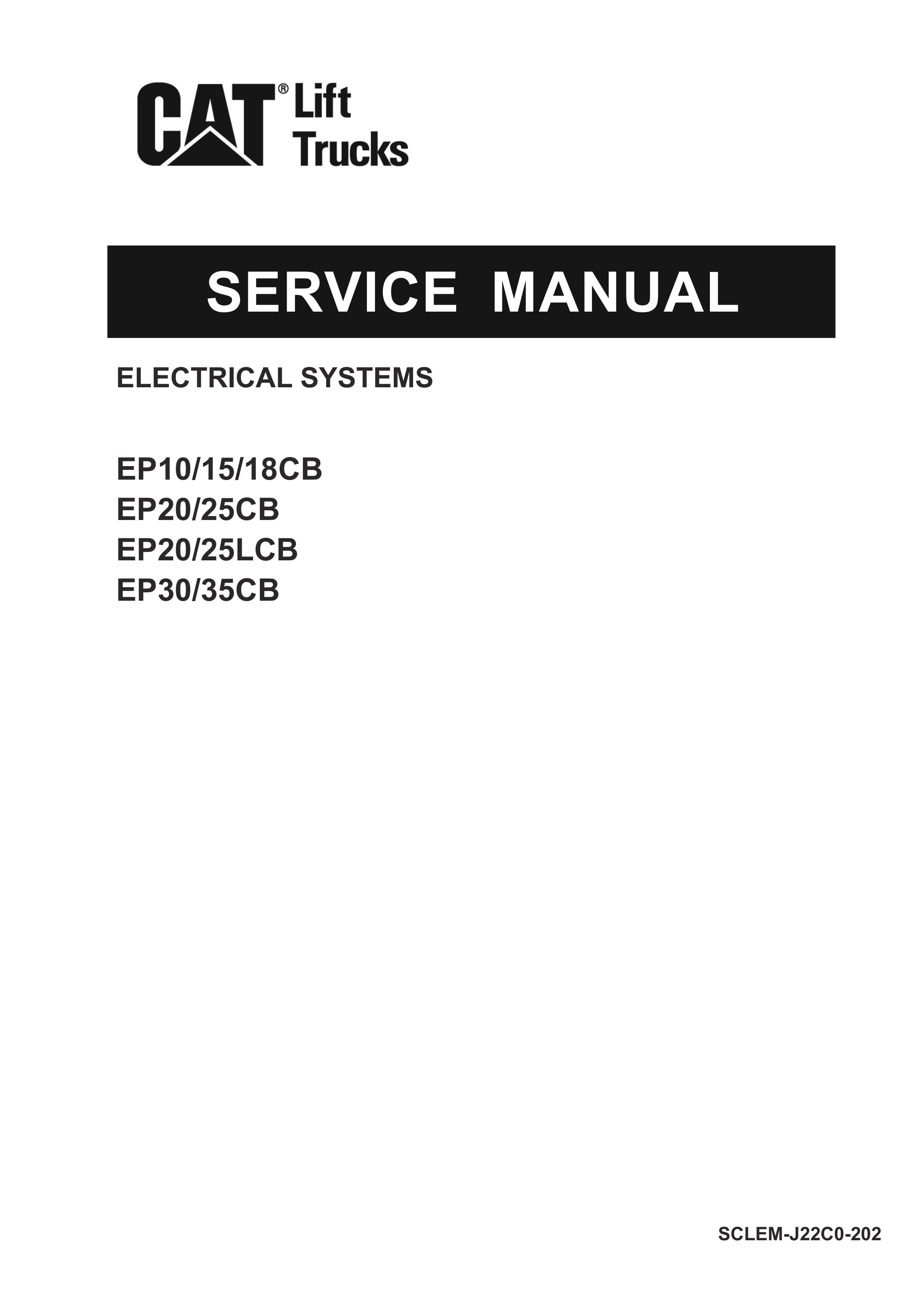
Caterpillar EB10CB-35CB, EB20-25LCB Electrical Systems Service Manual SCLEM-J22C0-202
$50.00
- Type Of Manual: Service Manual
- Manual ID: SCLEM-J22C0-202
- Number of Pages: 227
- Size: 9.3MB
- Format: PDF
Product details
-
Model List:
- EB10CB, EB15CB, EB18CB, EB20CB, EB25CB, EB20LCB, EB25LCB, EB30CB, EB35CB
- 1. SCLEM-J22C0-202-00_Foreword_78509
- 1.1. Front cover_CAT
- 1.2. FOREWORD
- 2. SCLEM-J22C0-202-01_BC_78510
- 2.1. BATTERY
- 2.2. Specification
- 2.3. Inspection
- 2.4. Wiring Harness Arrangement for the Optional Battery Electrolyte Level Warning
- 2.5. Cleaning the Battery
- 2.6. Storing the Battery
- 2.7. CHARGER (STATIONARY BUILT IN TYPE OPTIONAL)
- 2.8. Specification
- 2.9. Layout
- 2.10. Assembly Drawing
- 2.11. Inspection
- 2.12. Adjusting the Charger
- 2.13. Measuring the No-Load Charging Voltage
- 2.14. AUTOMATIC BATTERY FLUID SUPPLY (OPTIONAL)
- 2.15. Layout
- 2.16. Function
- 2.17. Inspection
- 3. SCLEM-J22C0-202-02_CM_78511
- 3.1. SERVICE INFORMATION
- 3.2. CONTROLLER ASSY
- 3.3. Layout
- 3.4. Controller Harness
- 3.5. Controller Harness Layout
- 3.6. TRV HYD CONTROLLERS
- 3.7. Construction
- 3.8. Disassembly / Reassembly
- 3.9. Inspection
- 3.10. Terminal Layout
- 3.11. PS CONTROLLER
- 3.12. Construction
- 3.13. Inspection
- 3.14. Terminal Layout
- 3.15. OPT CONTROLLER (FOR PROPORTIONAL VALVE)
- 3.16. External Appearance
- 3.17. Terminal Layout
- 3.18. CONTROLLER-RELATED COMPONENTS
- 3.19. Fuse
- 3.20. Contactor
- 3.21. Cooling Fan (for 2.0, 2.5 ton)
- 3.22. TRV MOTOR
- 3.23. Construction
- 3.24. Exploded Views
- 3.25. Replacing the Bearing Sensor
- 3.26. HYD MOTOR
- 3.27. Construction
- 3.28. Exploded Views
- 3.29. PS MOTOR
- 3.30. Construction
- 3.31. Replacing the Bearing Sensor
- 4. SCLEM-J22C0-202-03_DS_78512
- 4.1. CONTROL FUNCTION (EXCERPTS FROM OPERATION MAINTENANCE MANUAL)
- 4.2. Safety Function
- 4.3. Support Function
- 4.4. METER PANEL SCREEN (EXCERPTS FROM OPERATION MAINTENANCE MANUAL)
- 4.5. Meter Panel Screen
- 4.6. Meter Panel Screen Basic Flow
- 4.7. Meter Panel Switch
- 4.8. Mode Display
- 4.9. Normal Screen
- 4.10. Operation Results
- 4.11. User Setting
- 4.12. Simple PIN Code (Password) Entry Optional
- 4.13. Manager PIN Code (Password) Entry
- 4.14. Manager Settings
- 4.15. Maintenance Timer
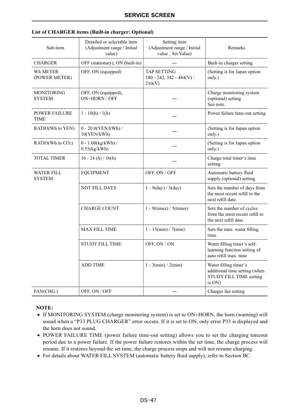
- 4.16. CHARGE Screen (Built-in Charger Optional)
- 4.17. SERVICE SCREEN
- 4.18. SERVICE Screen Flowchart
- 4.19. SETTING
- 4.20. MONITOR
- 4.21. ERROR HISTORY
- 4.22. CALIBRATION (Sensor Calibration and Initial Settings)
- 4.23. INITIALIZE (Reset the Settings)
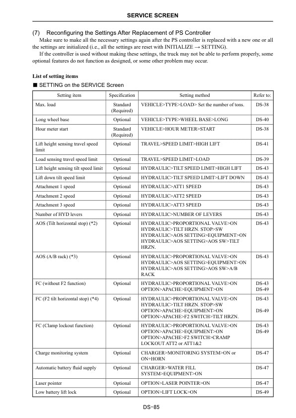
- 4.24. Reconfiguring the Settings After Replacement of PS Controller
- 4.25. CHARGE TEST Screen (Built-in Charger Optional)
- 5. SMLEM-J22C0-202-06_WD_78515
- 5.1. SERVICE INFORMATION
- 5.2. WIRING DIAGRAM
- 5.3. CIRCUIT DIAGRAM
- 5.4. Power Steering
- 5.5. Built-in Charger
- 5.6. Display
- 5.7. Travel Travel/Traction Motor, Accelerator, Directional Switch
- 5.8. Travel Service Brake, Main Contactor, Travel Related CSM
- 5.9. Travel Brake Oil Level, Seat Seatbelt
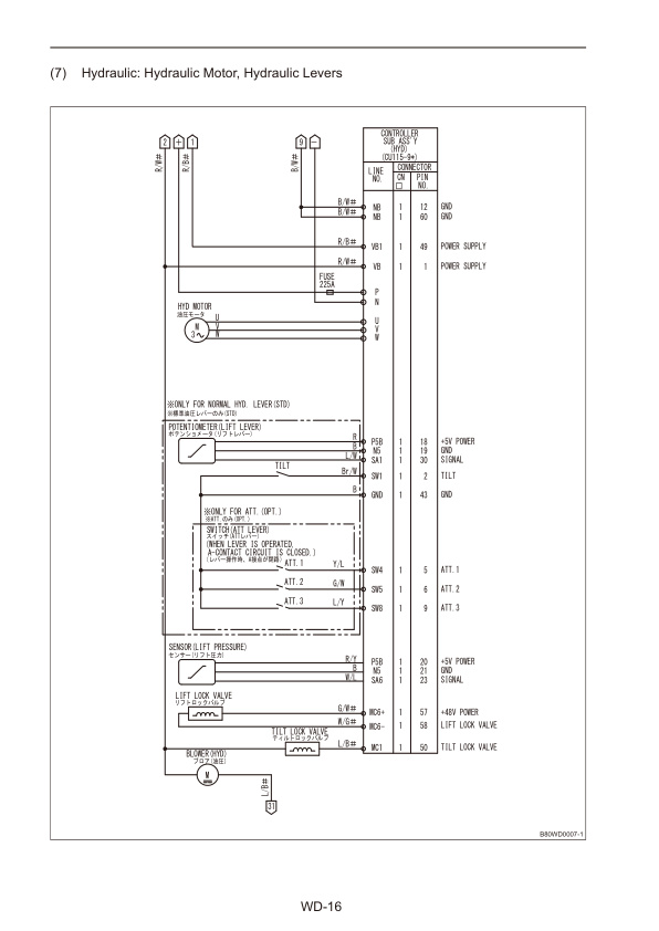
- 5.10. Hydraulic Hydraulic Motor, Hydraulic Levers
- 5.11. Hydraulic Hydraulic Related Options
- 5.12. Hydraulic Optional Fingertip Lever (Electromagnetic Proportional Control Valve)
- 5.13. Lightings I
- 5.14. Lightings II Laser Pointer Optional Lightings
- 5.15. Lightings III Optional Lightings Continued
- 5.16. Horn
- 5.17. Buzzer Chime
- 5.18. Battery Related Options
- 5.19. Optional Front Window with Wiper Washer
- 5.20. Optional Load Sensor
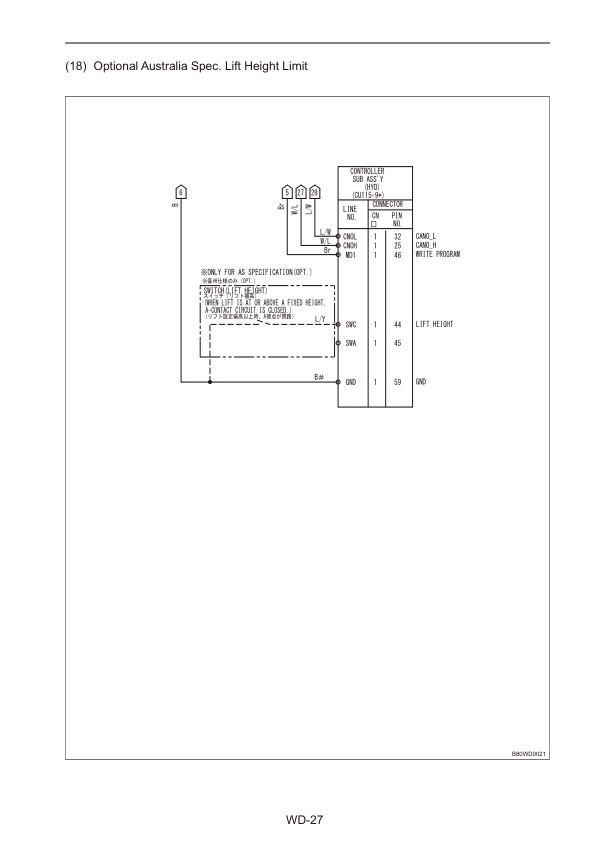
- 5.21. Optional Australia Spec. Lift Height Limit
- 5.22. HARNESS
- 5.23. Wiring Harness (Standard)
- 5.24. Wiring Harness (Optional)
- 5.25. Wiring Harness (Optional Electromagnetic Proportional Control Valve for AOS/FC)
- 5.26. Body Harness (Standard)
- 5.27. Body Harness (Optional)
- 5.28. Body Harness (Optional Electromagnetic Proportional Control Valve for AOS/FC)
- 5.29. Optional Harness
- 5.30. BUILT-IN CHARGER (OPTIONAL)
- 5.31. Charging Circuit Diagram
- 5.32. Charger Harness (for 5.2/6.4kVA transformers)
- 5.33. Charger Harness (for 7.0/11.0kVA transformers)
- 5.34. OPTIONAL
- 5.35. Automatic Battery Fluid Supply
- 5.36. Laser Pointer
- 5.37. Front Operation Lightings
- 5.38. Rear Lightings
- 5.39. Rear LED Line
- 5.40. Spot Light
- 5.41. Buzzer, Chime
- 5.42. Front Window
- 5.43. Charge Monitoring System (CMS, Built-in Charger)
- 5.44. Lift Limit
- 5.45. Lift Limit with Switch
- 5.46. DC/DC Converter
- 5.47. Clamp Lockout
- 5.48. Back cover_MIT
Related products
-
Caterpillar 2EC15-30 Chassis and Mast Service Manual 99759-80100
$50.00 Add to cart -
Caterpillar 4G15, 4G63, 4G64, 6G72 Engine Service Manual 99719-34130
$50.00 Add to cart -
Caterpillar 4G15 Gasoline Engine Service Manual 99719-36110
$50.00 Add to cart -
Caterpillar 1204E Diesel Engine Troubleshooting Service Manual 99799-64104
$50.00 Add to cart -

Caterpillar 1204F Diesel Engine Troubleshooting Service Manual 99799-67104
$50.00 Add to cart


