
(C)(H)(X)%20Service%20Manual%20622076&url=https://ownersmanualpdf.net/docs/caterpillar-nr14-25n2schx-service-manual-622076/&media=https://ownersmanualpdf.net/wp-content/uploads/2025/10/caterpillar-nr14-25n2schx-service-manual-622076-1.jpg)
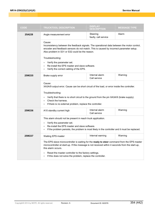
Caterpillar NR14-25N2(S)(C)(H)(X) Service Manual 622076
$50.00
- Type Of Manual: Service Manual
- Manual ID: 622076
- Number of Pages: 442
- Size: 57.2MB
- Format: PDF
Product details
-
Model List:
- NR14-25N2(S)(C)(H)(X)
- 1. Contents
- 2. Foreword
- 3. How to read this manual
- 3.1. Safety-related signs
- 3.2. Symbols and abbreviations
- 3.2.1. Safety symbols
- 3.2.2. Other symbols and abbreviations
- 3.3. Units
- 4. Safety instructions
- 4.1. Service area safety
- 4.2. Personal safety
- 4.3. Work safety
- 5. General information
- 5.1. Truck model covered by this manual
- 5.2. Identification plates on the truck
- 5.3. Overview of the truck
- 5.3.1. Operating devices
- 5.3.2. Control panel
- 5.3.3. Steering wheel
- 5.3.4. Arm rest
- 5.3.5. Display panel
- 5.3.6. Truck operation modes
- 5.3.7. Truck display
- 5.3.8. Pedals
- 5.3.9. Operators seat
- 5.3.10. Operating position
- 5.3.11. Driving direction
- 5.3.12. Motor, hydraulic system and electrical system
- 5.3.13. Sensors
- 5.3.14. Reach carriage
- 5.3.15. Mast unit
- 5.3.16. Load support
- 6. Mechanical maintenance
- 6.1. Lifting points
- 6.1.1. Jack points
- 6.1.2. Hoist points
- 6.2. Transportation
- 6.3. Assembly and commissioning
- 6.3.1. Install the mast unit
- 6.4. Order spare parts
- 6.5. Truck covers
- 6.5.1. Remove the machinery cover
- 6.5.2. Remove the front bumper
- 6.5.3. Remove the floor plate
- 6.5.4. Open the machinery top cover
- 6.5.5. Open the instrument panel
- 6.5.6. Remove the instrument panel cover
- 6.5.7. Remove the control panel
- 6.5.8. Remove the cup holder
- 6.5.9. Remove the reach carriage cover
- 6.6. Steering wheel
- 6.6.1. Remove the steering wheel
- 6.7. Transmission gear
- 6.7.1. Remove the transmission gear
- 6.8. Slewing bearing
- 6.8.1. Lubricate the slewing bearing
- 6.9. Traction wheel
- 6.9.1. Disassemble the traction wheel
- 6.9.2. Assemble the traction wheel
- 6.10. Corner supports
- 6.10.1. Replace the corner supports
- 6.11. Load wheels
- 6.11.1. Remove the load wheels
- 6.12. Battery roller frame
- 6.12.1. Remove the battery roller frame
- 6.13. Reach carriage
- 6.13.1. Lubricate the rollers of the reach carriage
- 6.13.2. Adjust the guidance rollers of the reach carriage
- 6.13.3. Sensors of the reach carriage
- 6.13.4. Remove the reach carriage
- 6.13.5. Remove the reach cylinder
- 6.13.6. Replace the reach carriage hoses
- 6.14. Mast unit
- 6.14.1. Detailed construction
- 6.14.2. Mast unit maintenance
- 6.14.3. Lubricant recommendations
- 6.14.4. Remove the lifting carriage
- 6.14.5. Remove the mast unit
- 6.14.6. Disassemble the mast unit
- 6.14.7. Fork inspection
- 6.14.8. Mast chains
- 6.14.9. Guidance rollers
- 6.14.10. Main rollers
- 6.14.11. Free lift cylinder
- 6.14.12. Side cylinders
- 6.14.13. Tilt cylinders
- 6.14.14. Sideshift cylinder
- 6.15. Load support
- 6.15.1. Remove the load support
- 6.16. Arm rest
- 6.16.1. Remove the arm rest
- 6.16.2. Open the arm rest
- 6.16.3. Remove the arm rest levers
- 6.16.4. Remove the arm rest buttons
- 6.17. Operators seat
- 6.17.1. Replace the seat switch
- 7. Electrical operation
- 7.1. How to use the schematic diagram
- 7.2. Power source
- 7.3. Safety circuit (emergency stop button)
- 7.4. Key switch
- 7.5. Traction
- 8. Battery maintenance
- 8.1. Safety regulations concerning the handling of lead-acid batteries
- 8.2. Battery maintenance
- 8.2.1. Daily maintenance
- 8.2.2. Weekly maintenance
- 8.2.3. Monthly maintenance
- 8.2.4. Annual maintenance
- 8.3. Recharge the battery
- 8.4. Measure the specific gravity of the battery
- 8.5. Replace the battery
- 8.5.1. Guide the battery connector cables
- 8.6. Quick battery replacement
- 9. Electric system maintenance
- 9.1. Display panel
- 9.1.1. Emergency stop button
- 9.1.2. Key switch
- 9.2. Pedals
- 9.2.1. Operator presence pedal
- 9.2.2. Acceleration pedal
- 9.2.3. Brake pedal
- 9.3. Instrument panel
- 9.3.1. Discharge the controllers
- 9.3.2. Vehicle controller
- 9.3.3. Vehicle controller connectors
- 9.3.4. Traction controller
- 9.3.5. Traction controller connectors
- 9.3.6. Pump controller
- 9.3.7. Pump controller connectors
- 9.3.8. Steering controller
- 9.3.9. Steering controller connectors
- 9.3.10. Fuses
- 9.3.11. Remove the gas spring of the instrument panel
- 9.4. Motor compartment
- 9.4.1. Traction motor
- 9.4.2. Steering motor
- 9.4.3. Magnetic brake
- 9.4.4. Release the magnetic brake manually
- 9.5. Pump motor
- 9.5.1. Pump motor (Standard model)
- 9.5.2. Pump motor (High performance model)
- 9.5.3. Replace the HALL sensor
- 9.6. Sensors
- 9.6.1. Steering wheel sensor
- 9.6.2. Steering reference sensor
- 9.6.3. Reach end stop, retract limit, retract end stop and reach limit switch
- 9.6.4. Battery lock sensor
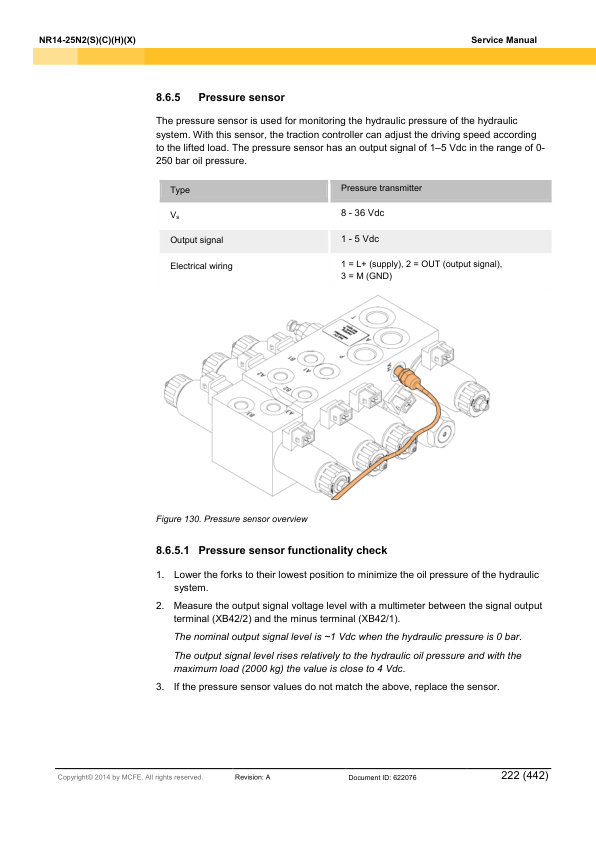
- 9.6.5. Pressure sensor
- 9.6.6. Height reference sensor
- 10. Electric system adjustments and measurements
- 10.1. Calibrate the arm rest levers
- 10.2. Insulation resistance test
- 10.2.1. Test voltage
- 10.2.2. Checking the insulation tester
- 10.2.3. Measure the insulation resistance
- 11. Hydraulic operation
- 11.1. Hydraulic symbols
- 11.2. Hydraulic oil recommendations
- 11.3. Maintenance points of the hydraulic system
- 11.3.1. Replace the hydraulic oil return filter (sieve)
- 11.3.2. Clean the hydraulic oil suction filter
- 11.4. Hydraulic system
- 11.4.1. Disassemble the hydraulic system
- 11.5. Hydraulic valve unit
- 11.5.1. Valve M1
- 11.5.2. Valve M3, M4, M7 and M8
- 11.5.3. Valve M2, M5, M6, M9 and M10
- 11.5.4. Emergency lowering valve
- 11.5.5. Set the lifting pressure
- 11.5.6. Disassemble the valves
- 12. TruckTool Diagnostics
- 13. Parameter descriptions
- 13.1. VCM
- 13.2. Traction controller
- 13.3. Pump controller
- 13.4. EPS controller
- 14. Alarm codes
- 14.1. VCM
- 14.1.1. VCM master
- 14.1.2. VCM slave
- 14.2. Traction controller
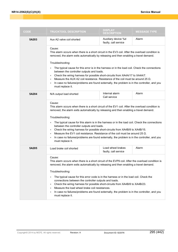
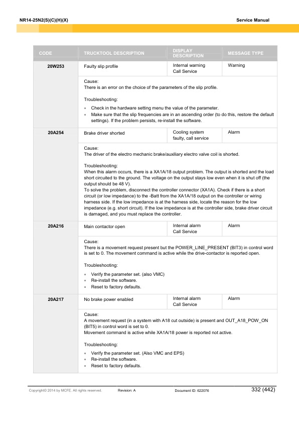
- 14.3. Pump controller
- 14.4. EPS
- 14.4.1. EPS master
- 14.4.2. EPS slave
- 15. Service data
- 15.1. Special tightening torques
- 15.2. Tightening torque for standard bolts and nuts
- 15.3. Maintenance check list
- 15.4. Lubrication
- 15.4.1. Hydraulic oil
- 15.4.2. Transmission oil
- 15.5. Special tools
- 16. Options
- 16.1. Special color labels
- 16.2. Customer design labels
- 16.3. Display languages
- 16.4. Accessory rack
- 16.4.1. Install the accessory rack
- 16.4.2. Install the list bracket
- 16.4.3. Install the computer rack
- 16.4.4. Install the rear view mirror
- 16.5. Accessory rack under the truck floor
- 16.5.1. Install the accessory rack under the floor
- 16.6. Reading lamp
- 16.6.1. Install the reading lamp
- 16.7. Audio system
- 16.7.1. Install the audio system
- 16.8. Warning light
- 16.8.1. Install the warning light
- 16.9. Working lights
- 16.9.1. Install the working lights
- 16.10. Operator compartment fan
- 16.10.1. Install the operator compartment fan
- 16.11. Drive alarm (programmable)
- 16.11.1. Install the drive alarm
- 16.12. Steel safety net for overhead guard
- 16.12.1. Install the steel safety net to the overhead guard
- 16.13. Plexiglass safety cover for the overhead guard
- 16.13.1. Install the plexiglass safety cover to the overhead guard
- 16.14. Left shoulder protection plate
- 16.14.1. Install the left shoulder protection plate
- 16.15. Fire extinguisher
- 16.15.1. Install the fire extinguisher
- 16.16. Cold storage modification
- 16.17. Hot storage modification
- 16.18. Current output
- 16.18.1. Install the DC-DC converter
- 16.19. Quick battery changing device for 2 batteries
- 16.19.1. Remove an empty battery with the battery changing device for 2 batteries
- 16.19.2. Install a recharged battery with the battery changing device for 2 batteries
- 16.20. Battery connector cables
- 16.20.1. Replace the battery connector
- 16.21. Charger connector
- 16.21.1. Replace the charger connector
- 16.22. Extra valve with hosing to fork carriage
- 16.23. Fork positioner with sideshift
- 16.24. Fork carriage strengthening part
- 16.25. Fork camera with 7 LCD color display
- 16.26. Telescopic forks
- 16.27. Sideshift and tilt centering
- 16.27.1. Sideshift centering direction, sideshift centering midpoint and tilt centering sensor
- 16.28. Load weight indicator
- 16.29. Electric load wheel brakes
- 16.30. Lowering cut-off
- 16.31. Operators seat options and accessories
- 16.31.1. Arm rest
- 16.31.2. Backrest extension for MSG65/MSG75
- 16.31.3. Seat belt for MSG20 seat
- 16.32. PIN code access to the Start switch
- 16.33. Lifting height pre-selection
- 16.33.1. How to unstack with the lifting height pre-selection
- 16.33.2. How to stack with the lifting height pre-selection
- 17. Technical specification
- 17.1. NR14N2S, NR14N2HS, NR16N2S, NR16N2HS and NR16N2
- 17.2. NR16N2H, NR16N2C, NR16N2HC, NR20N2H, NR20N2X and NR25N2X
- 17.3. Mast heights
- 18. Index
- 19. APPENDIX A Stickers
Related products
-
Caterpillar 1204E Diesel Engine Specifications Service Manual 99799-64101
$50.00 Add to cart -

Caterpillar 1204E Diesel Engine Systems Operation Testing and Adjusting Service Manual 99799-64103
$50.00 Add to cart -
Caterpillar 1204E Diesel Engine Disassembly and Assembly Service Manual 99799-64102
$50.00 Add to cart -
Caterpillar 1204F Diesel Engine Specifications Service Manual 99799-67101
$50.00 Add to cart -
Caterpillar 4G15 Gasoline Engine Service Manual 99719-36110
$50.00 Add to cart


