

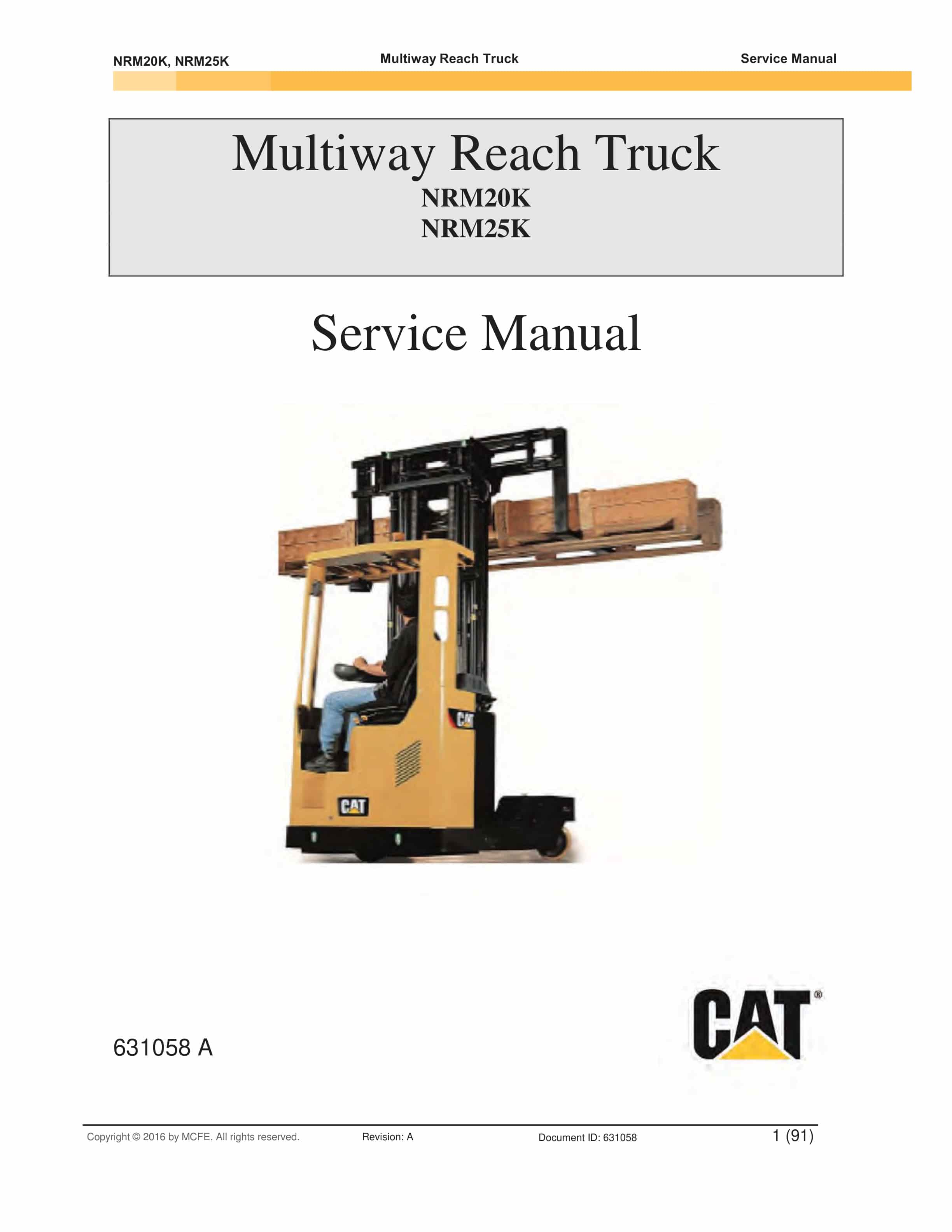

Caterpillar NRM20K, NRM25K Multiway Reach Truck Service Manual 631058
$50.00
- Type Of Manual: Service Manual
- Manual ID: 631058
- Number of Pages: 325
- Size: 6.1MB
- Format: PDF
Product details
-
Model List:
- NRM20K, NRM25K Multiway Reach Truck
- 1.
- 2.
- 3.
- 4.
- 5.
- 6.
- 7.
- 7.1. Table of Contents
- 7.2. Scope of this Manual
- 7.3. Related Documents
- 7.4. Intended Use of the AC SuperDrive
- 7.5. Product Identification
- 7.6. Technical Support
- 7.7. Product Warranty
- 7.8. Introduction
- 7.9. Tools and Equipment Required
- 7.10. Orientation
- 7.11. Clearances for Access and Air Circulation
- 7.12. Procedure
- 7.13. Introduction
- 7.14. Tools and Equipment Required
- 7.15. Motor and Battery Connections
- 7.15.1. General
- 7.15.2. Making Connections to Terminal Posts
- 7.15.3. Inrush Current Limiting Resistance
- 7.15.4. Main Contactor
- 7.15.5. Key Start Input
- 7.16. Control and I/O Connections
- 7.16.1. General
- 7.16.2. ID0 and ID1 Inputs
- 7.16.3. Encoder Signals
- 7.16.4. Temperature Sensor
- 7.16.5. CAN Bus Signals
- 7.16.6. Crimping Contacts onto Signal Conductors
- 7.16.7. Installing Crimped Contacts in Connector Housing
- 7.17. General
- 7.18. Checks Prior to Initial Powerup
- 7.19. Verifying AC SuperDrive Readiness for Operation
- 7.20. Configuring the AC SuperDrive for the Application
- 7.21. Final Operational Checks in Vehicle
- 7.22. Introduction
- 7.23. Periodic Preventive Maintenance
- 7.24. AC SuperDrive Replacement Procedure
- 7.24.1. Drive Removal
- 7.24.2. Drive Installation
- 7.25. Scope of the Troubleshooting Guide
- 7.26. Using the Troubleshooting Guide
- 7.26.1. Organization of Troubleshooting Guide
- 7.26.2. About Errors and Warnings
- 7.26.3. Error Logging
- 7.26.4. Using the Troubleshooting Charts
- 7.27. Information for OEMs Preparing User Documentation
- 7.28. Symptom Main Contactor doesnt close after switching on Key Switch
- 7.29. Symptom Fuse to Power Stage is blown
- 7.30. Symptom AC SuperDrive Status Indicator is blinking or off
- 7.31. Symptom Motor runs only at low speed and with a ticking sound
- 7.32. Error Code 1 Pulse Sensor Error
- 7.33. Error Code 2 Motor Temperature High
- 7.34. Warning Code 16 Power limited due to Motor Overtemp.
- 7.35. Error Code 4 Heatsink Temperature high
- 7.36. Warning Code 1 Power Limited due to Heatsink Overtemp.
- 7.37. Error Code 8 Overcurrent
- 7.38. Error Code 16 DC Bus High – hardware detected
- 7.39. Error Code 32 DC Bus High – software detected
- 7.40. Error Code 64 DC Bus Low
- 7.41. Error Code 128 No Charging DC Bus
- 7.42. Error Code 256 CAN – too many Errors
- 7.43. Error Code 512 CAN Watchdog Time-out
- 7.44. Error Code 1024 Missing Okay to Start from Truck Controller
- 7.45. Error Code 2048 Contradictory Commands from Truck Controller
- 7.46. Error Code 4096 Potentiometer Values Out of Range
- 7.47. Warning Code 2 Heatsink Temperature Sensor Open Circuit
- 7.48. Warning Code 4 Heatsink Temperature Sensor Short Circuit
- 7.49. Warning Code 8 Power limited – temp < -20 deg. C
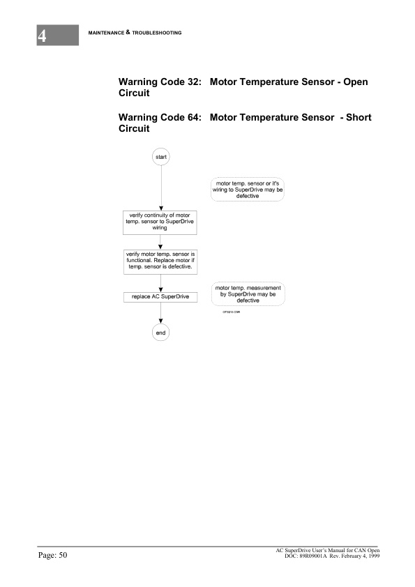
- 7.50. Warning Code 32 Motor Temperature Sensor – Open Circuit
- 7.51. Warning Code 64 Motor Temperature Sensor – Short Circuit
- 7.52. Warning Code 128 Speed from Truck Controller Out of Range
- 7.53. Warning Code 256 Current Calibration Error
- 7.54. Warning Code 512 Reverted to Default Parameters
- 7.55. _UM.pdf
- 7.55.1. Scope of this Manual
- 7.55.2. Related Documents
- 7.55.3. Intended Use of the AC SuperDrive
- 7.55.4. Product Identification
- 7.55.5. Technical Support
- 7.55.6. Product Warranty
- 7.55.7. Introduction
- 7.55.8. Tools and Equipment Required
- 7.55.9. Orientation
- 7.55.10. Clearances for Access and Air Circulation
- 7.55.11. Procedure
- 7.55.12. Introduction
- 7.55.13. Tools and Equipment Required
- 7.55.14. Motor and Battery Connections
- 7.55.14.1. General
- 7.55.14.2. Making Connections to Terminal Posts
- 7.55.14.3. Inrush Current Limiting Resistance
- 7.55.14.4. Main Contactor
- 7.55.14.5. Key Start Input
- 7.55.15. Control and I/O Connections
- 7.55.15.1. General
- 7.55.15.2. ID0 and ID1 Inputs
- 7.55.15.3. Encoder Signals
- 7.55.15.4. Temperature Sensor
- 7.55.15.5. CAN Bus Signals
- 7.55.15.6. Crimping Contacts onto Signal Conductors
- 7.55.15.7. Installing Crimped Contacts in Connector Housing
- 7.55.16. General
- 7.55.17. Checks Prior to Initial Powerup
- 7.55.18. Verifying AC SuperDrive Readiness for Operation
- 7.55.19. Configuring the AC SuperDrive for the Application
- 7.55.20. Final Operational Checks in Vehicle
- 7.55.21. Introduction
- 7.55.22. Periodic Preventive Maintenance
- 7.55.23. AC SuperDrive Replacement Procedure
- 7.55.23.1. Drive Removal
- 7.55.23.2. Drive Installation
- 7.55.24. Obtaining Factory Repair
- 7.55.25. Scope of the Troubleshooting Guide
- 7.55.26. Using the Troubleshooting Guide
- 7.55.26.1. Organization of Troubleshooting Guide
- 7.55.26.2. About Errors and Warnings
- 7.55.26.3. Error Logging
- 7.55.26.4. Using the Troubleshooting Charts
- 7.55.27. Information for OEMs Preparing User Documentation
- 7.55.28. Symptom Main Contactor doesnt close after switching on Key Switch
- 7.55.29. Symptom Fuse to Power Stage is blown
- 7.55.30. Symptom AC SuperDrive Status Indicator is blinking or off
- 7.55.31. Symptom Motor runs only at low speed and with a ticking sound
- 7.55.32. Error Code 1 Pulse Sensor Error
- 7.55.33. Error Code 2 Motor Temperature High
- 7.55.34. Warning Code 16 Power limited due to Motor Overtemp.
- 7.55.35. Error Code 4 Heatsink Temperature high
- 7.55.36. Warning Code 1 Power Limited due to Heatsink Overtemp.
- 7.55.37. Error Code 8 Overcurrent
- 7.55.38. Error Code 16 DC Bus High – hardware detected
- 7.55.39. Error Code 32 DC Bus High – software detected
- 7.55.40. Error Code 64 DC Bus Low
- 7.55.41. Error Code 128 No Charging DC Bus
- 7.55.42. Error Code 256 CAN – too many Errors
- 7.55.43. Error Code 512 CAN Watchdog Time-out
- 7.55.44. Error Code 1024 Missing Okay to Start from Truck Controller
- 7.55.45. Error Code 2048 Contradictory Commands from Truck Controller
- 7.55.46. Error Code 4096 Potentiometer Values Out of Range
- 7.55.47. Warning Code 2 Heatsink Temperature Sensor Open Circuit
- 7.55.48. Warning Code 4 Heatsink Temperature Sensor Short Circuit
- 7.55.49. Warning Code 8 Power limited – temp < -20 deg. C
- 7.55.50. Warning Code 32 Motor Temperature Sensor – Open Circuit
- 7.55.51. Warning Code 64 Motor Temperature Sensor – Short Circuit
- 7.55.52. Warning Code 128 Speed from Truck Controller Out of Range
- 7.55.53. Warning Code 256 Current Calibration Error
- 7.55.54. Warning Code 512 Reverted to Default Parameters
- 7.55.54.1. Table of Contents
- 8.
- 8.1. Table of Contents
- 8.2. Introduction
- 8.2.1. About APS Documentation
- 8.2.1.1. Scope of this Manual
- 8.2.1.2. Intended Use
- 8.2.1.3. Related Documents
- 8.2.2. About the Advanced Power Steering Unit
- 8.2.2.1. Intended Use
- 8.2.2.2. Safety Instructions
- 8.2.2.3. Technical Support
- 8.2.2.4. Product Warranty
- 8.3. APS Installation
- 8.3.1. Installing APS in Vehicle
- 8.3.1.1. Introduction
- 8.3.1.2. Installing the Actuator
- 8.3.1.3. Installing a Separately mounted Controller
- 8.3.2. Installing Steering Feedback Sensors
- 8.3.2.1. Introduction
- 8.3.2.2. Potentiometer
- 8.3.2.3. Home Cam with Center Position Sensor
- 8.3.2.4. Home Cam with Combination Center/End Limit Sensor
- 8.3.3. Installing Steering Input Sensors
- 8.3.3.1. Introduction
- 8.3.3.2. Stepper Motor
- 8.3.3.3. Joystick or Potentiometer
- 8.3.3.4. Encoder
- 8.3.4. Wiring the APS
- 8.3.4.1. Introduction
- 8.3.4.2. Tools and Equipment Required
- 8.3.4.3. Wiring the APS Mating Connector
- 8.3.4.4. Battery Power Connections
- 8.3.4.5. Sensor, Safety and Communications Wiring
- 8.3.4.6. Actuator to Separately Mounted Controller Cabling
- 8.4. Startup and Commissioning
- 8.4.1. Initial Startup
- 8.4.1.1. General Information
- 8.4.1.2. Checks Prior to Initial Powerup
- 8.4.1.3. Verifying APS Unit Readiness for Operation
- 8.4.1.4. Configuring the APS for the Application
- 8.4.1.5. Operational Checks in Vehicle
- 8.5. Maintenance
- 8.5.1. Maintenance Procedures
- 8.5.1.1. Introduction
- 8.5.1.2. Periodic Inspection and Preventive Maintenance
- 8.5.1.3. Steering Feedback Calibration
- 8.5.2. APS Replacement Procedures
- 8.5.2.1. Safety Information
- 8.5.2.2. APS with Integrated Controller
- 8.5.2.3. APS with Separately Mounted Controller
- 8.6. Troubleshooting
- 8.6.1. Introduction
- 8.6.1.1. Terms and Definitions
- 8.6.1.2. Troubleshooting Data Available from APS
- 8.6.2. The Troubleshooting Guide
- 8.6.2.1. General
- 8.6.2.2. Using the Troubleshooting Guide
- 8.6.2.3. General Troubleshooting Procedure
- 8.6.2.4. Information for OEMs Preparing User Documentation
- 8.6.2.5. LED status Indicator is Off
- 8.6.2.6. High Current Error
- 8.6.2.7. Voltage Error
- 8.6.2.8. High Temp Error
- 8.6.2.9. Watchdog Reset
- 8.6.2.10. Hardware Power Protection Trip
- 8.6.2.11. Safety Out Error
- 8.6.2.12. Steer Sensor Error
- 8.6.2.13. Switch Error
- 8.6.2.14. Feedback Sensor Error
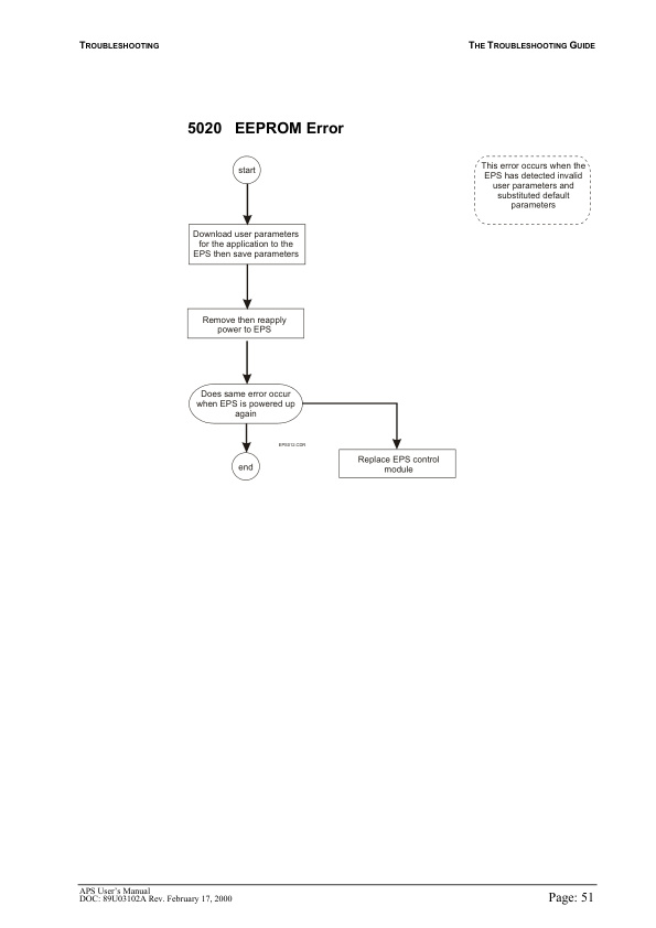
- 8.6.2.15. EEPROM Error
- 8.6.2.16. Motor Error
- 8.6.2.17. Position Error
- 8.6.2.18. Communications Timeout Error
- 9.
- 9.1. Table of Contents
- 9.2. Introduction
- 9.2.1. About CANION Documentation
- 9.2.1.1. Scope of this Manual
- 9.3. Technical Description
- 9.3.1. Principles of Operation
- 9.3.1.1. Introduction
- 9.3.1.2. Introduction
- 9.3.1.3. CANION Software
- 9.4. Applications
- 9.4.1. Order Picker
- 9.4.2. Order Picker
- 9.4.2.1. Reach Truck
- 9.5. Interfacing to CANION
- 9.5.1. Interfacing Input Devices
- 9.5.1.1. General
- 9.5.2. Interfacing Input Devices
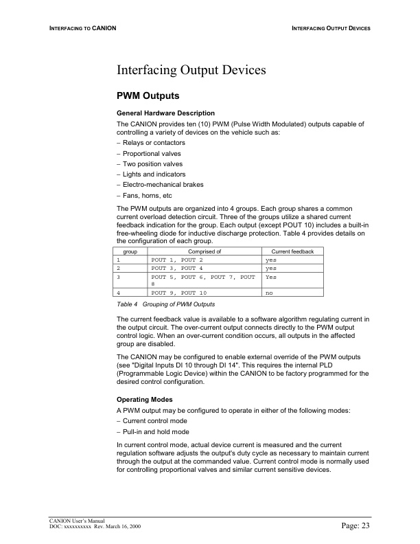
- 9.5.2.1. PWM Outputs
- 9.5.3. Interfacing Output Devices
- 9.5.3.1. Interfacing CANION in a Truck Can Network
- 9.5.4. Can Bus Communications
- 9.5.4.1. General Configuration
- 9.6. Installation and Wiring
- 9.6.1. CANION Installation
- 9.6.1.1. Mounting CANION in a Vehicle
- 9.6.2. CANION Installation
- 9.6.2.1. Introduction
- 9.7. Specifications
- 9.7.1. Electrical Power Inputs Outputs
- 10.
- 11.
- 11.1. TS761104
- 11.1.1. AC-NRM 20K/25K
- 11.1.1.1. POWERSUPPLY 48V
- 11.1.1.2. POWERSUPPLY 12/24V
- 11.1.1.3. MAINCIRCUITS
- 11.1.1.4. DRIVECIRCUIT 1
- 11.1.1.5. DRIVECIRCUIT 2
- 11.1.1.6. STEERING CIRCUIT
- 11.1.1.7. STEERING CIRCUIT 2
- 11.1.1.8. STEERING CIRCUIT 3
- 11.1.1.9. HYDRAULIC CONTROL CIRCUIT 1
- 11.1.1.10. HYDRAULIC CONTROL CIRCUIT 2
- 11.1.1.11. CONTROL CIRCUIT 1
- 11.1.1.12. CONTROL CIRCUIT 2
- 11.1.1.13. SIGNAL- /LIGHTCIRCUIT
- 11.1.1.14. FANS, AUX.DEVICES
- 11.1.1.15. AUX.DEVICES
- 11.1.1.16. LAYOUT
- 11.1.1.17. LAYOUT
- 11.1.1.18. WIRE HARNESS W3 RL468152
- 12.
- 12.1. TS1050000
- 12.1.1. TEM AC SAUER DANFOSS
- 12.1.1.1. POWER SUPPLY 48V
- 12.1.1.2. MAIN CIRCUITS
- 12.1.1.3. DRIVE CIRCUIT
- 12.1.1.4. DRIVE CIRCUIT 2
- 12.1.1.5. STEERING CIRCUIT 1
- 12.1.1.6. HYDRAULIC CONTROL CIRCUIT
- 12.1.1.7. AUX DEVICES
- 12.1.1.8. STEERING CIRCUIT
- 12.1.1.9. CONTROL CIRCUIT
- 12.1.1.10. SIGNAL/LIGHT CIRCUITS
- 12.1.1.11. CSM FLASH LIGHTS WITH RUBBER BODY
- 12.1.1.12. 24V POWER SUPPLY/AUX DEVICES
- 12.1.1.13. MAIN WIRE HARNESS 479690
- 12.1.1.14. MAIN WIRE HARNESS 479690
- 12.1.1.15. PUSH WIRE HARNESS 480917
- 12.1.1.16. SUPPLY AND MOTOR CABLES 479691
- 12.1.1.17. INSTRUMENT PANEL WIRE HARNESS 479692
- 12.1.1.18. PIN CODE LOCK 480016
- 12.1.1.19. PEDALS 482458
- 13.
- 14.
Related products
-
Caterpillar 1204F Diesel Engine Specifications Service Manual 99799-67101
$50.00 Add to cart -
Caterpillar 1204E Diesel Engine Service Manual SCEEA-AT15E-200
$50.00 Add to cart -
Caterpillar 4G63, 4G64 Fuel System Supplement Service Manual 99729-85110
$50.00 Add to cart -

Caterpillar 2EC15 to 2EC30 MicroCommand II Control Service Manual SENB8609
$50.00 Add to cart -
Caterpillar 1.4 Liter (4G33) to 3.0 Liter (6G72) LP Gas Supplement Service Manual SENB8531
$50.00 Add to cart


%20to%203.0%20Liter%20(6G72)%20LP%20Gas%20Supplement%20Service%20Manual%20SENB8531&url=https://ownersmanualpdf.net/docs/caterpillar-1-4-liter-4g33-to-3-0-liter-6g72-lp-gas-supplement-service-manual-senb8531/&media=https://ownersmanualpdf.net/wp-content/uploads/2025/10/caterpillar-14-liter-4g33-to-30-liter-6g72-lp-gas-supplement-service-manual-senb8531-1.jpg)